Hi,
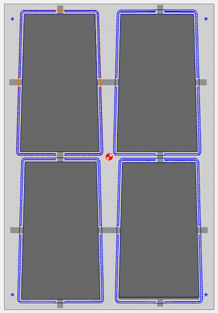
I have imported multiple STLs into the CC file attached (using CC build 843) and created outlines to cut the profiles as per this earlier post. Because these files require flip machining, I’ve added holes for alignment pins and now I would like to add tabs to hold the parts to the stock during both sides of the machining process. I added a “Tabs” layer to the design and created a model shape “flat” that is .34" high w/merge type “max” covering the tabs area. With 0.5" of stock that should leave ~ 0.18" of tab when both sides are cut (I’m only showing one side w/the attached file.
My question for anyone who might be able to figure it out - is why is the 3D rough toolpath not cutting all the way around the upper left and lower left quadrants of the design? It seems it might be a bug in the SW as there is nothing different about those quadrants of the design. Any workarounds or alternative methods for adding tabs that you would recommend?
Thanks!
Board_10F_Small_front_test.c2d (1.3 MB)