Adventure to a cheap optical tool setter

TL;DR: I rant about my experiments with tool width measurement. No world-changing outcome yet.

I’ve been trying to figure out how to conveniently mill holes and such on the Nomad while keeping tight tolerances (so that I can get the desired fits on holes). After this thread came up I speculated that my current issue might be the variance in endmill diameter, so I set out to measure it.

First, I did the obvious: milled something and measured to see how far off I was:

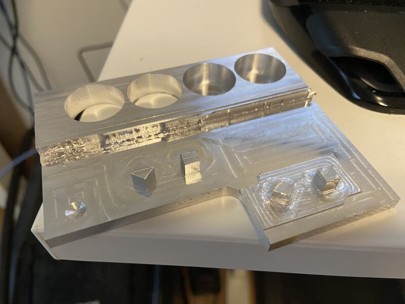
I milled 5mm pillars with a 3mm and 6mm endmill and then looked at the actual measurement. The toolpath was a pretty heavy 2D adaptive followed by a very light 2D contour.

For the 3mm endmill, the pillars ended up being 4.88mm, which, if my maths is right, means that the endmill took 0.12mm too much material off, which means the 3mm endmill is actually 3.12mm (or my collet results in more runout than I thought it would). Unfortunately I have no specs so can’t say what it should be.

For the 6mm endmill, the pillars were 5.06mm, which means the endmill is actually 5.94mm, which is theoretically just outside the h10 tolerance (+0/-0.058mm) the manufacturer claims but I’m willing to put that down to inaccuracy in the machine.

So it looks like there is some deviation and measuring tool diameter is worth it. Plowing through stock just to calibrate an endmill isn’t my idea of fun though so I looked at other options.

The way the big boys do this is a touch based probe like Renishaw OTS ($2300) or a laser-based probe like Renishaw NC4 ($4900) but that’s well outside my budget. Even the cheap Chinese clones cost $700.

I briefly thought about using my 3D probe as a tool setter, since that’s basically what a touch probe is but I wasn’t sure how to touch off it without damaging it. I talked to the manufacturer and he said it’s totally doable but you’d need to add a disc. My own thoughts were that such a disc would have to be of a very precisely-known diameter, be wear resistant and be precisely concentric with the probe. I thought that would be too much effort and it was unlikely to be affordable.

But having seen those laser-based probes, I thought how hard could it possibly be?

I did a bit of Googling and came across these things which, it turns out, cost barely more than $10 and have a repeatability of 10µm at worst. So I bought one and hooked it up (in a vise):

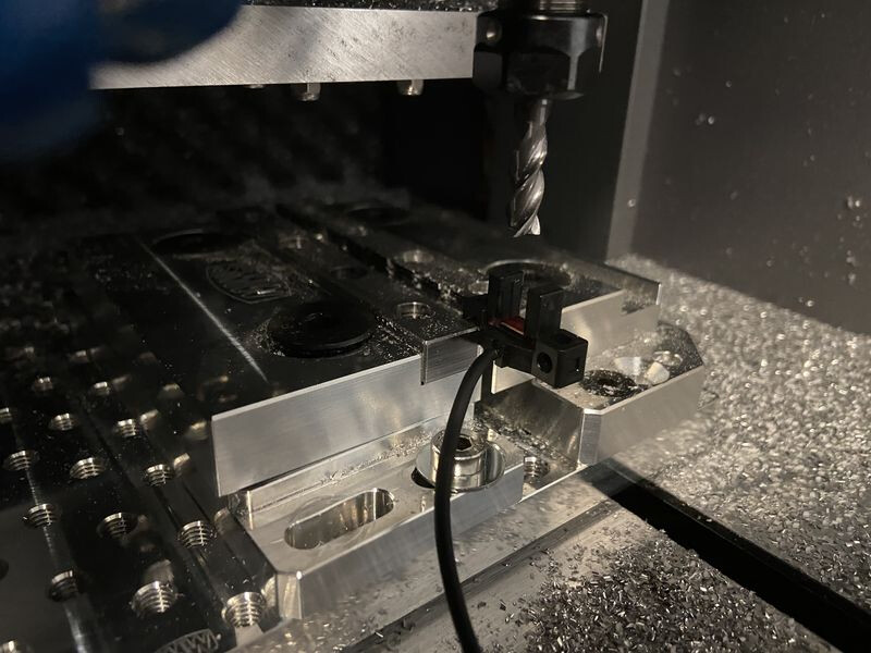
First I measured a 6mm h6-ground dowel pin, which I measured with a micrometer to have a diameter of ~5.99mm (maybe 5.995) and used that to calibrate, probing from right to left then left to right (manually, jogging). The difference in trigger points was 5.554mm, so I figured there was a 0.436mm-wide trigger zone.

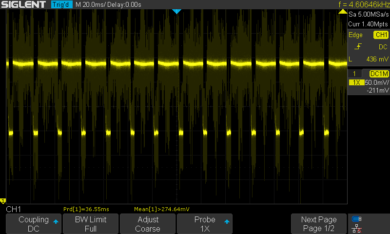
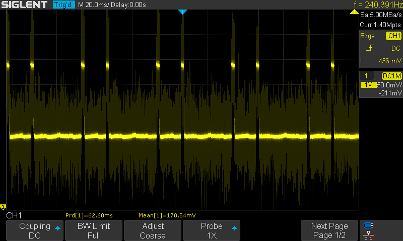
Then I tried to measure an actual endmill. I put the 3-flute endmill I measured before into the collet, set it spinning at 1k RPM and did the same right to left then left to right probing. At first, it looked waaay off, the light was still on even though the probe was 1mm into the trigger zone. Then I remembered that the thing is spinning at 1000 RPM with 3 flutes, so I should expect the sensor to be triggered 3000 times a minute, or 50 times a second, which I’m unlikely to be able to see with my eyes. So I hooked up an oscilloscope. I found the oscilloscope images interesting:

Very in the trigger zone:

Less in the trigger zone:

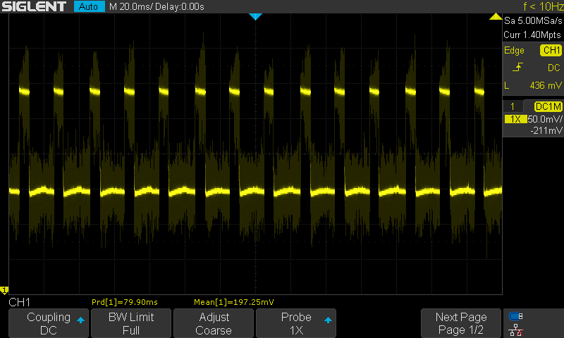
Nearly out of the trigger zone:

Out of the trigger zone:

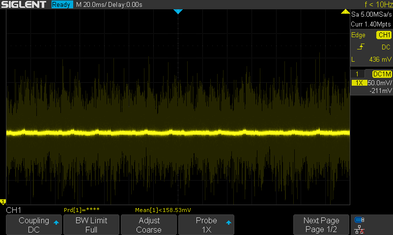
You can see that as I move out of the trigger zone, the peak duration becomes much smaller.

Using the oscilloscope, I was able to see clearly when the sensor was triggered and when it wasn’t. Using that method with my probing method and applying the offset from the dowel pin, I measured the endmill to be 5.934mm in diameter, which is much closer to the 5.94 I measured with my test cuts than it is to the specified 6mm. The difference could even just be due to backlash or microstepping inaccuracy. I think this is not bad at all for a $11 sensor.

I also bought a few other sensors which I’ll try out in the near future.

Of course an oscilloscope doesn’t lend itself well to use on a CNC machine but in the future I’ll hook this up to my machine’s probe input, perhaps with a Teensy or Arduino or something in between to turn a 50Hz signal into binary one. I might also put it in a little automatically opening/closing box or something to keep it safe from chips.

One other thing I’d like to try is measuring runout. Using a wider optical sensor with a deeper “throat”, I should be able to measure the “width” of the tool at the collet holder as well as at the tip and calculate a difference. I don’t know if this will be sensitive enough but maybe.

And the last plan for the near future is calibrating with a better pin. I can get a 6mm gauge pin ground and lapped to ±1.5µm accuracy for 16.20 CHF, so seems like a no-brainer.

Has anyone else tried anything like this before?

10 Likes

@Moded1952 , I’m officially out-nerded, I bow before you :joy:
Very interesting approach!
When all is said and done, do you think you will be able to better control tight tolerances this way rather than using the good old “retry and adjust” method ? i.e. once you can measure the actual tool diameter precisely, you are still left with machine/tool deflection (granted, light finish passes may reduce that to a small enough factor that you take them out of the picture)

That’s an idea for the next generation BitSetter & CM: not only measure tool length, but also tool diameter, then compensate in G-code automatically :slight_smile:

4 Likes

That’s the hope! I think I’ll certainly be able to control tolerances better than the way I’ve been doing it (which was “pray and hope for the best, why bother measuring?”) but whether I can do it as well as or better than the retry and adjust method, I don’t know.

As you say, I expect light finish passes will mostly eliminate the deflection issues.

My biggest worry at the moment is imprecision in the X and Y axes. The anti-backlash nuts and the backlash they’re not good enough to “anti” is one thing but there’s also imprecision in the leadscrews themselves and in the stepper motors’ microstepping.

Some more fuel for the ballscrew fire…

On another note, I’ve been thinking of replacing the remaining parts of the Nomad’s frame with (very heavy) Aluminium extrusion and bolting linear rails and ballscrews to it. Should be a “cheap” way of doing the upgrade that keeps coming back to me (though it would mean my Nomad ceases to be a Nomad).

2 Likes

Just spit-balling here, but is it possible that the people who sold you the 3mm endmill may have actually sent you a 1/8" endmill? Your measurements are closer to 3.175 than they are to 3.00, and are actually off from 1/8" by as much as you measured your 6mm being off…

3 Likes

Yes, that’s very much a possibility, I was thinking the same thing. This endmill was actually a bonus and came without any specs at all (even a diameter). I just assumed it was 3mm.

Hmm. I don’t think you can? At the g-code level you wouldn’t know which way to compensate (what is “inside” and what is “outside”), so this is really up to the CAM that generated the toolpaths, I think.

I’m watching this topic, as I’m interested in dimensionally accurate parts. What I intended to do is some experimentation and a setup for verifying tool diameter using modeling/tooling board as stock — this material cuts easily, isn’t very expensive, and is dimensionally accurate.

I really like the optical sensor approach. I didn’t think those things are that accurate. It would be interesting if there was a way to easily calibrate this thing — I don’t have a micrometer. Those precise gauge pins could be a good solution!

2 Likes

I’ve spent a good amount of time looking at this and testing optical sensors. After spending a few weeks in it I concluded you won’t get a better result from a Bitsetter for less cost. The idea of using an optical sensor in this way is great, but it requires a good amount of setup ensuring X and Y are dead on. Then there is the issue with flues as you point out.

You can’t probe using an optical sensor in this fashion without running the spindle. For most users we’d deem this to be hazardous for many users.

In most cases the Bitsetter is accurate to <0.05mm - which can be reduced further with tweaking but as with all precision engineering there are a huge array of other factors that can come into play when trying to hit higher tolerances.

5 Likes

In case you haven’t seen it before, g-code has G40-G42 which tells the controller precisely that: whether the compensation should be inside or outside. Most CAM packages support it, at least for some toolpaths (e.g. Autodesk mainly does it for contours).

Your controller can then keep a little database of tool diameters, so that CAM doesn’t have to worry about it.

Of course GRBL doesn’t support it but more competent controllers do (mine does).

Do you mean the X and Y axis motion systems or do you mean the alignment of the sensor with the X and Y axes? In the latter case, I think calibration should solve any misalignment issues, right?

For the Nomad, this shouldn’t be an issue, right, it has an enclosure?

For the Shapeoko, not sure how clear my idea will come through but you could put the sensor in a little box with a slot in the top, and only spin up when the endmill is in the box, to keep it away from prying fingers.

1 Like

So I hooked up the sensor to my machine and was able to test it with g-code. Here’s a short video for the visually inclined.

First, I wanted to test repeatability. I put a 6mm dowel pin in the spindle, which I measured as 5.995mm in diameter and ran 100 probe routines. Out of 100 results, I got 2 instances of 5.99mm, 7 instances of 6mm and 91 instances of 5.995mm, so a standard deviation of 0.0016mm.

Without recalibrating, I did the same thing with a 3mm dowel pin. I got 13 instances of 2.995mm and 87 instances of 3mm, so a standard deviation of 0.0034mm.

So at this point, it’s looking pretty damn good.

Then I decided to try testing endmills. I tested the “3mm” endmill and “6mm” endmill from earlier.

The 6mm endmill gave me 20 instances of 5.918mm and 80 instances of 5.913mm, for a standard deviation of 0.002mm.

The 3mm endmill gave me 23 instances of 3.098mm and 77 instances of 3.093mm, for a standard deviation of 0.002mm.

FWIW, this is my probe routine:

LogFile probes.txt 1
#3001 = 100
M3 S1000
While [#3001 > 0]
    G0 Z10
    G0 X0 Y-4
    G0 Z0
    If [#5068 <> 0]
        ErrMsg "Probe already triggered"
    EndIf
    G38.2 Y0 F100
    If [#5067 <> 1]
        ErrMsg "Probe failed"
    EndIf
    G0 Y[#5062-0.2]
    G38.2 Y0 F1
    If [#5067 <> 1]
        ErrMsg "Probe failed"
    EndIf
    #3000 = #5062
    G0 Z10
    G0 Y4
    G0 Z0
    If [#5068 <> 0]
        ErrMsg "Probe already triggered"
    EndIf
    G38.2 Y0 F100
    If [#5067 <> 1]
        ErrMsg "Probe failed"
    EndIf
    G0 Y[#5062+0.2]
    G38.2 Y0 F1
    If [#5067 <> 1]
        ErrMsg "Probe failed"
    EndIf
    Msg "Tool diameter is " [#5062-#3000 + 0.434] "mm"
    LogMsg [#5062-#3000 + 0.434]
    #3001 = [#3001 - 1]
EndWhile
M5
M30

However I noticed that the numbers I got didn’t match my test cuts. The 3mm endmill should have been 3.12mm but was 3.098mm (off by 22µm) and the 6mm endmill should have been 5.94mm but was 5.918mm (also 22µm off).

When I tested the dowel pin (and calibrated), I did two probes on each side:

  • Probe towards the sensor until triggered, hold position
  • Probe away from the sensor until triggered at a lower feed rate, treat this second trigger point as the trigger point

But with the endmills, I did it differently, since the probe can’t reliably untrigger due to the spinning endmill:

  • Probe towards the sensor until triggered, withdraw 0.2mm
  • Probe towards the sensor until triggered at a lower feed rate, use this second trigger point as the trigger point

So I tested the 6mm dowel pin with the same procedure and got 5.963mm, which should have been 5.995mm, so was off by 32µm.

If I apply the 32µm correction, my endmill measurements were 3.13 for the 3mm endmill (so 10µm off) and 5.95 for the 6mm endmill (so 10µm off).

However since the offset was consistent, I’m inclined to use the test cuts as the calibration instead of the dowel pin.

I may also get better results if I put something to turn the 50Hz trigger signal into a solid on/off state.

But I have to say that so far, I’m really surprised that a sensor that costs so little can be so repeatable.

6 Likes

That’s the beauty of solid state optical sensor systems, once the design is well sorted they can be dirt cheap, accurate and hugely reliable.

This topic was automatically closed after 30 days. New replies are no longer allowed.