I’ve been doing some test cuts with the #102 endmill trying to check the dimensional accuracy of the Nomad and was surprised to find that my cuts were quite a bit off (by 0.05mm-0.07mm).
I then did some cuts using a 2mm endmill and these were spot on, down to what I can actually measure (0.01mm).
So I took my calipers to the #102 and it turned out that it isn’t really a 1/8" endmill (3.175mm), it’s closer to 3.12mm.
I’m having trouble wrapping my head around how that is possible and how nobody notices? Is that just the one endmill that I have? What does your #102 measure?
You can’t accurately measure the cutting diameter of an endmill with calipers. Calipers can be used to measure the diameter of cylindrical objects but the geometry of an endmill is too complex. Just look at it from the side and look at what the calipers actually have to measure. If you measure perpendicular to the endmill shaft, there are hills and valleys in the profile as the flutes go up and down. If you measure parallel, there are at most two single points on either side you can hit and if you’re even the tiniest bit off parallel, you’re measuring a thinner area.
In machine shops, they generally use an optical comparator for a task like this.
For us, the best way to measure it is to do test cuts (e.g. mill a square pillar) with high radial engagement but very very low axial engagement and see how far off it is. High radial and low axial in order to reduce deflection.
It’s pretty common to see small variances in tooling. Even when you get into the expensive tooling high end machines use tooling compensation and will measure the diameter using a high end Renishaw probe or similar. It’s not possible to do on this level of machine but you can tweak tool paths to achieve a high tolerances such as 0.05mm or higher.
I would add that measuring a end mill with callipers won’t give you an accurate measurement. As I type this @Moded1952 just chipped in with some good info.
Unfortunately Carbide 3D doesn’t publish tolerances.
Bringing me back to @jwr’s question: apparently it’s possible for an 1/8" endmill to be up to 0.05mm undersized, so you could expect a 50µm discrepancy to be within tolerance, so it could be responsible for some of what you see, particularly if your outer dimension is larger than you expected, or your inner dimension is smaller.
Other things I’d look to are runout (you can measure it with a dowel pin in the spindle an a DTI on the side of it) and deflection.
And one big question: in what direction is the discrepancy you saw? Are you seeing more cut than expected (almost certainly runout) or less (endmill diameter or deflection)?
This could be because you’re using a smaller endmill, which has a tighter tolerance (Harvey Tool specifies +0.00/-0.02mm for 2mm endmills), because you’re cutting lighter with a shorter endmill, minimizing deflection, or because you’re using a different collet.
I do realize that it’s difficult to measure and endmill with calipers: it took me a while (and many tries) to get a result. You can get quite close by rotating the endmill while it’s in the calipers and trying to find the size that stops it from rotating.
I also measured several other endmills that I have (2-flute and 1-flute) and got results accurate down to 0.01mm. The only tool that is off is the Carbide3d #102.
@Moded1952’s answer about the tolerances is very interesting — I had no idea about those, especially the negative -0.05mm, which seems like a lot. And it could very well be that smaller endmills have tighter tolerances.
The discrepancies were while cutting modeling board, so in a pretty relaxed setting (finishing contour pass was at 24kRPM, 500mm/min, removing 0.5mm radially with a depth of 2mm). I do not suspect significant deflection with this kind of cut. My circle-diamond-square results were consistenly larger than expected (so, less cut), hence my suspicion of endmill diameter.
And I don’t think this is due to deflection or rigidity, because I just cut some acrylic with a 2mm endmill using rather aggressive speeds and all the sizes are spot on.
I guess I could set up another test, cutting a slot, and perhaps even (heavens forbid) a hole.
But are you sure the measurements are accurate, or do they just match your expectations? If I’d handed you those endmills without any context, do you think you’d still be confident in your number?
I’d try it with 2mm radial, 0.5mm depth just the same. I can’t speak for the Nomad 3 but the 883 Pro may as well be made of jelly and you want to minimize the forces on the cutting plane as much as possible.
It seems like a lot out of context.
First bit of context: 0.05mm is around the edge of general machining tolerances for example the most stringent (fine) DIN ISO 2768 general machining tolerances are ±0.05mm, so twice as wide.
Second bit of context is that no matter what tolerance the endmill holds when you buy it brand new, the diameter will be reduced as you use it and it wears.
And last bit of context is that many (most?) machine shops have an optical comparator with which they can measure the endmill themselves and compensate for the diameter, or they have a diameter probe inside the machine which runs before every job.
Manufacturing precise endmills at scale is expensive (e.g. here’s a catalog with endmills that hold a 0.02mm tolerance, ~$38 for a 3mm endmill) and most people who care about precision need to deal with wear anyway, so have the capability to compensate for variance in diameter, so it really isn’t a bit deal that the endmill has an 0.05mm tolerance to begin with.
Quick preface, I’m with PreciseBits so while I try to only post general information take everything I say with the understanding that I have a bias.
This is for a number of reasons. First, is that we are dealing with centerless ground blanks to make tooling from. These start out smaller than the actual shank size (about 0.0002" / 0.005mm). Then you have to add margin drop, grind flutes, an edge, and possibly add reliefs. So even if you had perfect blanks, grinding machines, and wheels the tool would be smaller after you add the minimum steps to turn it into a cutting tool.
What that functionally means is that there is a looser tolerance on any tool that has a cutting diameter the same as the shank. In many cases this is also why you see a +0,-X spec on those tools and a ± on all the tools less than the shank size.
There is a way to solve this problem by starting with a larger blank then post grinding the shank to the correct diameter. However, this adds a LOT of cost and can make the tool less accurate as the shank you were using to grind the tool is being modified and can lead to tool runout.
Not only is it not possible to get the actual cutting diameter this way (margin drop, relief, etc) but very easy to damage the tool without realizing it. One of the big issues is that to get the tool to not rub you grind away material behind the edge. This means that the only way to measure it with calipers “accurately” is to measure on the edge… the weakest part of the tool. You WILL damage the tool measuring it this way. Might not be enough to see or make a difference in the next few cuts but it will make that part of the edge wear faster as it is now fatter from dulling or chipping it.
Hope that helps to explain some of the issues. Let me know if there’s something I can help with.
No problem, I’m glad it was useful. Reading back through it, I might have come off a little aggressive on the caliper thing. Glad it wasn’t taken that way though, wasn’t my intent.
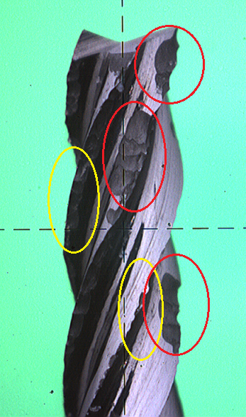
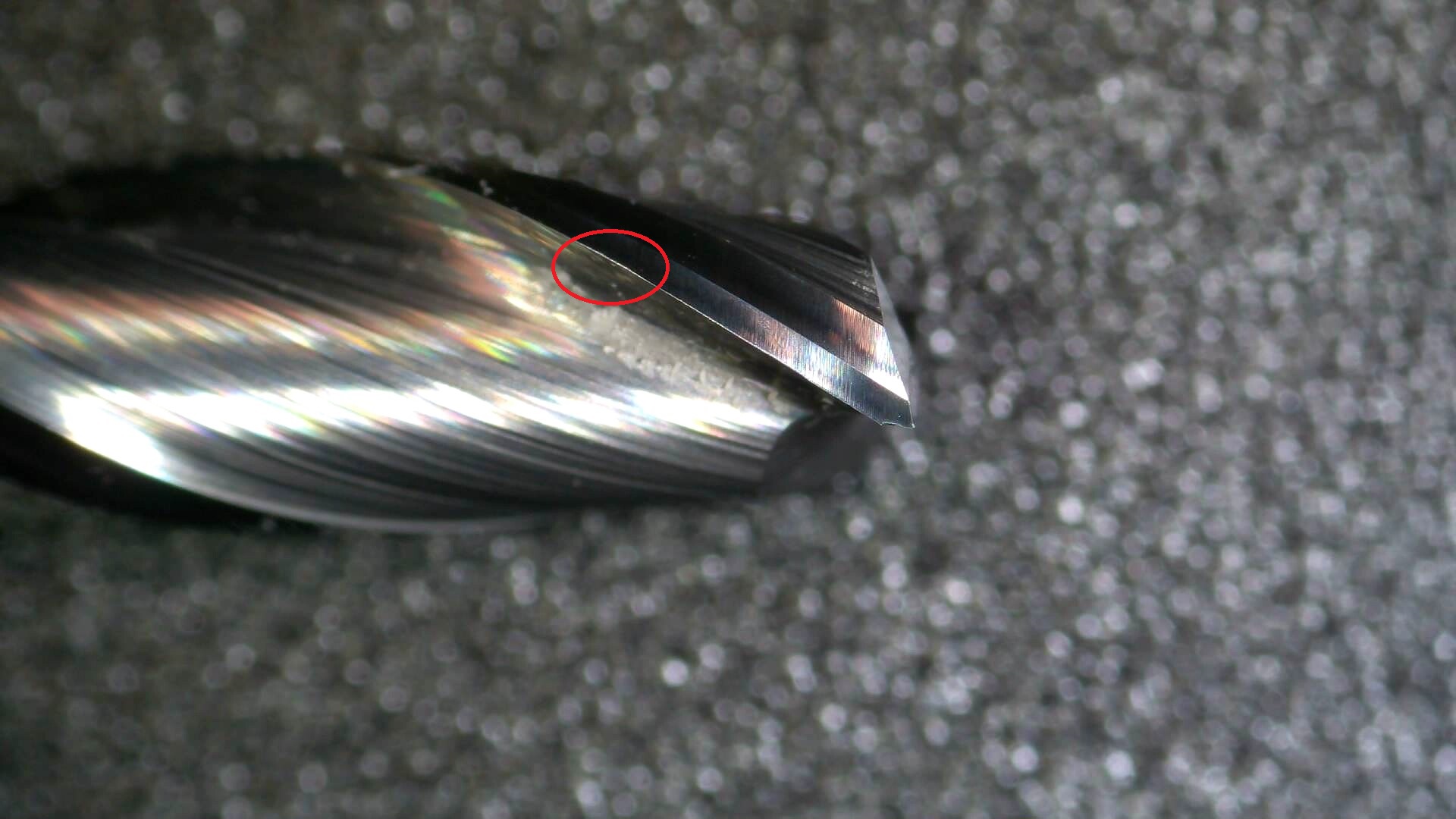
Just to give a visual here’s a picture of a tool a customer sent back because it was “too small”. Keep in mind the diameter of the tool was 0.0280" (0.71mm). So most of this was not visible without a microscope. I believe them when they said they didn’t know the tool was damaged.
The kind of damage we normally see when someone uses calipers and turns a tool backwards is what I circled in yellow. The type that’s typically caused by closing calipers down on the edge of a flute are in red.
The tool’s still usable and the other flute will clean up the cut mostly. Going to cut into it’s life though. Regardless of the reason the tip damage was recent. Breaks like that start to burnish pretty quickly even in wood.
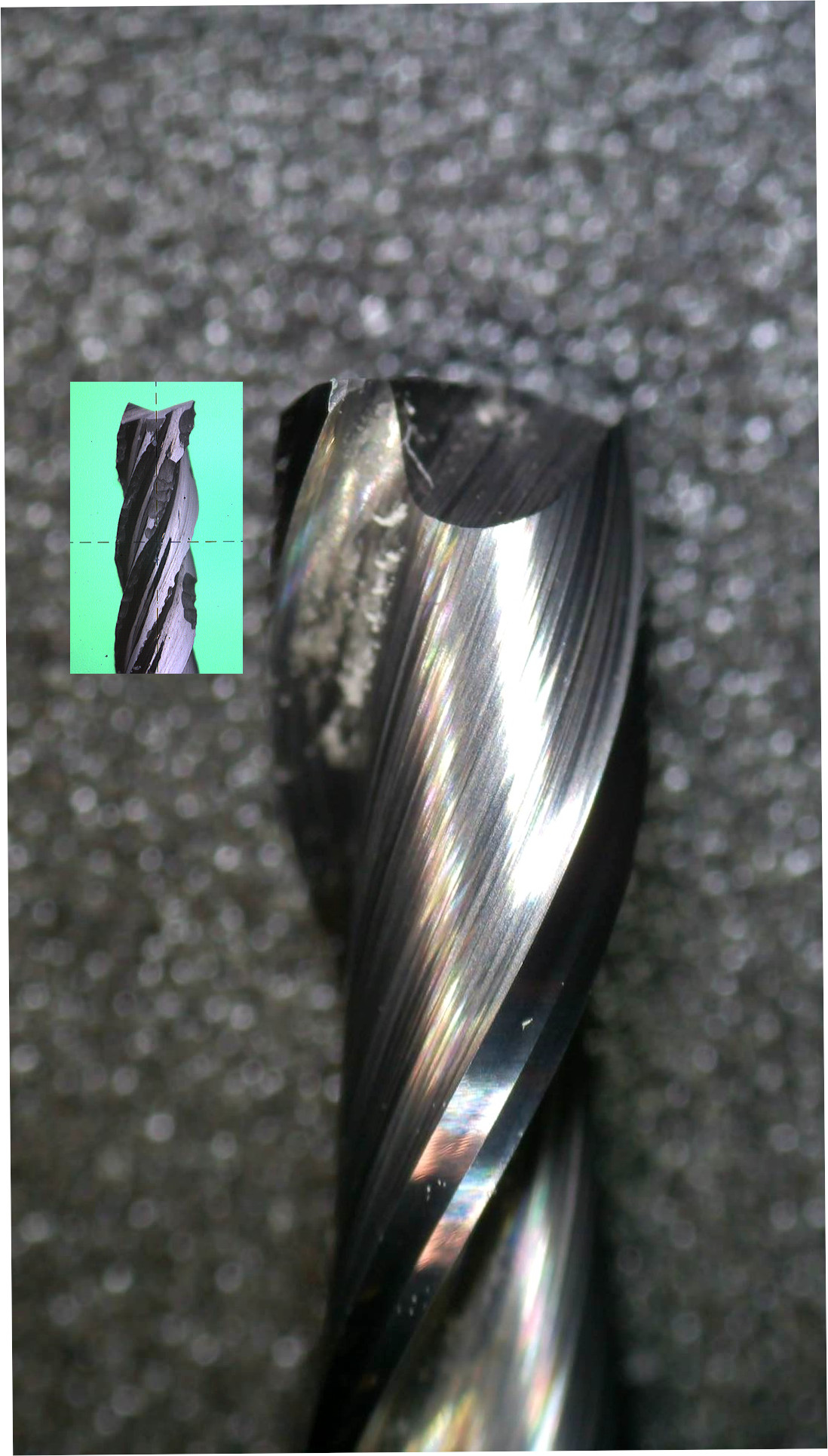
Don’t know the reason but you do have accelerated wear on the tool in one place. Easier to see zoomed in. There’s another less obvious one on the other side in the other picture. Looks a little further up the tool.
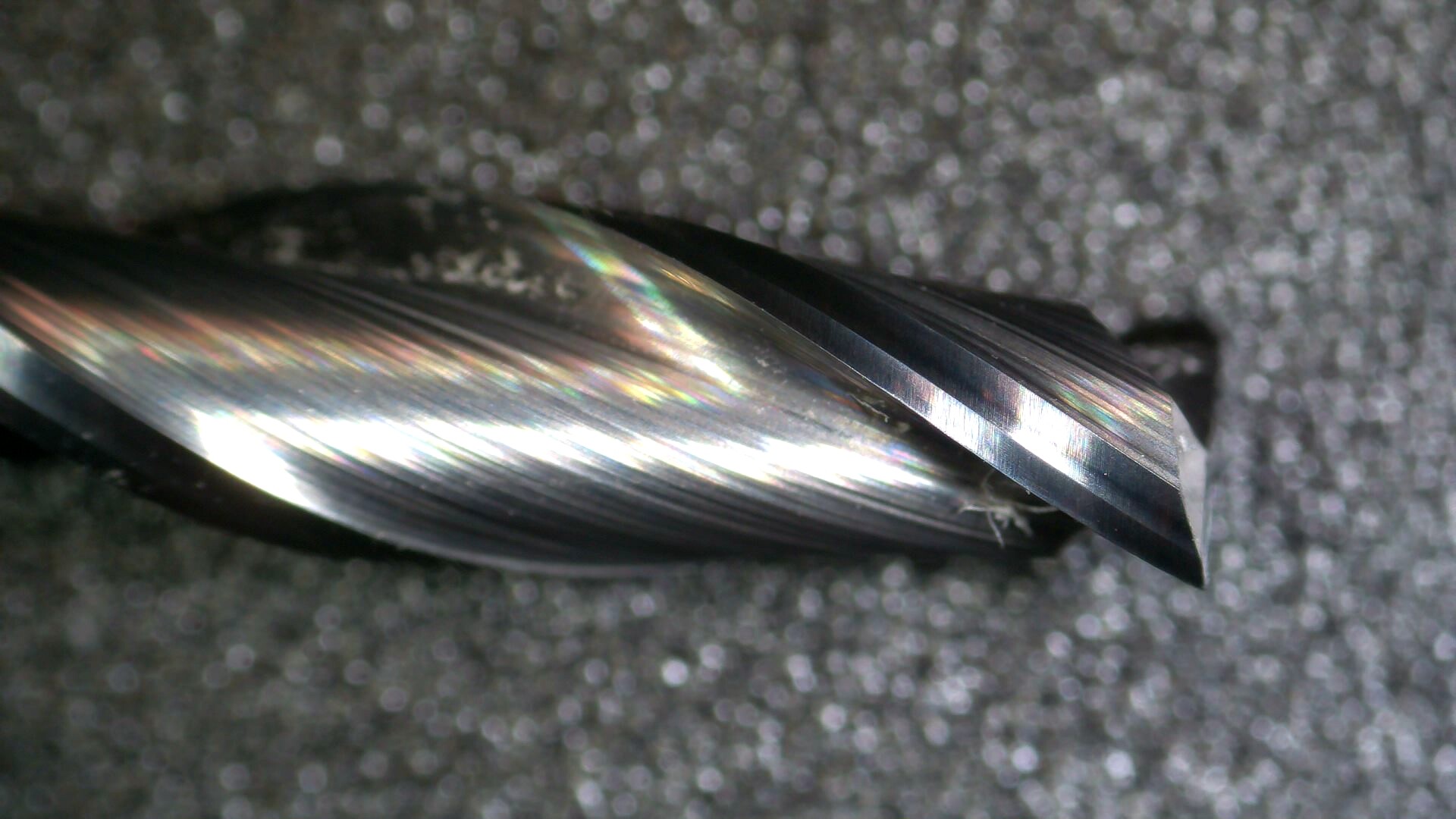
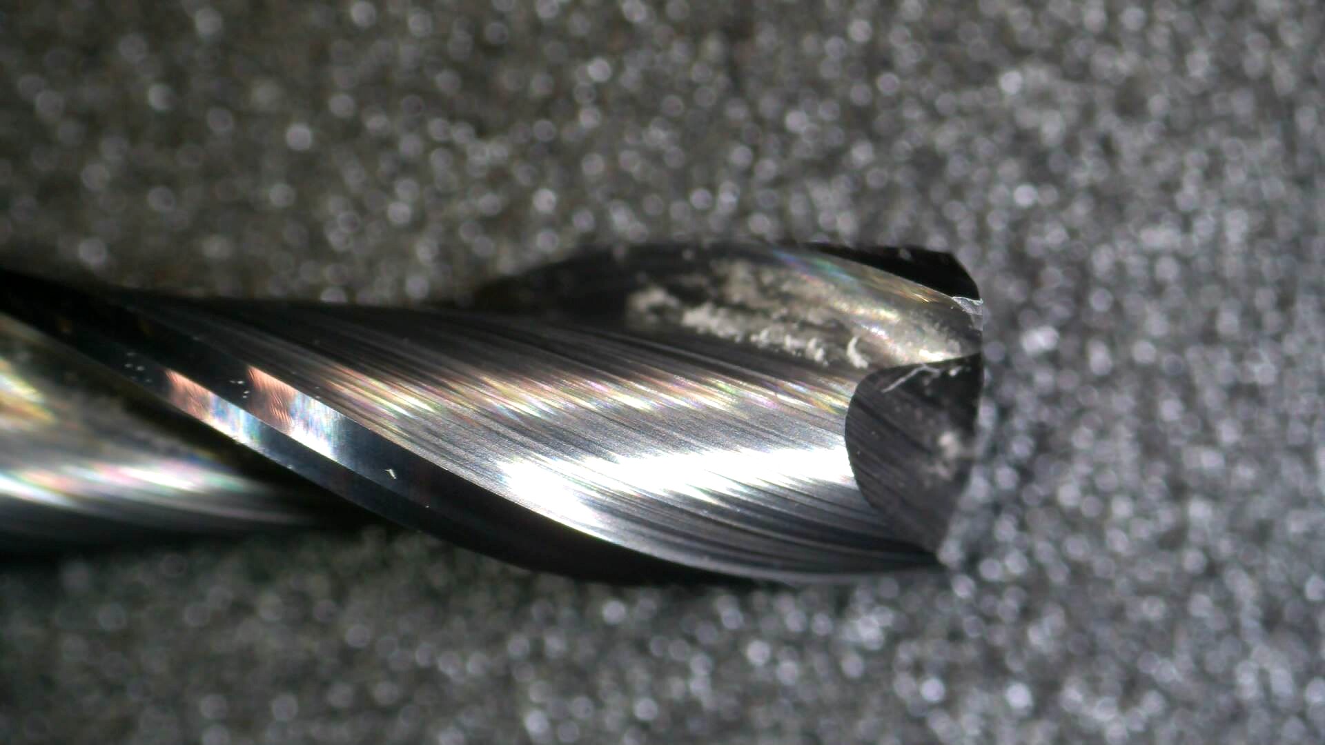
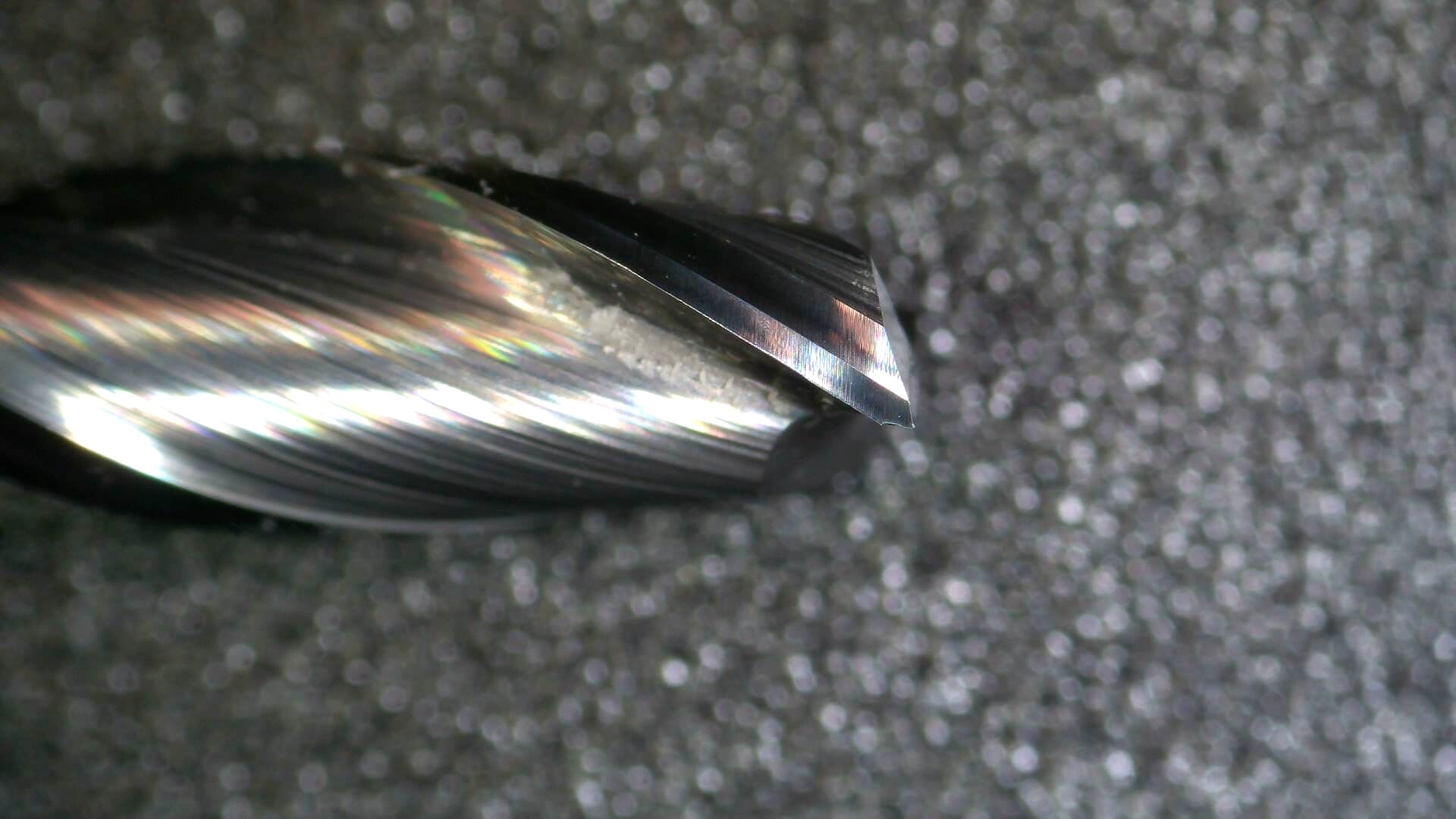
Just for comparison here’s mine scaled as close as I can pixel measure to yours. Starts to make more sense why they didn’t notice the damage before sending it back.
Apologies for the somewhat odd-topic diversion but can either of you microscope-wielding folks recommend a magnifying device for inspecting endmills? Even better if it can measure them somehow.
Interesting — perhaps that’s because of my (apparently not entirely featherlike) caliper operations. The tool hasn’t seen that much use, and only in soft materials (softwood, acrylic, plywood, HDPE).
@Moded1952 I use an inexpensive Chinese HDMI scope. I mostly bought it because it can be used as a long-throw magnifier if you don’t use the full magnification. I normally have it mounted about 50cm above my desk, for electronics work. For these pictures, I put it on its stand. It can magnify more than in the pictures above, but I don’t find that useful with 3D objects, because of the shallow depth of field. I think this is what I bought: https://www.aliexpress.com/item/4000580264781.html?spm=a2g0s.9042311.0.0.556f4c4dcoWQnz (although with products from China you can never be sure). The software has some measuring options, but I couldn’t get anything to work, and I’m not sure if I could trust those measurements anyway.
Honestly it depends on your budget and resolution needed. For visual measurement we use Mitutoyo tool maker scopes and binocular scopes with digital camera heads. The one used for that picture was an old Motic camera. It’s software functions, frame rate, and resolution was quite limited. We switched over to Touptek a while ago (they are the OEM for a LOT of scope cameras). They have much better software and cameras from our experience. Again, depending on the price probably the easiest to use entry point would be a Amscope with a camera. Their cameras are also Touptek so get whichever is cheaper if you go that way. Use the Touptek software though.
The other issue you have to deal with in measuring is calibration. So you need some kind of standard depending on accuracy required. More specifically you need a similar standard as a flat one won’t work for calibrating a round object. Additionally, the size taken up in the field of view and light will cause small changes and the edges are useless. There’s also depth of field issues which is a whole other problem.
Might be, if it is, it’s a higher tungsten content carbide (they are, all other things being equal, tougher but softer). That will cause more rolling of the edge than chipping. It’s still carbide though so that’s relative.
 )
)