I’m having what looks to be the identical issue to that shown here.
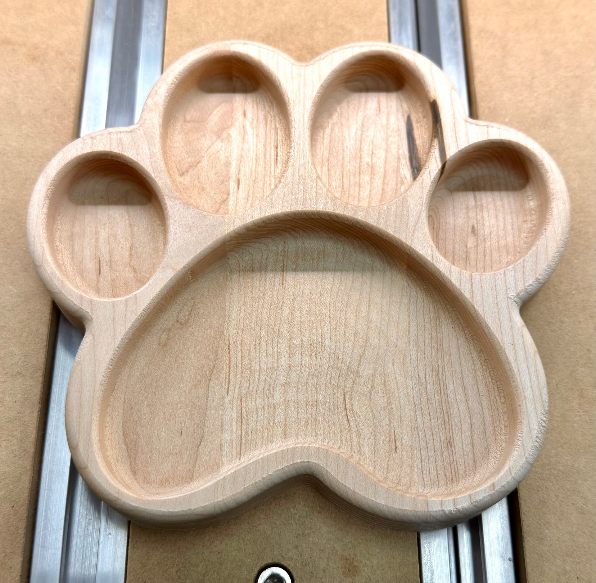
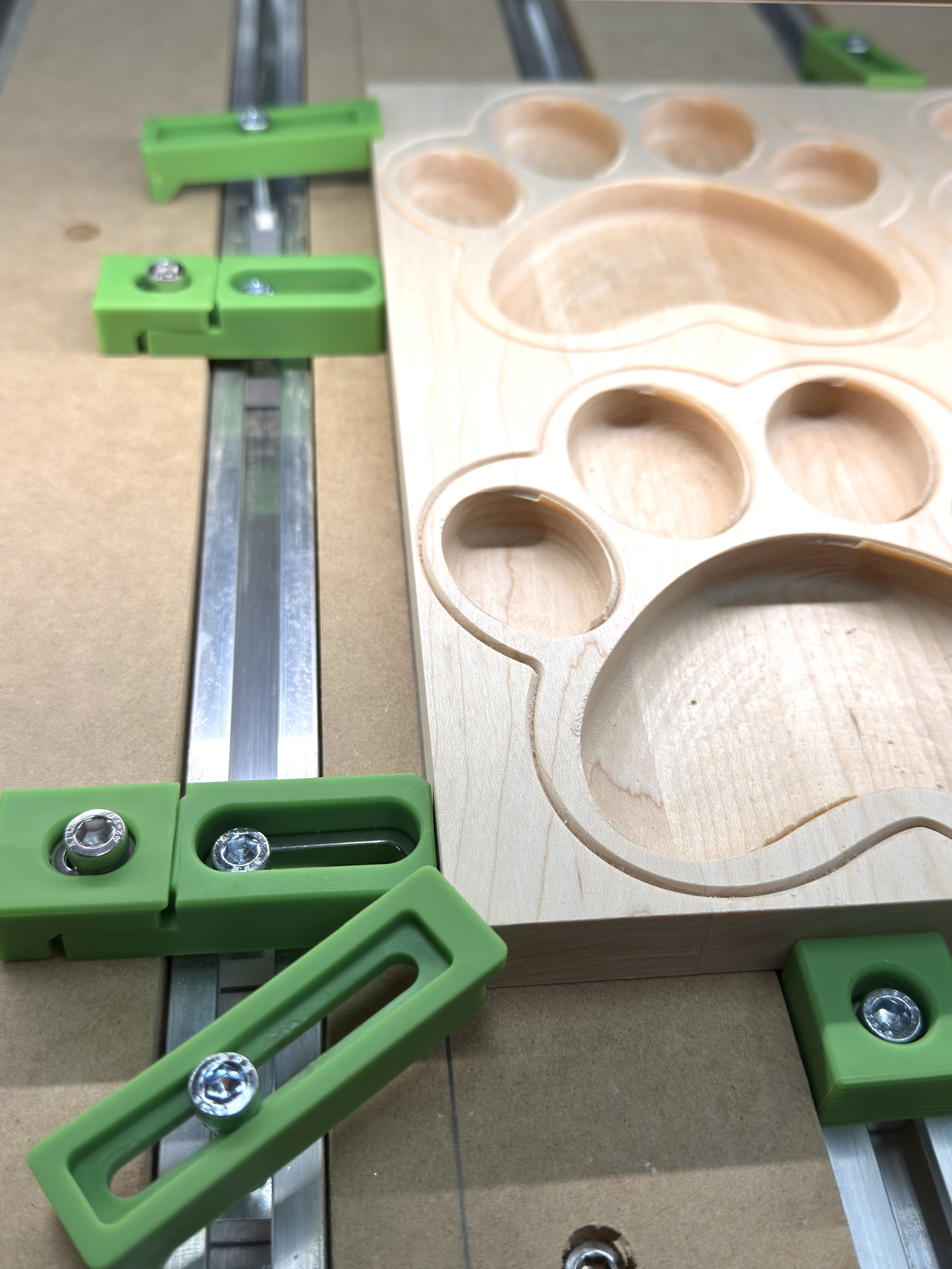
I have a new Shakpeoko 5.1 Pro (just received it the day before yesterday) and am doing my first cuts. I did a single paw print tray (designed in Create Pro), and it was perfect (inside and outside roundovers, pocket roughing cuts, pocket finish cuts, and outside all as expected).
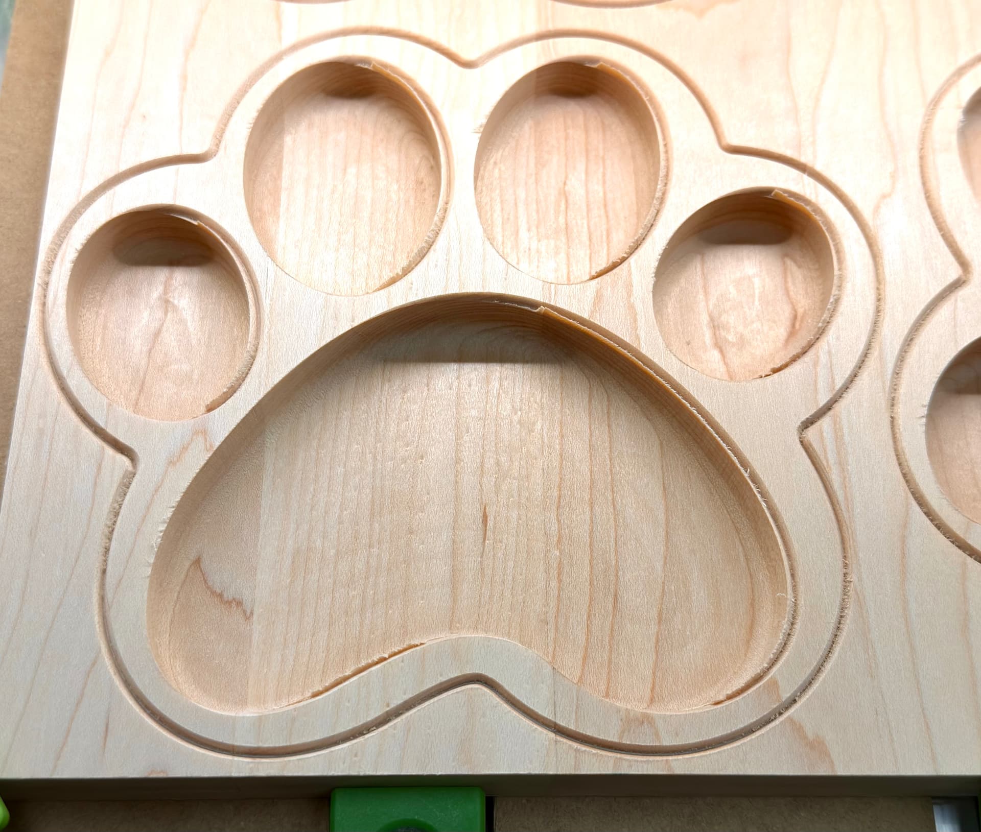
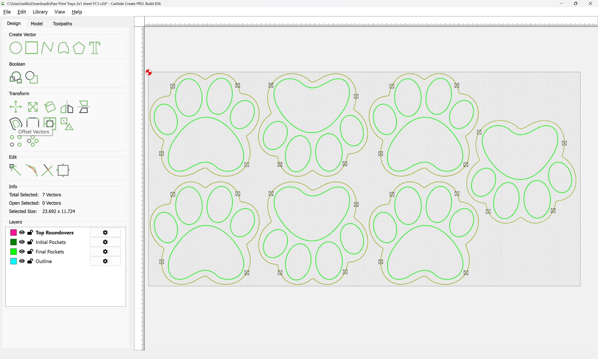
I duplicated that set of vectors (with toolpaths assigned to the vectors, not layers) to make seven of these on a larger sheet, and started the job. The roundover cuts are all in the correct places (measured to confirm), but all subsequent cuts, including roughing and finishing pockets, and the outside boundary, are offset left about 1/32" (I’d estimate .03" – .05"). There has been no movement of the material; it’s locked down solidly.
Does anyone have an idea what might be going on?
Was there ever a clear solution for the issue in the referenced post?
Thanks much!
Bobby
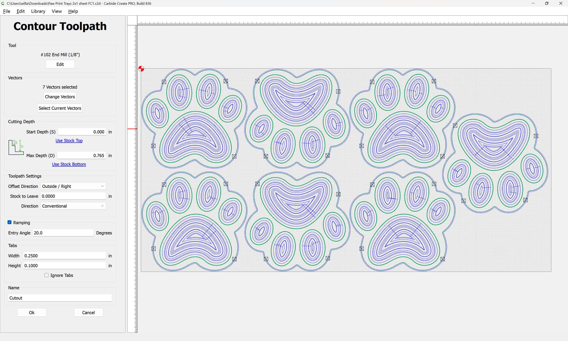
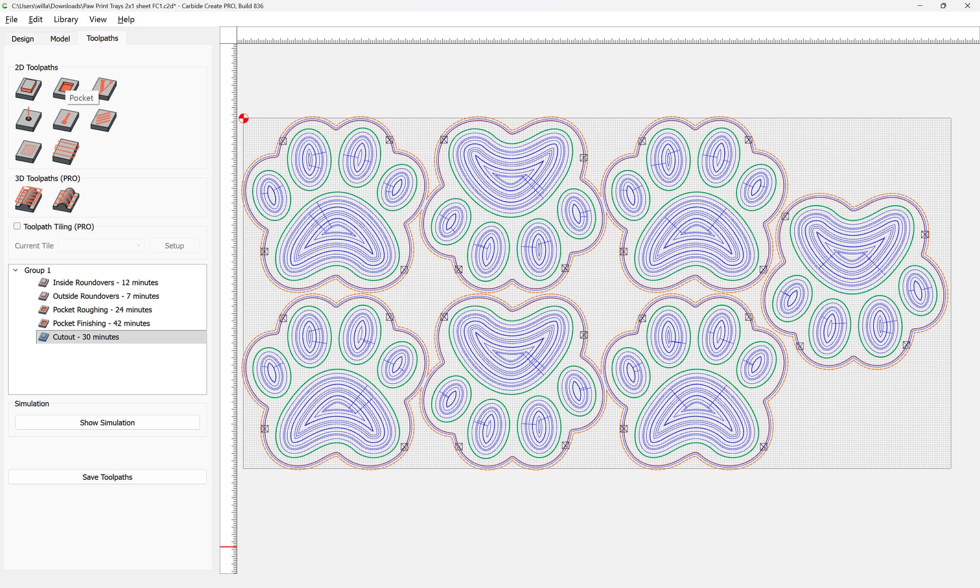
PS: In case anyone thinks some of the vectors may have been dragged “off-center” of the rest of the design during the duplication process to create the larger batch job, I’ve included a photo that shows the design in Toolpaths view for reference. All of the vectors are concentric as expected.
The usual suspect is a mechanical problem. Depending on what machine you have. An SO3/SO4 might be belts or stepper motor pulleys loose. A SO4 Pro and SO5 the linear bearings may be dry and need lubrication. Looking at your picture if it was cut in that orientation it would be an X problem.
For all machine it could be a dust collector hose got hung up.
Depending on your F&S you could be losing steps if cutting too aggressively. Looks like maple and some maple is very hard while others relatively soft.
If I had to bet I would bet on mechanical. Bearry Scarry
For troubleshooting the cut, face off the stock (or flip it over?) and try cutting again, this time keeping a close eye on things and maybe setting up a video camera to monitor things?
If you’ll upload your file we can review that with you.
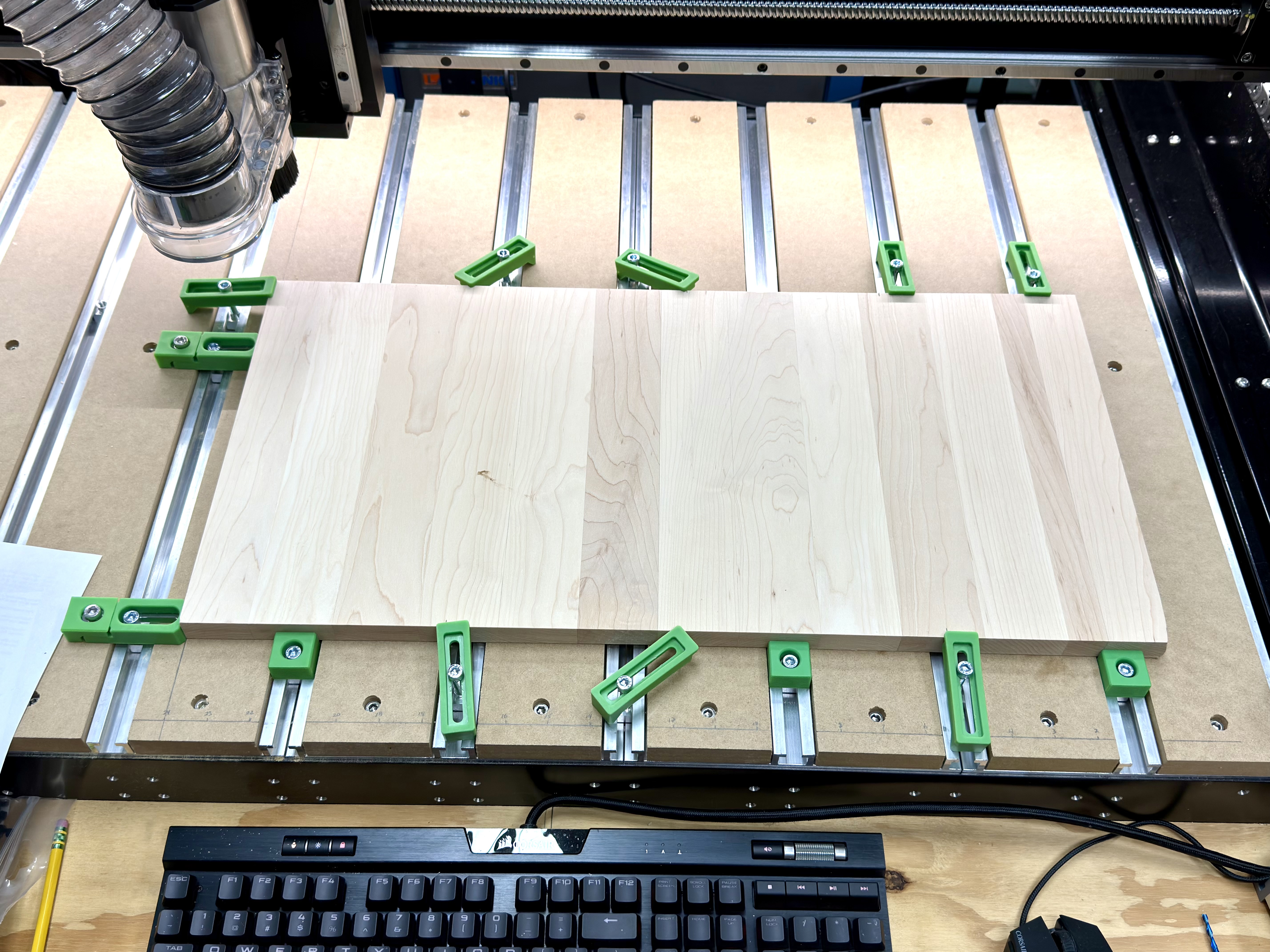
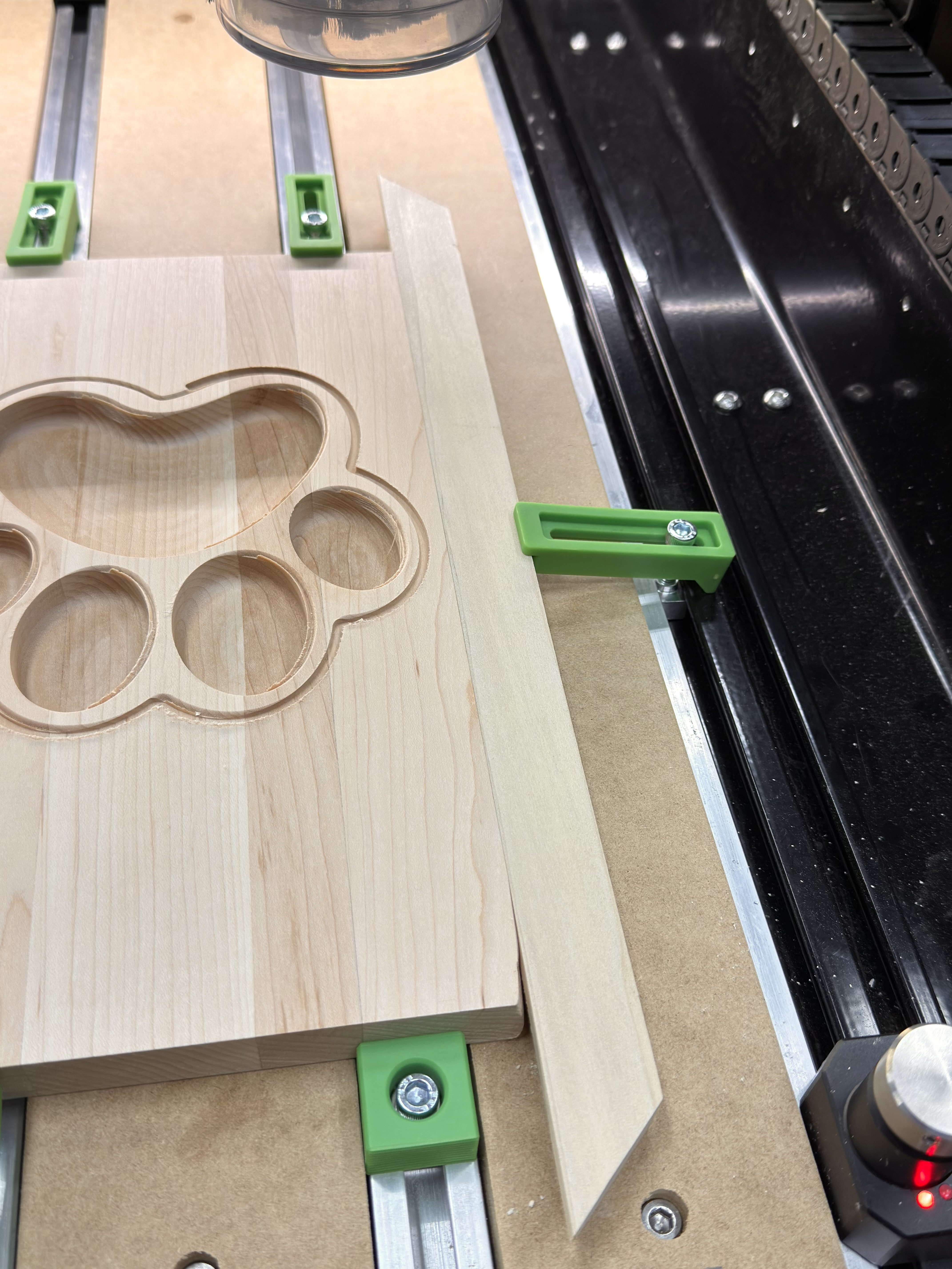
Based on this photo if the cuts shifted left as the program ran first thing I’d check is did the stock shift right. There are no clamps on that edge to stop it moving in that direction. In other words the program is cutting in the correct place but the work material is gradually moving under it.
The waste piece to aid clamping is a good idea. If I’m in doubt I run the program on a test piece first but I know that isn’t always possible. Failing that for something mostly 2.5D, you could create a separate program to run all the same toolpaths at .010" deep zeroed of the spoilboard. You can’t test a radiused edge that way but it should show if the profile and pockets are aligned or getting distorted. Since you’re shape is curve it’s very hard to measure. If I really thought it was a mechanical movement problem I’d get a large sacrificial piece and run a basic geometric pattern program like a grid where the spacing of cuts can be precisely measured.
I’ve flipped the wasted piece of maple over and I’m rerunning the job. So far, no offsets. AFAIK, I’m doing things exactly as before, so it’s an unsolved mystery.
I’ll load up a new blank and give it a run. It’s “only” wood that I’ll be wasting if it glitches again, right? ¯_(ツ)_/¯
by endmill diameter plus 10% — I’d also recommend sourcing a tool which has a cutting flute length of at least 3/4" — the #102 only has 1/2", so for the bottom 1/4" of the cut, the shaft rubs, resulting in friction/heat, then cut as a pocket down to tab height.
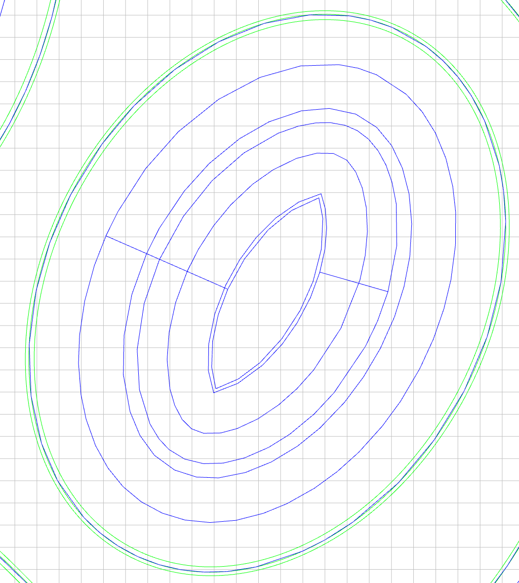
The three vectors are intentional and work as intended, other than in the job run that lead to the original post.
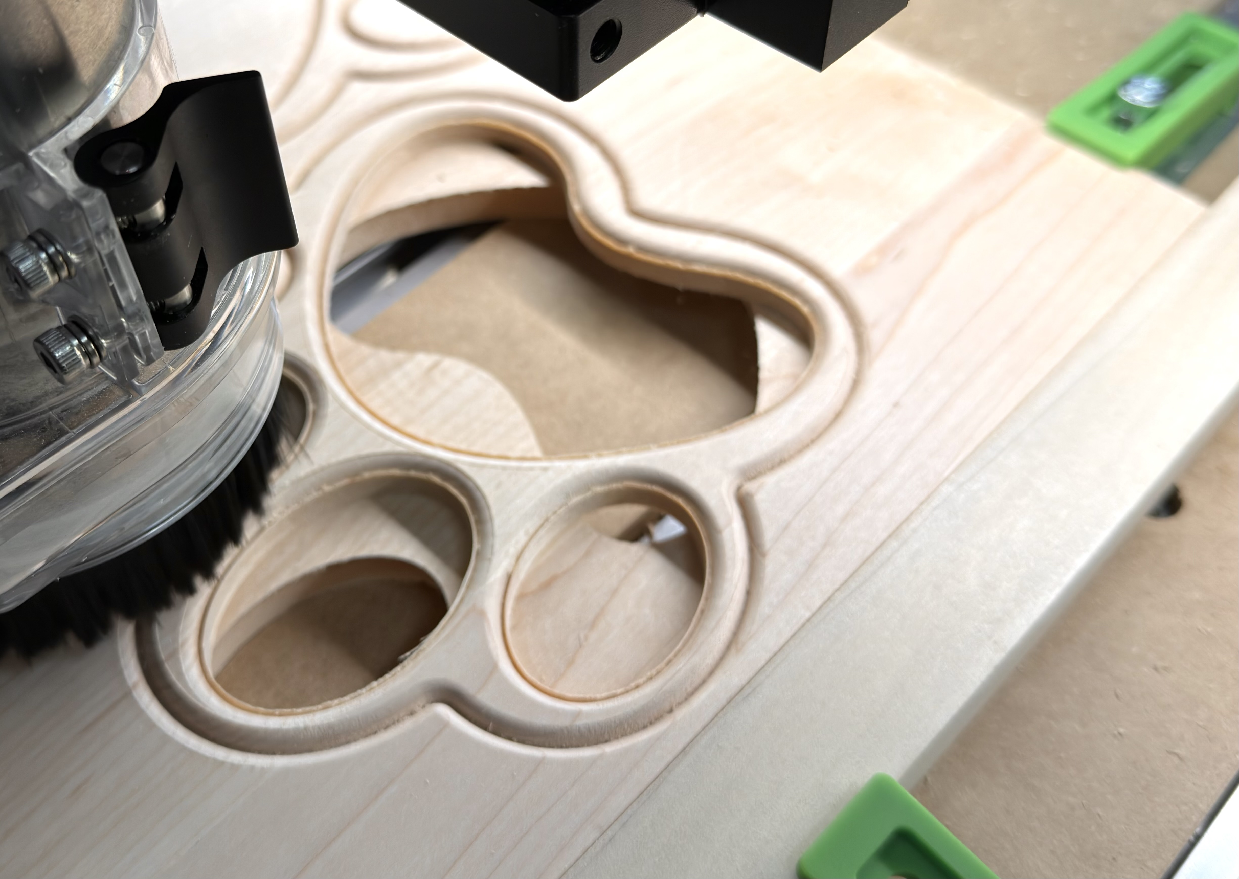
Outer ring: final pocket cut with a tray bit
Middle ring: point round over bit (needs .015 to not gouge vertical face of tray)
Inside ring: roughing bit pocket (leaves .03”)
Thinking back through my workflow, I’ve identified one difference in the job that went sideways: I sent it from Create running on a different computer.
The job is running fine when loaded to Motion locally.
Thanks for the detailed feedback. I’m actually using a 1/8” cutter that has a 1” cut length. I was too lazy to create a new tool.
I’m also stepping it down slowly.
BTW, I’ve used this same bit (not literally, but several of the same brand and design) to make hundreds of items with the same stock. It saves quite a bit of wood for product rather than sawdust.
The problem with cutting a slot with high tooling engagement is that it works, until it doesn’t — it’s best practice to avoid that situation, and the cut sounds much less stressful, which helps one to be able to monitor the machine.
Another potential issue is that cutting hard maple causes a lot of vibrations running back thru the gantry. This can affect the wiring harness connectors causing intermittent connection loss & inexplicable lost steps. The X & Z motor connectors are the most susceptible. Be sure to check that they are not getting strained by other cabling/cable tray or vac hose brushing up against them. Zip ties are great for securing them down so they aren’t flopping around in mid-air.
You can check if the connectors are problematic by gently flexing/fiddling with them while jogging the axis - if there’s any stuttering/stalling/grinding then that means the connectors are not making proper contact 100% of the time. Heavy machine vibrations are likely to cause lost steps during program runs. I’ve had issue with both my X & Z connectors on my SPROXXL over the last couple years which lead me to replacing the connectors with aviation style connectors. Some people find just zip-tieing the connectors tight together ensures a solid connection. Others have cut out the connectors & hard-wired the motors in for maximum reliability. Be advised that C3D is unlikely to replace a wiring harness under warranty which has been modified.
My explanation is that cutting slots as narrow as the tool tends to result in random behaviour when high tooling engagement results in lost steps — if one wants a process for reliable operation, and to avoid lost steps, avoiding slotting and high tooling engagement is one step.