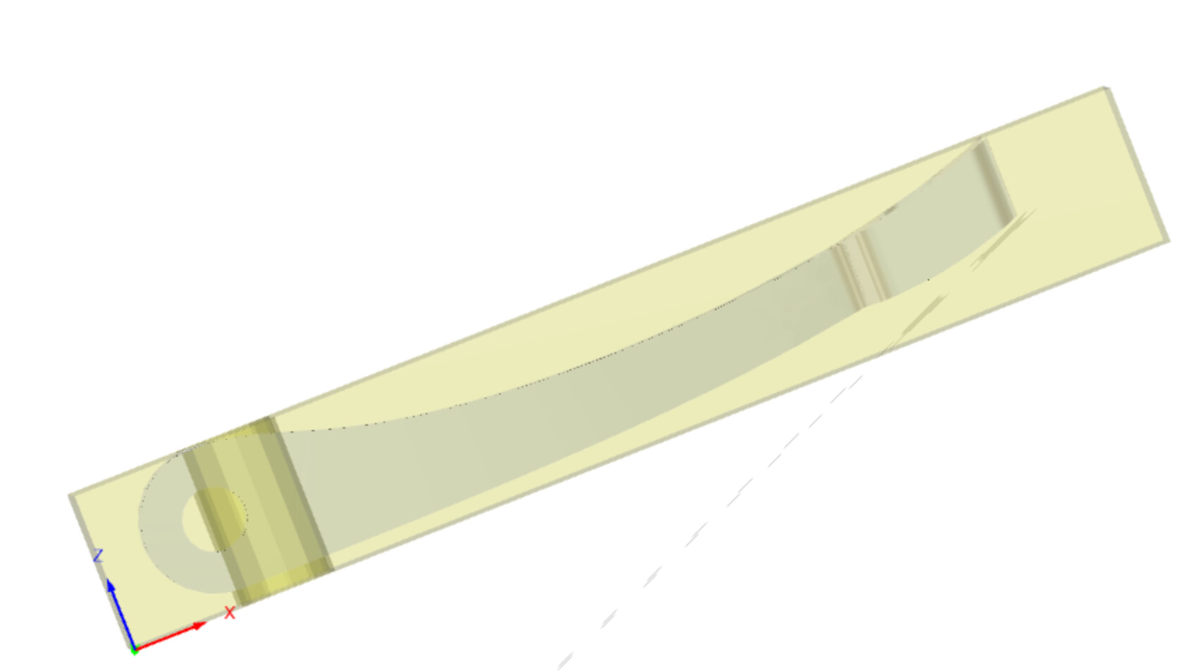
A question for the metalheads out there. I’ve got a part I’ve designed such that all the surfaces (except two round holes I will drill afterwards) can be done from two sides, top and bottom from 10mm plate as stock.
The geometry is not very complex, the sides are all vertical and I plan to use a ballnose on a parallel toolpath to get the curved top and bottom faces. I have spare stock with setup toolpaths to put locating pins through for the flip when the top is complete and I need to turn it over, there’s spare stock to leave at the edges for it to stand on when I flip it. I plan to blue tape and superglue it down for workholding.
My problem is that as I cut the piece out of the 10mm plate, how and where to leave it connected to the stock?
Would you limit the contour depths to leave a gap?
Or actually model in some tabs or a long thin slice to connect to the stock?
I’m planning to cut it out after flipping it so the ops are
1 - Drill and bore the locating holes, square the stock externally, insert pins and re-zero
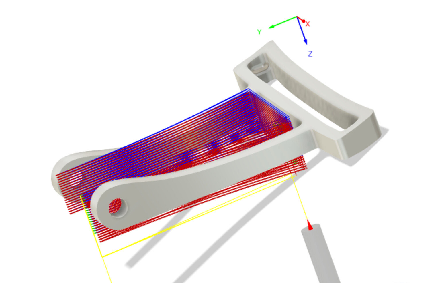
2 - Adaptive clear above the piece, contour the slot parallel the top curved face with a ballnose
3 - Adaptive clear, parallel the bottom curved face with a ballnose, then contour down as far as I dare and find out when it starts to vibrate too much to give a decent finish
Have you done much work in aluminium before? If so good, if not, I’d try to tackle a few jobs before I’d have a crack at this one.
I’d drill three or four dowel pin holes in a block to start off with - and also prepare a fixture plate with corresponding dowels. It’s kind of a pity to do all this for one part - but it will make your life much simpler when you do the flip over.
You are aware of Meshcam? If not: http://www.grzsoftware.com/ Best thing since sliced bread or perhaps cheese. It’s great value, and once you own a license - there is no risk of some nasty corporation changing the rules on you later on!
Check this out:
The work piece would be held in place with a few tabs - that are manually removed once the job is done. Where the tabs go, how big do they need to be - that’s where a bit of practice would be good. To few / small and the part flies off when its 98% done, to many / big and it’s more effort to remove and finish up. So a bit of wax-on wax-off Mr Miyagi style would go a long way before you go big time.
Of course you’d do a rough cut (not a ballnose), then do a finishing pass with a ballnose. Then flip over and repeat (with the B side tool paths)
Again, practice doing roughing / finishing passes to get the finish required before you start doing flip overs.
I don’t like tabs (just because I’m clumsy, and always fail to do the manual clean-up well enough that it is not visible), so I would do the following:
mill side A
mill a jig (from MDF or whatever) that is the negative of side A, including locating holes
flip the part onto the jig, use locating holes to align (of course), using tape & glue to hold the part in place on the jig
mill side B
I have done it to mill a wavy 2d sided wooden piece, but the principle could be used for metal. Maybe using a couple extra holes to be able to screw the flipped side A onto the jig, if tape&glue is not adequate.
I’d go with tabs (which Fusion offers as an option as part of the contour operation IIRC) or a fixture, like Julien is suggesting.
The fixture would be the cleaner, nicer option.
However for fixing the part to the fixture, I’m not sure tape and glue will be enough, because your part doesn’t have a huge surface area and the cutting forces for aluminium are higher. Instead you’d want some kind of clamp built into the fixture, like these.
I already have some locating pins to flip the stock. I’m going to try some tabs first and see how I get on. At the moment I’ve got most of the top stock face left intact which may be enough for me to tape and glue it down over the pins. If that doesn’t work then I escalate things and start machining out fixtures to clamp it in.
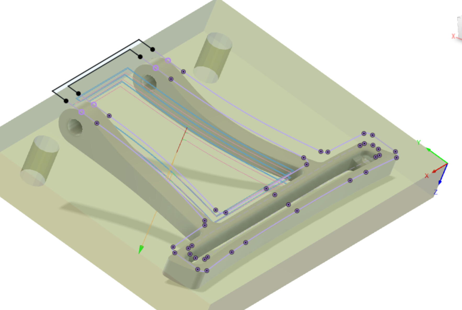
I’ve found that creating a sketch and projecting the outline(s) of the part into it allow me to join them up or extend them into selectable contours that I can easily use for a 2D contour path, the shape itself doesn’t have contours that select nicely for this. It seems odd to be projecting the solid that I built from various contours back onto a plane as a contour but it makes the CAM quite a bit simpler.
Here for example the ‘inner’ and ‘outer’ contours are separated but both joined up into complete paths that don’t result in a back and forth contour cut doing both climb and conventional.