Wavy bamboo surface...but where do I go from there?

I was quite pleased with how the back of my latest trivet turned out, so to avoid making YET another trivet I tried something else, something abstract, that would serve no purpose (other than being cool, hopefully).

TLDR: skip to the last pic and tell me where you would go from there.

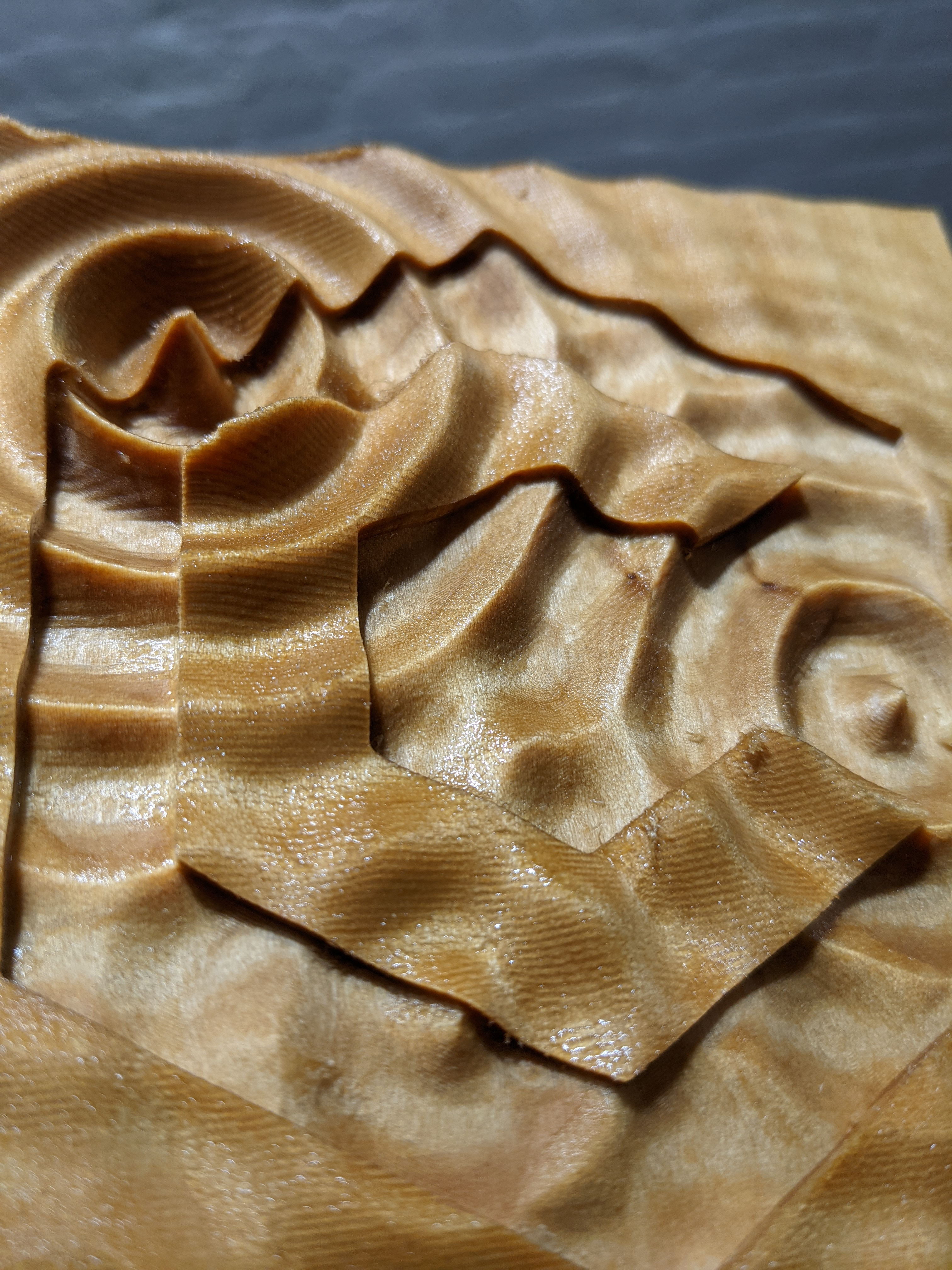
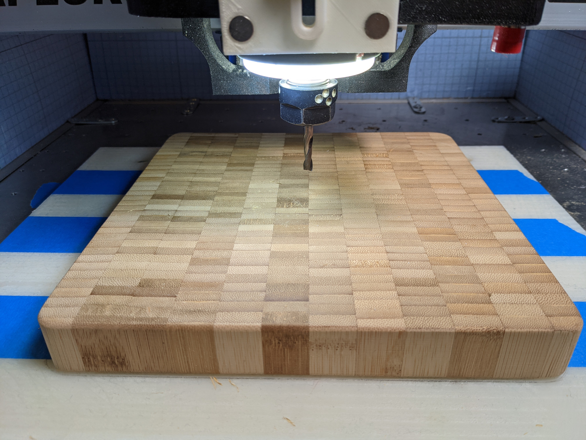
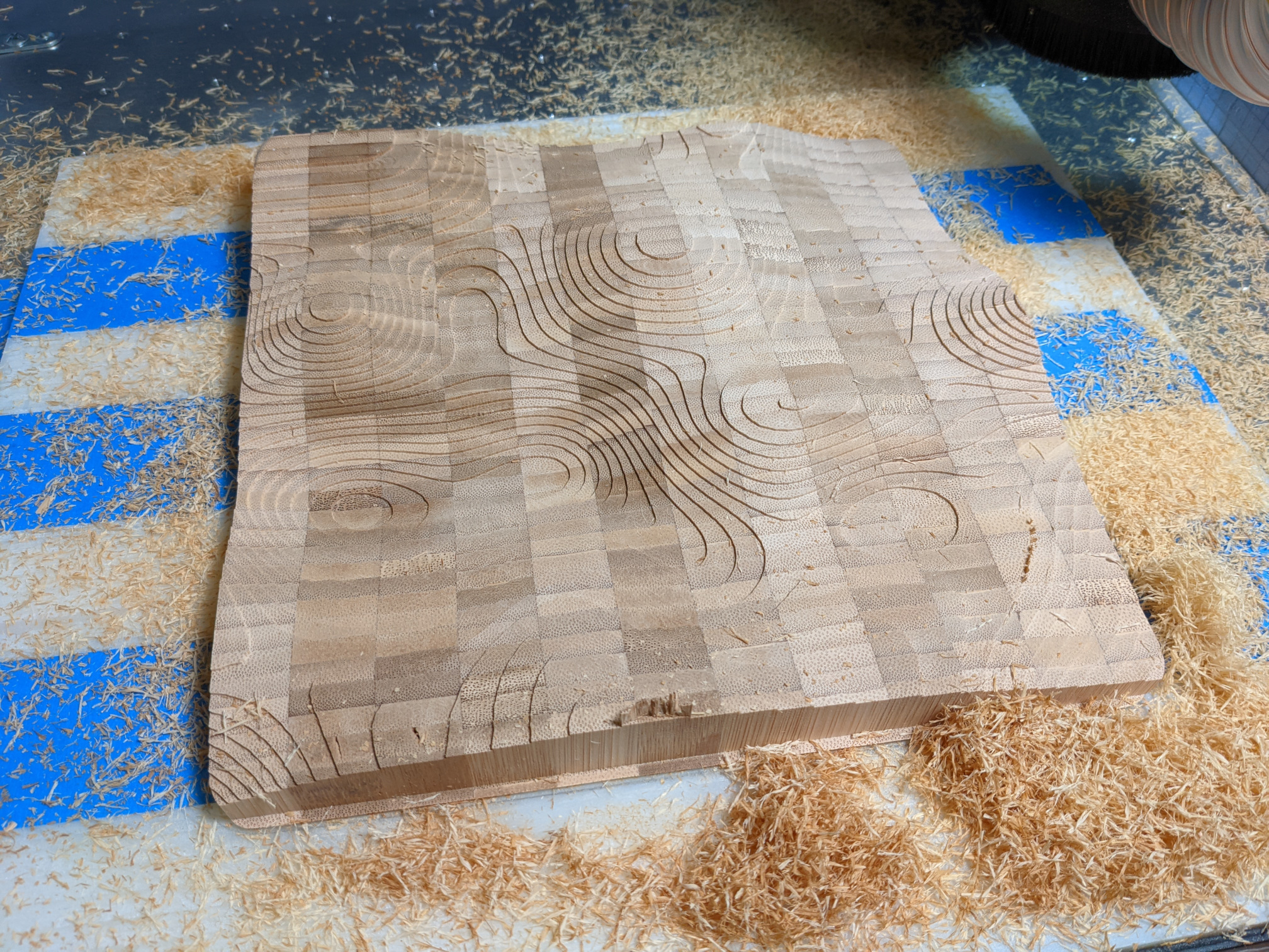
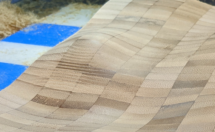
So I started with this nice thick block of “endgrain” bamboo again:

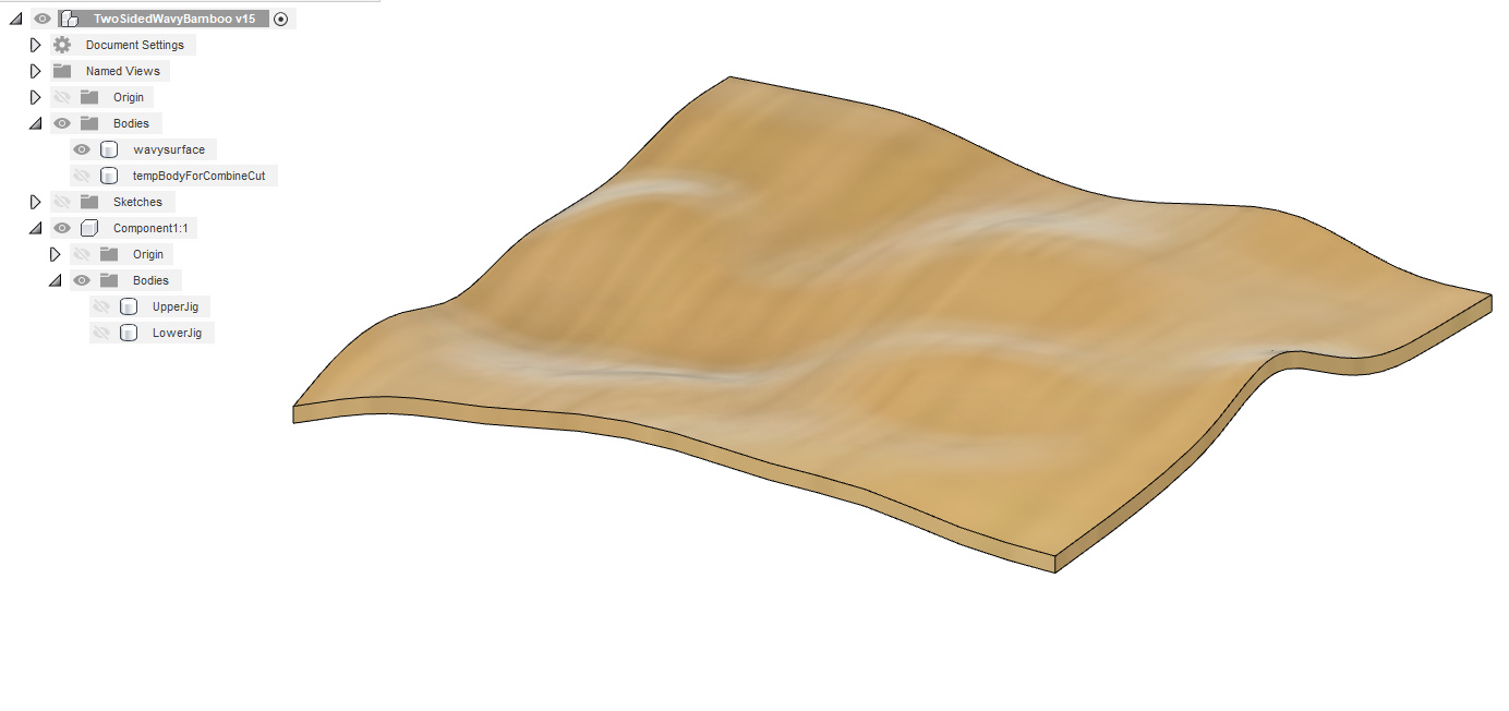
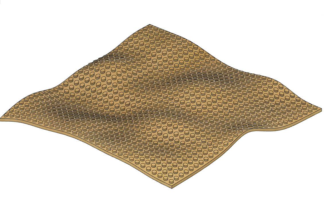
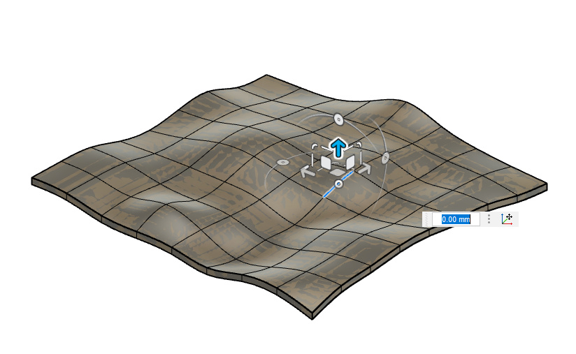
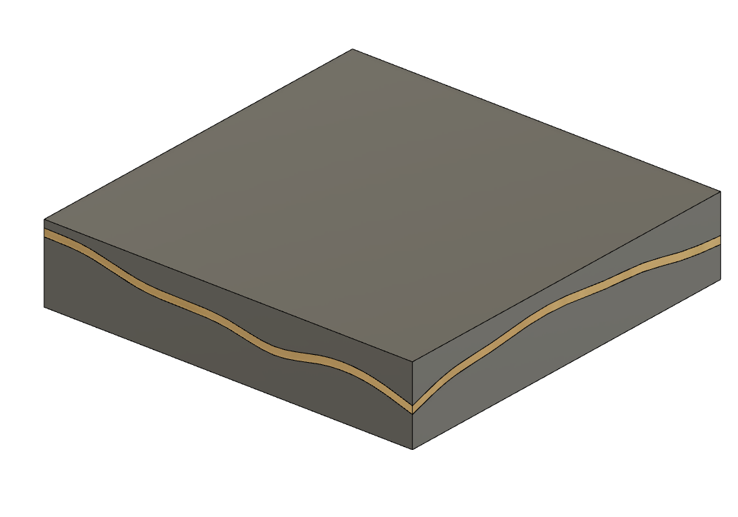
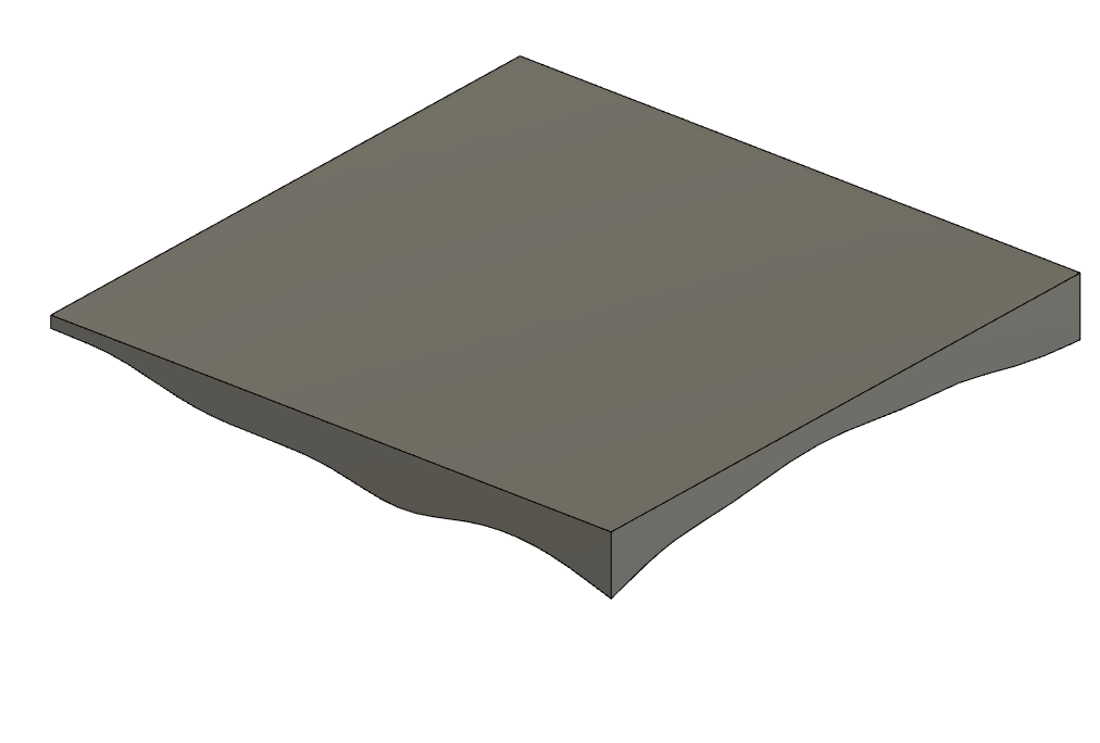
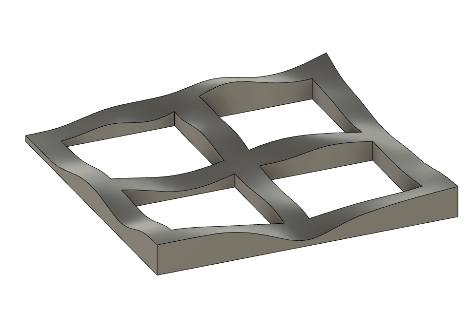
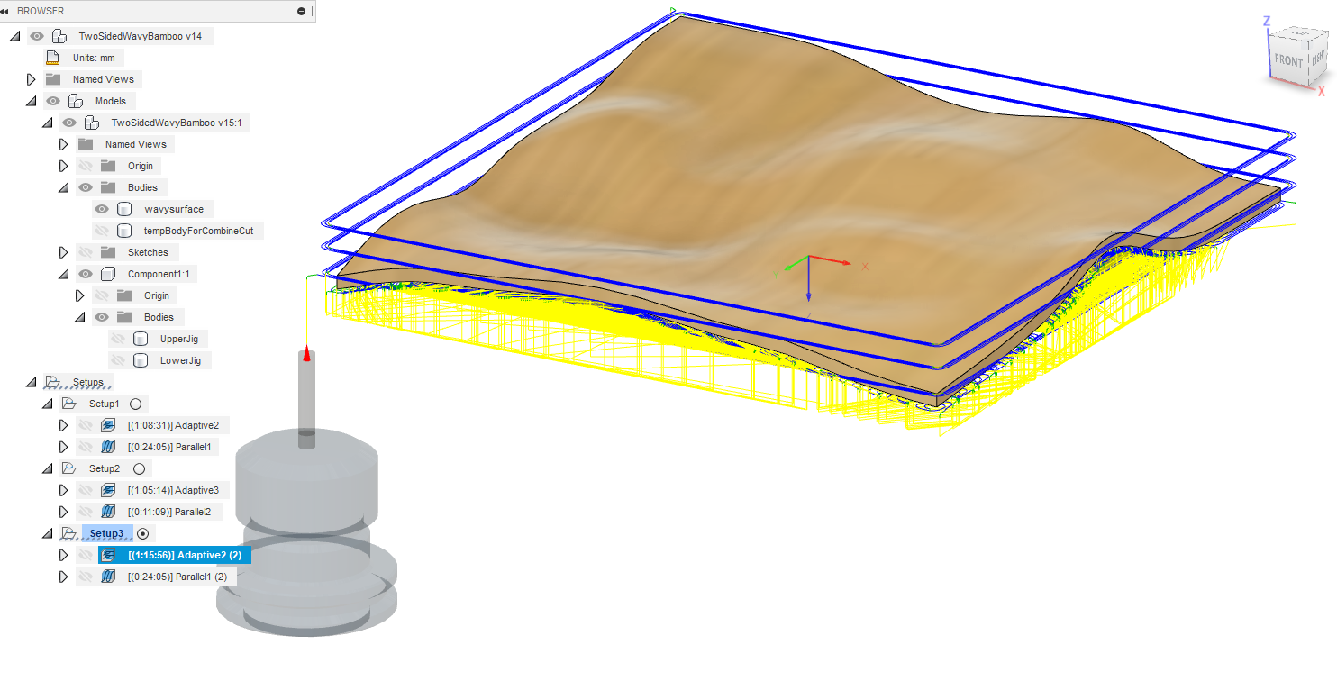
And figured I would play with Fusion360 form edit mode again, started from a Plane, subdivided it a few times, pushed/pulled on edges using the Edit Form tool, and thickened it to a 5mm solid, till I got this:

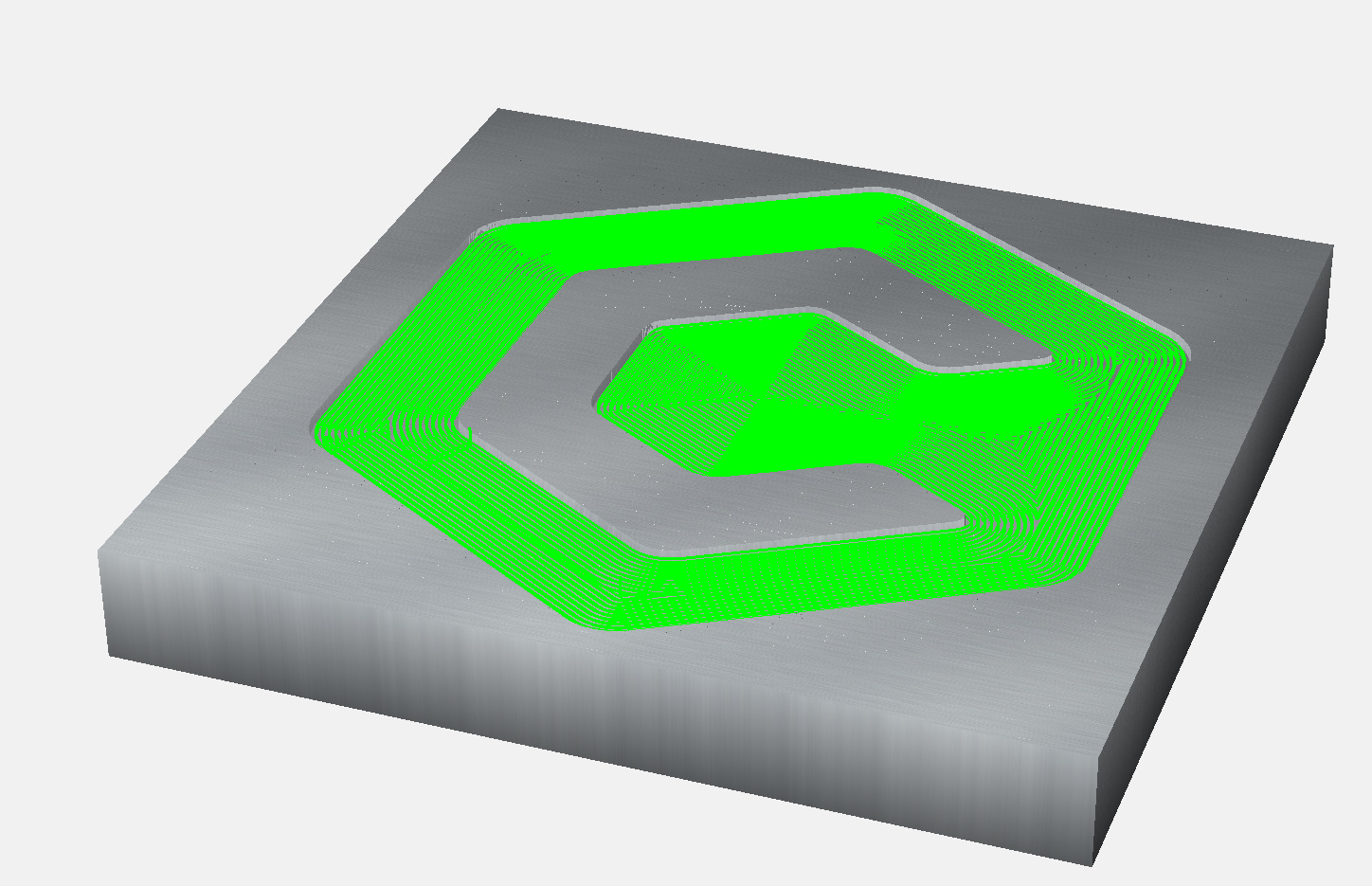
The roughing cut for the top face was easy,

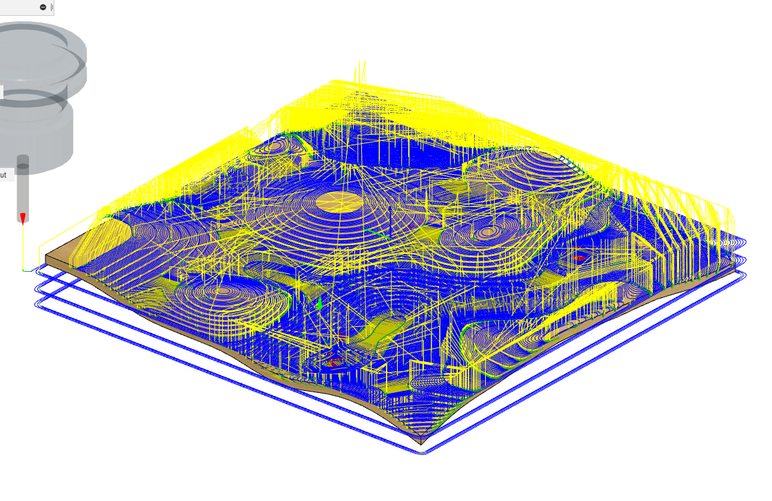
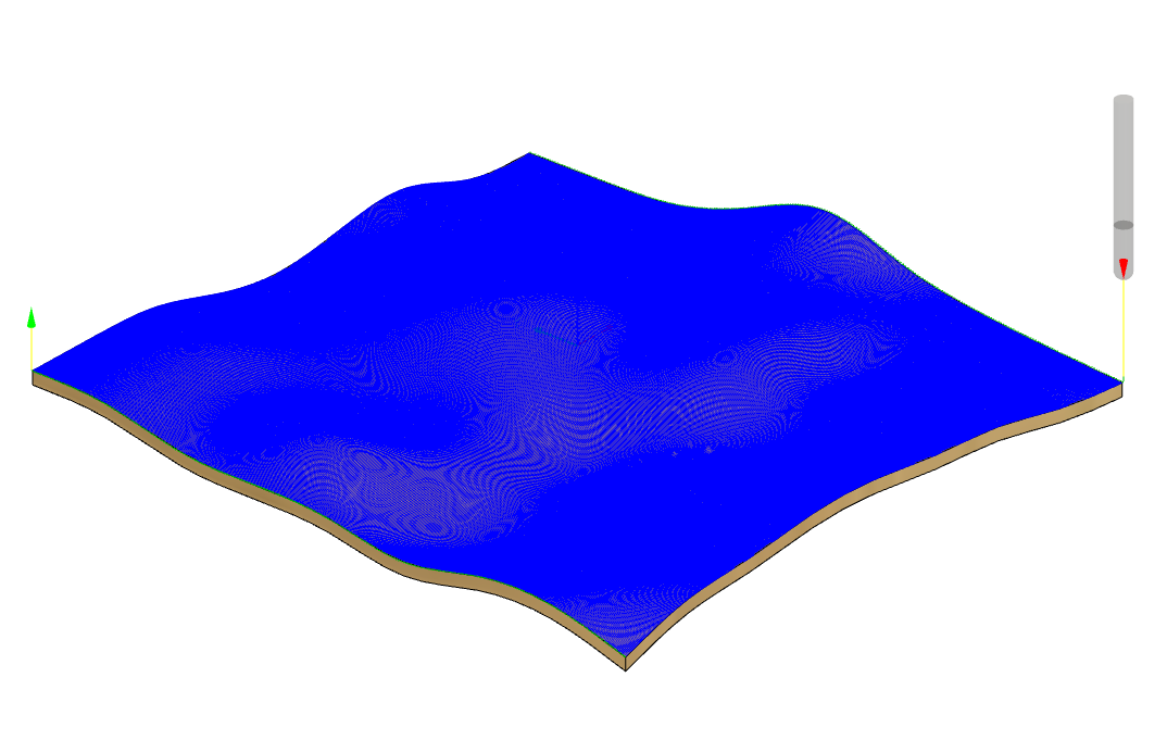
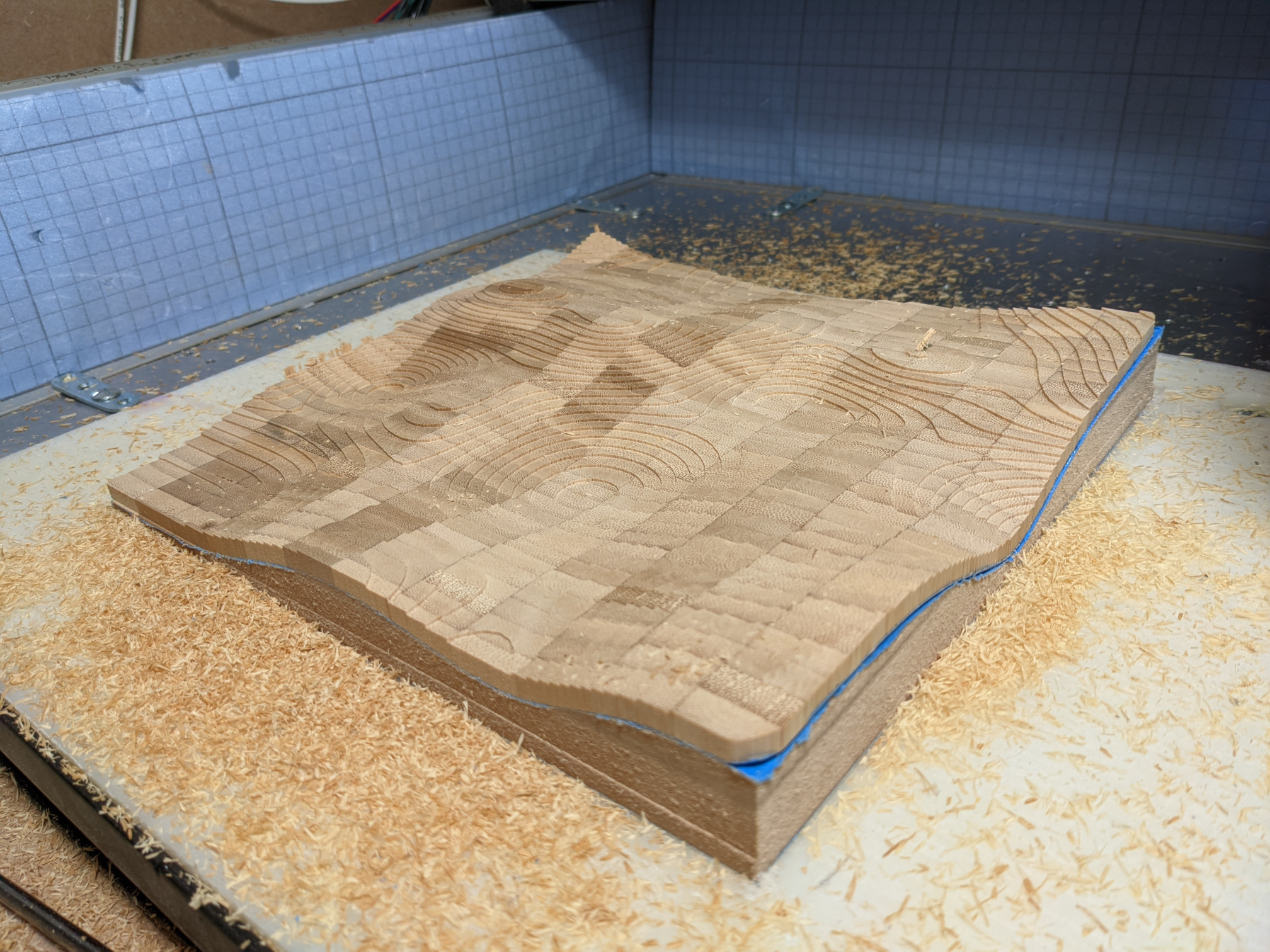
And parallel finishing worked fine on such a continuous surface,

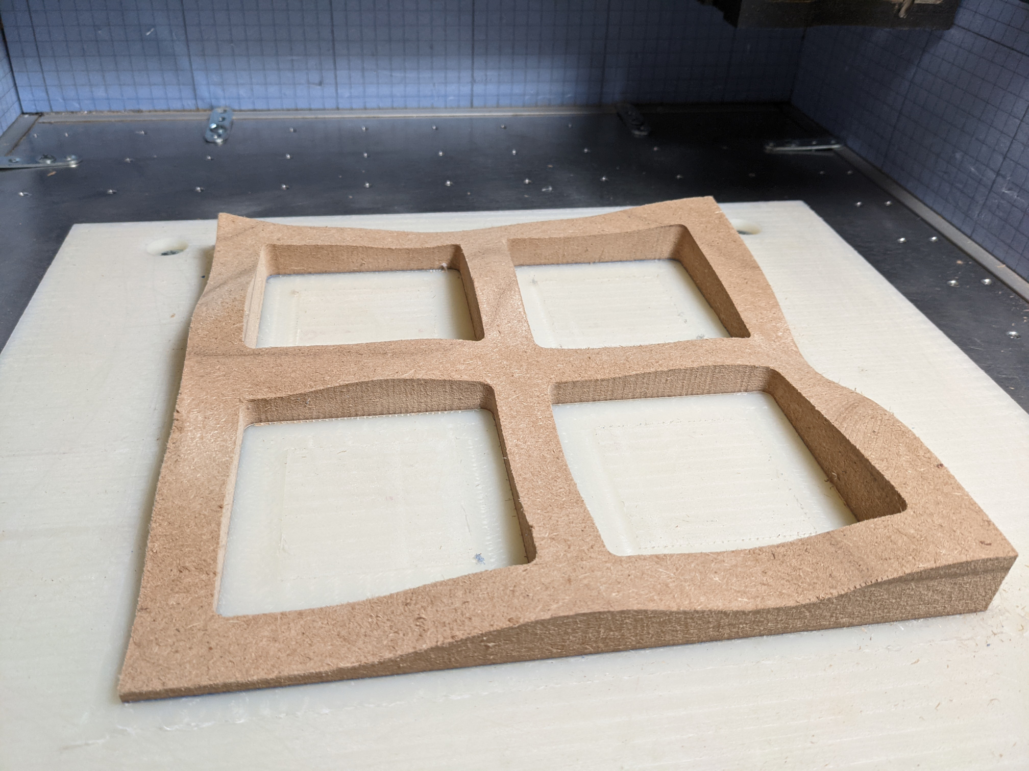
Something weird happened in that area:

Not sure what was wrong in the toolpath or cut, anyway I chose to ignore it to stay focused on the end game.

Then came the interesting part: cutting the other side. Which of course required a jig, so I first used the “Combine” tool to split a rectangular shape in half using the wavy object as the cutting tool:

The upper part is the jig that will support the piece for milling the underside:

I added pockets to later be able to “push” the piece from the jig (more on this below)

When flipped, it looks like this, it’s obviously a negative version of the wavy surface, and the remaining material should be more than enough support to hold the piece:

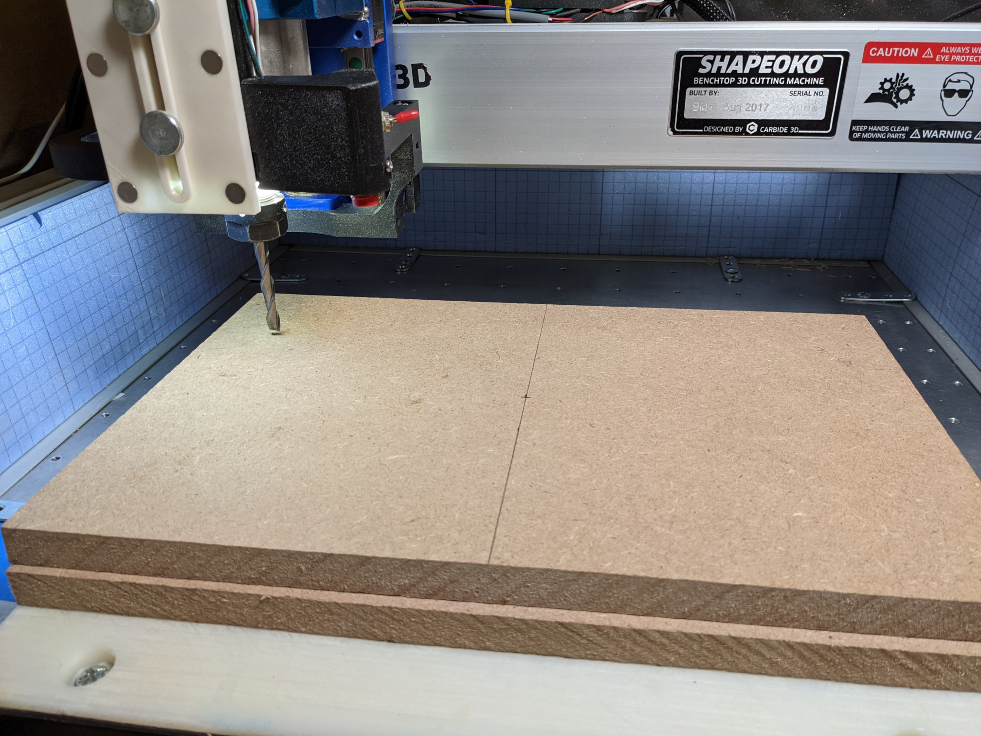
I glued two 3/4" sheets of MDF together to have enough thickness, and installed my long-LOC 8mm square endmill:

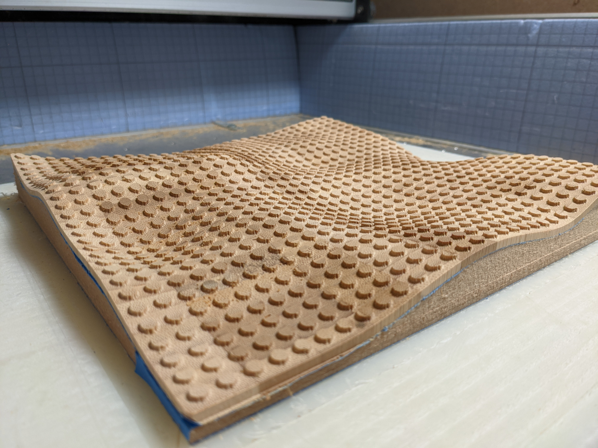
A bucket of dust later, I had this:

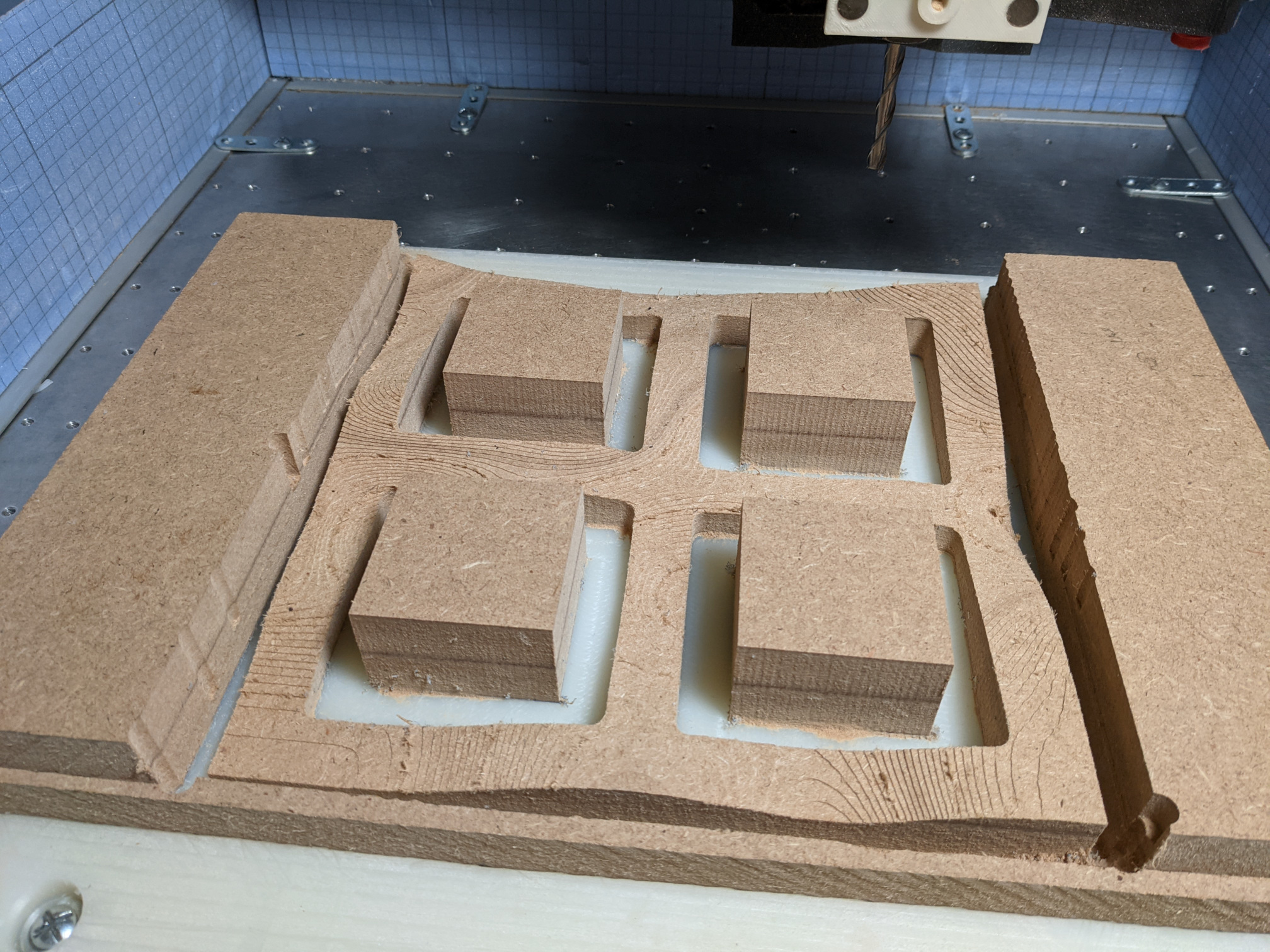
(side note: running an 8mm endmill fast through MDF with a sub-optimal dust collection, is a good way to end up with massive amounts of MDF dust all over the machine…sigh).

I then removed the outer and inner pieces out of the way,

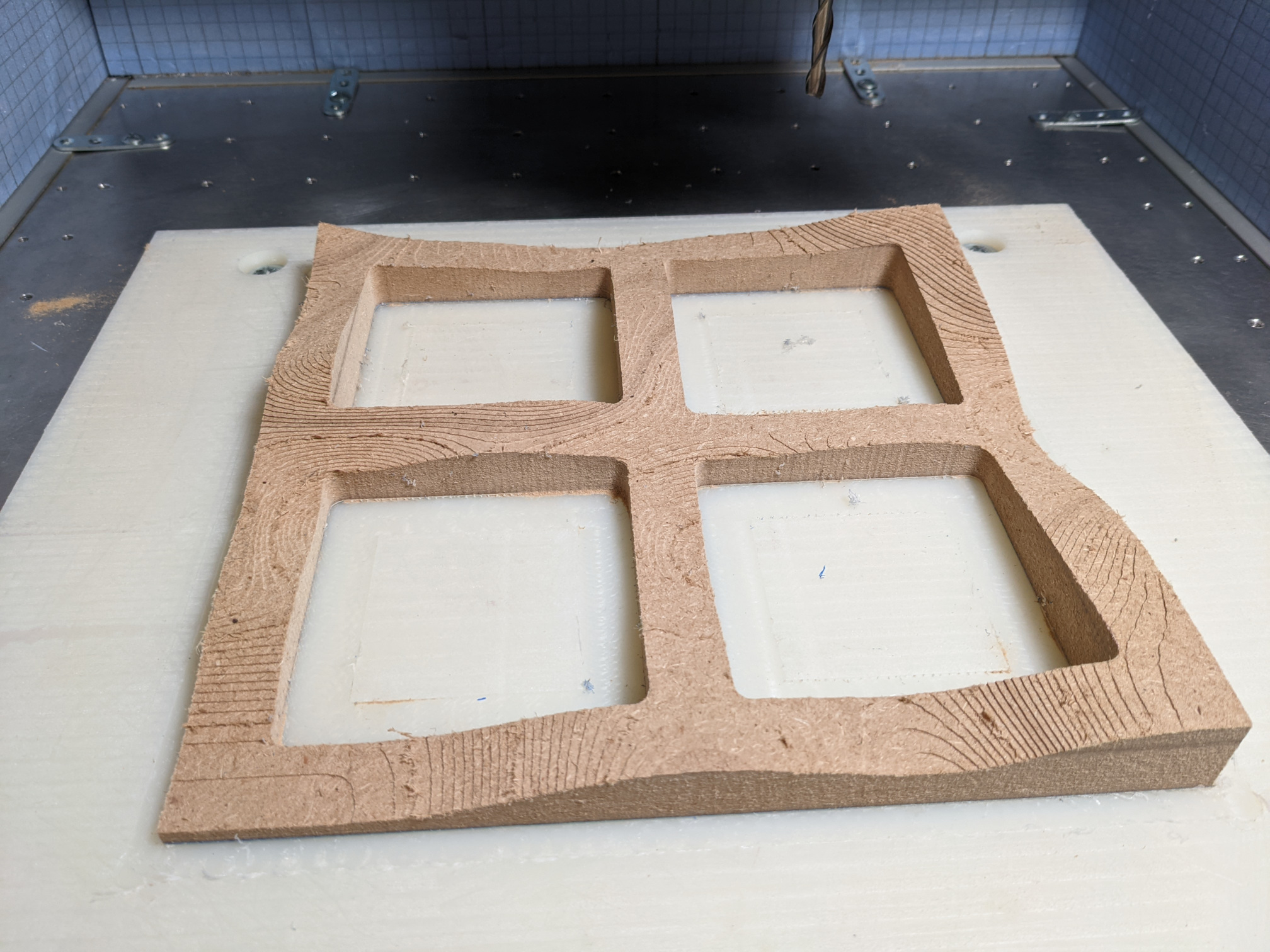
and ran the finishing pass for the MDF jig:

And then…tape & glue party time !

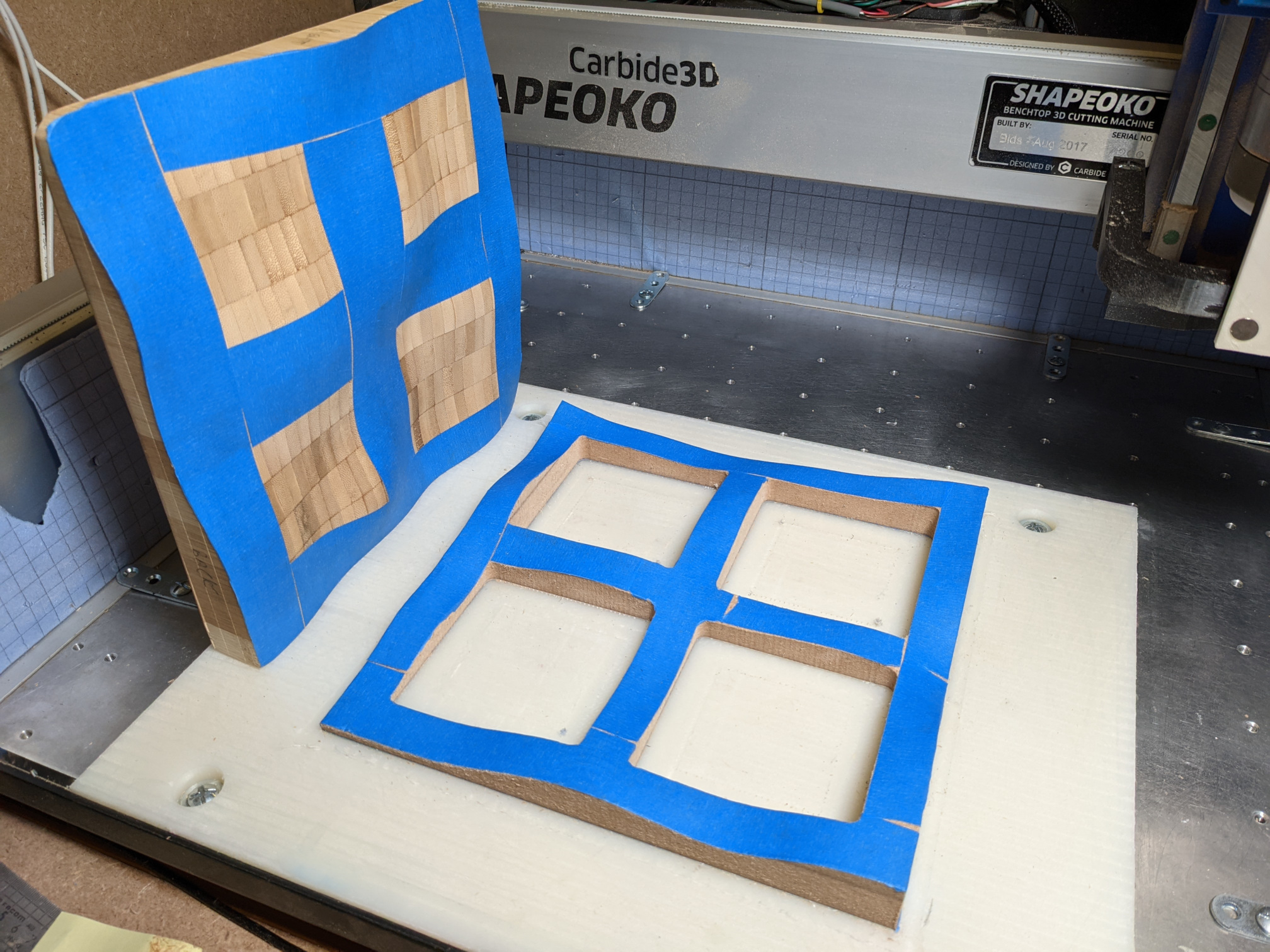
It’s a satisfying moment when the piece falls in place perfectly onto the jig:

Then I CAMed the other side of the wavy surface, by just creating a new stock setup with axis flipped

Ran that,

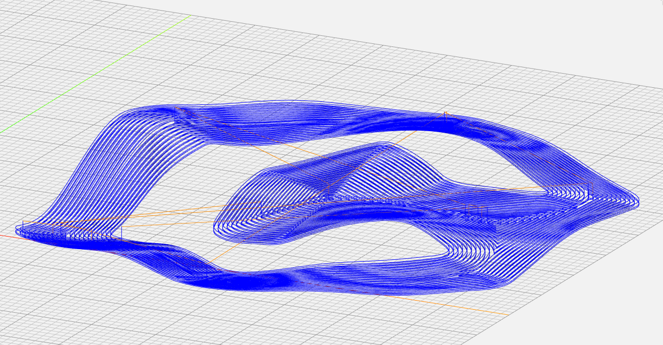
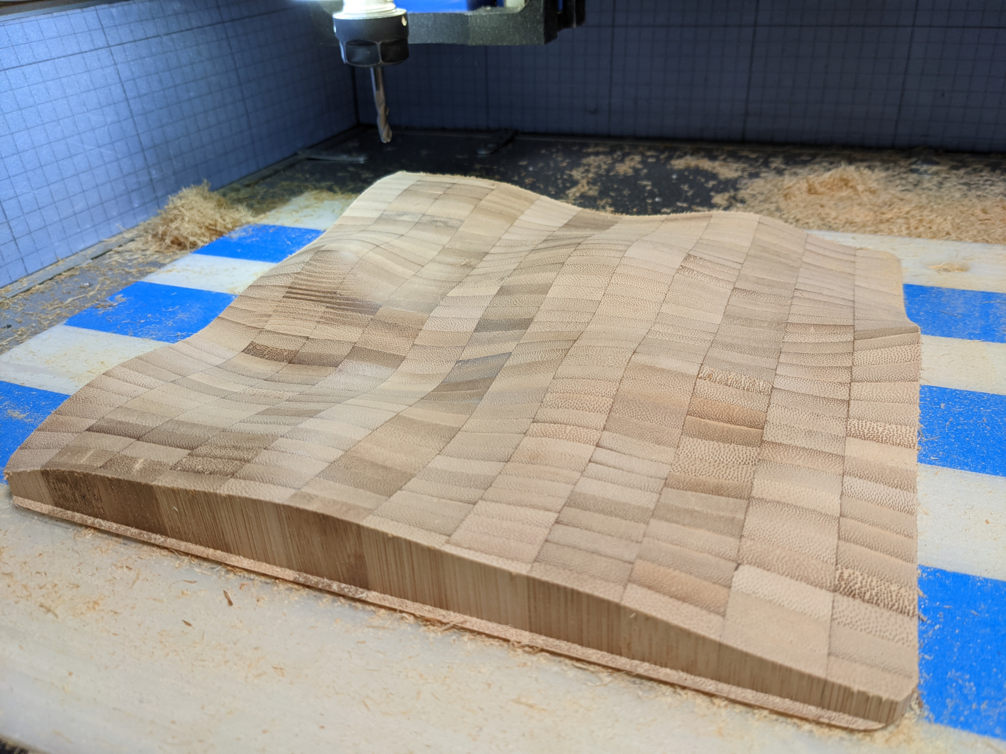
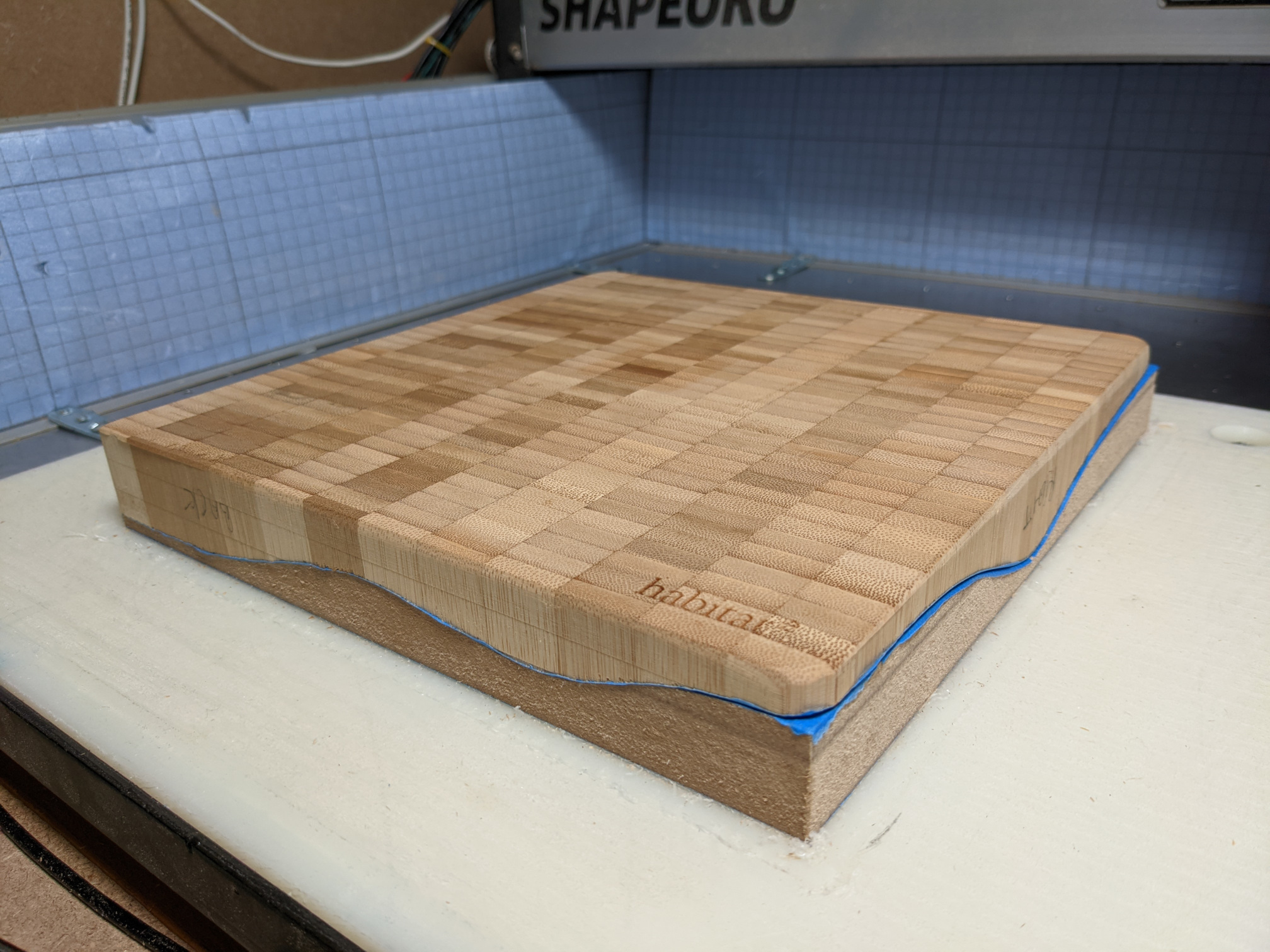
followed by the finishing toolpath for that side:

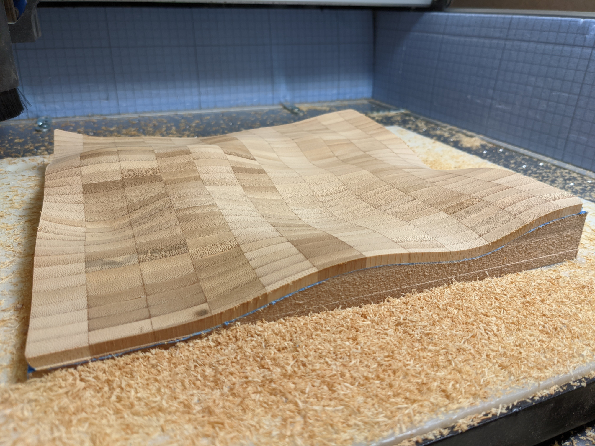
And…that’s where I am. NOW the question (for you guys),

  • do I just separate the piece from the jig, sand it, oil it, and call it done ?
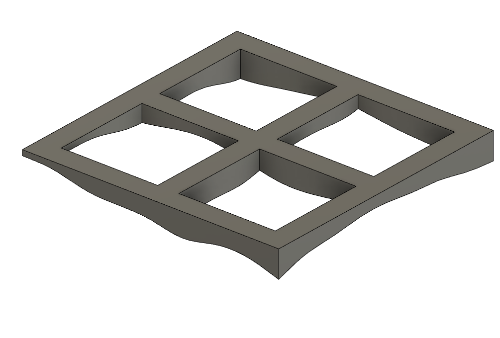
  • or do I keep it on the jig and carve something else in it ? I have this urge to mill hexagons to end up with grid-like wavy surface, but it may be too much and not look as good as I think it will. Or carve letters through.

Please let me know what you would do at this point ?

4 Likes

I think I voted with my spindle :slight_smile:

3 Likes

Ha, could be the opportunity to test your G-code overlay-modulation-whatchacallit tool indeed.
Since I did not start from an STL, I tried the following:

  • exported this to STL

  • Drew a “random” toolpath in CC, 3mm deep pocketing (my object is 5mm thick)

Pretty cool.

Of course since I did not follow the full workflow from an initial STL file, the height may not be quite right, I’ll have to quadruple-check my settings if I proceed with this.

Unless other folks come up with other ideas, I may just try this!

2 Likes

the only thing I can suggest is to make sure you take a small enough stepover on the CC side… (you’re effectively 3D carving the final, so pick a stepover consistent with that)

1 Like

I say use a couple more boards to make complimentary pieces to rebuild the original flat stock.

4 Likes

ohh interesting idea… tile the original gcode (ha!) and cut it out of other stock

Do it in two different woods and then plane the whole thing flat to expose the pattern :wink:

well that would take a tool that takes the gcode used to make a 3d cut, and then do the “inverse” cut to make it perfectly fit.

not sure that exists

These are looking really good now.

Have you considered making the standard ‘jewellery box’ type gift box with a rectangular inner milled out of laminated thicknesses of this solid bamboo but with the outside faces milled into these wavy patterns?

3 Likes

Pretty cool when the work piece was on the jig; it looked like a “melting” cutting board.

1 Like

Frame it.
Make a nice but contrasting frame, suspend the piece in the frame at the same angle it is to the worktable now. Finished frame, unfinished piece…

1 Like

And then we could call it “subtractive-reconstructive manufacturing”, which would be a nice word for “pointless” (or “art”) :slight_smile:

Come on, you know you want to implement it :wink:

Funny you should mention this, my wife keeps reminding me that I owe her a fancy CNCed jewelry box

I’ll name it the “Dali board” then :wink:

Ha. Interesting…very interesting. I was also thinking, maybe mill a stand that would put the piece just at the right height above “sea level”, and that would be small enough to be hidden (e.g. a single pillar in the center). And then that would give the illusion of a floating piece of wood.

I guess no one escapes their destiny. I’ll keep trying !

2 Likes

It looks like the surface of Mars. So embrace it, mill it with Lego knobs all over and let that be your base for the Lego community challenge.

Remember the old lego mats that had smooth surfaces for the roads. Well you can have a space rover on lego wheels (therefore it is ok that the knobs are not at the same height. And I’m sure there will be a place where you will have a 1x2 that is at the same height so you can put your Lego astronauts.

FYI - I’m expecting the space rover to be Lego Technics

1 Like

Don’t trigger me like that! It’s like the stars are aligning, and it’s the perfect usecase for using @fenrus G-code wrapping tool. The official Lego knob is 1.7mm high, and I have 5mm thickness, so that’s workable.

2 Likes

You never know what you will learn on a CNC forum…thanks for the heads-up, I need to step up my “English vulgar vernacular” game to not make a fool of myself then :wink:

2 Likes

You forgot to say “Pun Intended!” :smiley:

4 Likes

I figured I would take ZERO chances, and went with doing it in Fusion360 directly, which was incredibly easy (pattern of circles, extrude, offset -1.7mm from target surface, done)

I’m really tempted to give this a go. Now for some toolpathing…

1 Like

Curvy bricks to go with it?

1 Like

This is perfect timing–I was thinking of doing something very similar, but the idea would once I finish making the wavy piece, I then take it to the tablesaw and cut it up into say 25 square pieces, and put in a box as a puzzle.

1 Like

Well it turned out ok, I chose to use a 1/16" ballnose to carve it:

the [round things that I can’t name now as I am too afraid it will turn out to be more vulgar vernacular] would benefit from running another toolpath, the ballnose + parallel toolpath leaves obvious toolmarks, but for some reason I like it (and I will probably not push my luck, at this point I could mess it up real quick)

Next up, removing it from the jig without breaking it, i.e. something I will not do at 10.30pm, that will be for tomorrow.

9 Likes