I am a first time user of my Shapeoko 3 and I also new to Fusion 360, which I am using for designing the manufacture of aluminum panels for electronic devices. I’ll be using 0.08" (~2mm) 6061 alloy for my panels.
Yes, I have done a lot of searching though this forum looking for advice about feeds and speeds and have watch Winston’s video (https://youtu.be/RH4AXz_rtPo) several times. But I still have some doubts about whether my setup is going to be correct. I really want to prevent ruining an expensive end mill.
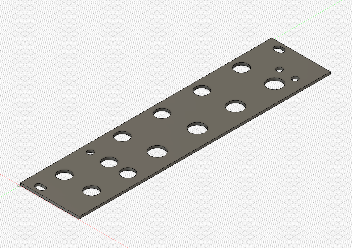
My panel has two 5mm by 3.2mm slots, three 3mm holes, nine 6.5mm holes and four 7.5 mm holes. I will be using a Nomad 274-Z 0.125 flat end mill for the larger holes and outside of the panel, and a 282-Z 2mm flat end mill for the smaller holes.
I set the feed and speed for what was recommended in the video, 10000 rpm and 508 mm/min. But what do I set the plunge rate too for when starting the holes. And where is that set in Fusion 360?
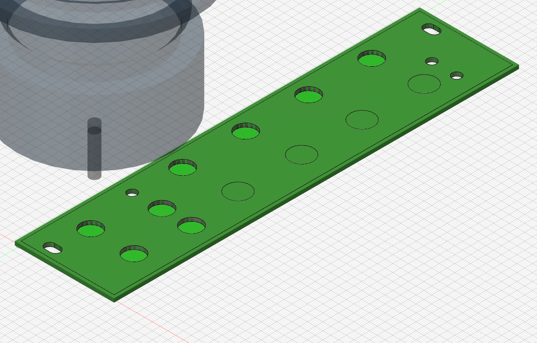
Also when I do the simulation for the larger holes it does not bore all the way through the material. Only when I set the Bottom Height to something less than 0 does it remove all the material. See attached picture.
I have also attached the .nc file produced by F360.
On the larger holes does your operation have “stock to leave” checked?
I would recommend against plunging, ramping down into the stock is generally less violent for the cutter and helps get the chips out more effectively.
I only see a boring operation in that nc file, what are you using for the larger holes? An adaptive clear followed by a contour works well for the larger holes and the slots.
I had more success with single flute cutters in Aluminium, but you’ve chosen a decent hard alloy which does machine. Air blast or suction to get the chips out of the way are table stakes for getting a decent result.
How are you planning to hold the piece? For this I’d suggest the Scotch Blue 2090 tape and superglue, works really well. Clean the piece first with Isopropanol (which is also great at getting tape goo off later).
EDIT - I realised it might not be obvious, it is quite common practice to run a ‘roughing’ cut first, using a strategy like an adaptive clear set to have, say 0.5mm stock to leave, then to come back and do ‘finishing’ passes at a much lighter cut, say, 0.25mm stepover to give a clean finish.
Thanks for reply. Now I realize that it takes more than a single operation to create the holes. I mistakenly thought that I needed to only choose the bore operation to make the hole.
I have a lot to learn.
Yes, I was going to use tape and super glue to hold the plate. All the cutters I will be using are single flute.
The bore op can be a good choice for the smaller holes, for the larger holes something else is likely to be better.
Figuring out which operations to use in what orders is really confusing when you first start using Fusion.
For the larger holes you have a few choices, they are basically;
Rough out the whole centre of the hole and then do a finishing pass around the edge to make it clean. This would be, say, an adaptive clearing with stock to leave followed by a 2D contour. This is probably best for your slots.
Run some sort of contour cut around the edge and leave the disk in the middle, which you can probably get away with on the glue & tape hold down method. You could still do a finishing pass by selecting the finishing passes & stepover options in the contour toolpath setup.
As your plate is only 2mm it shouldn’t be too hard to get a decent result.
I’d suggest trying out the cuts you plan to use on a test piece before doing the whole panel.
Like Nick says, the boring op works well for making small holes with, it’s the CNC version of drilling.
I messed it up a few times;
but after Vince, Nick and others pointed some things out I changed what I was doing to;
A 1 degree ramp angle (in a boring op I think it is depth per revolution)
A bit that was sufficiently smaller than the hole I was making, 3.125mm for 4.2mm hole was OK, 4mm bit for 4.2mm hole gave me trouble getting the chips out
Backing off the feed speed far enough based on that handy formula from Haas
It worked out OK.
As you’re only going through 2mm of material you shouldn’t have too much trouble with chip evacuation, these are not deep holes…
I’d suggest making sure your workholding allows you to cut through the bottom of the stock if necessary, i.e. don’t use a hard metal as the workholding base, use a plastic, a sheet of MDF or something like that.
I’d also suggest that you set your work co-ordinate system in the Fusion job setup to be the base of the workpiece, that is, the top of your workholding base. If you do this then it’s much easier to machine accurately to the bottom and not leave a skin you have to trim out.