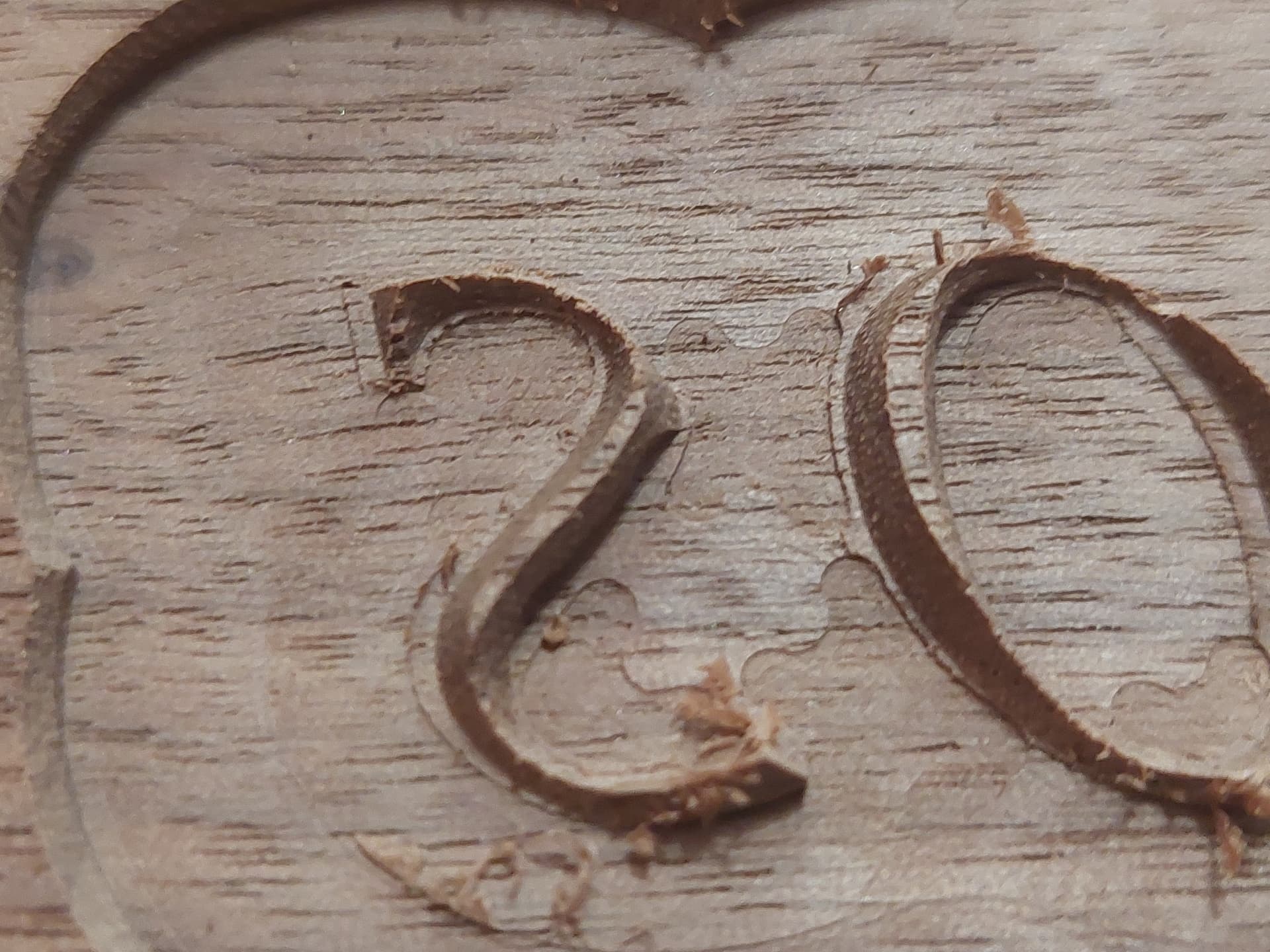
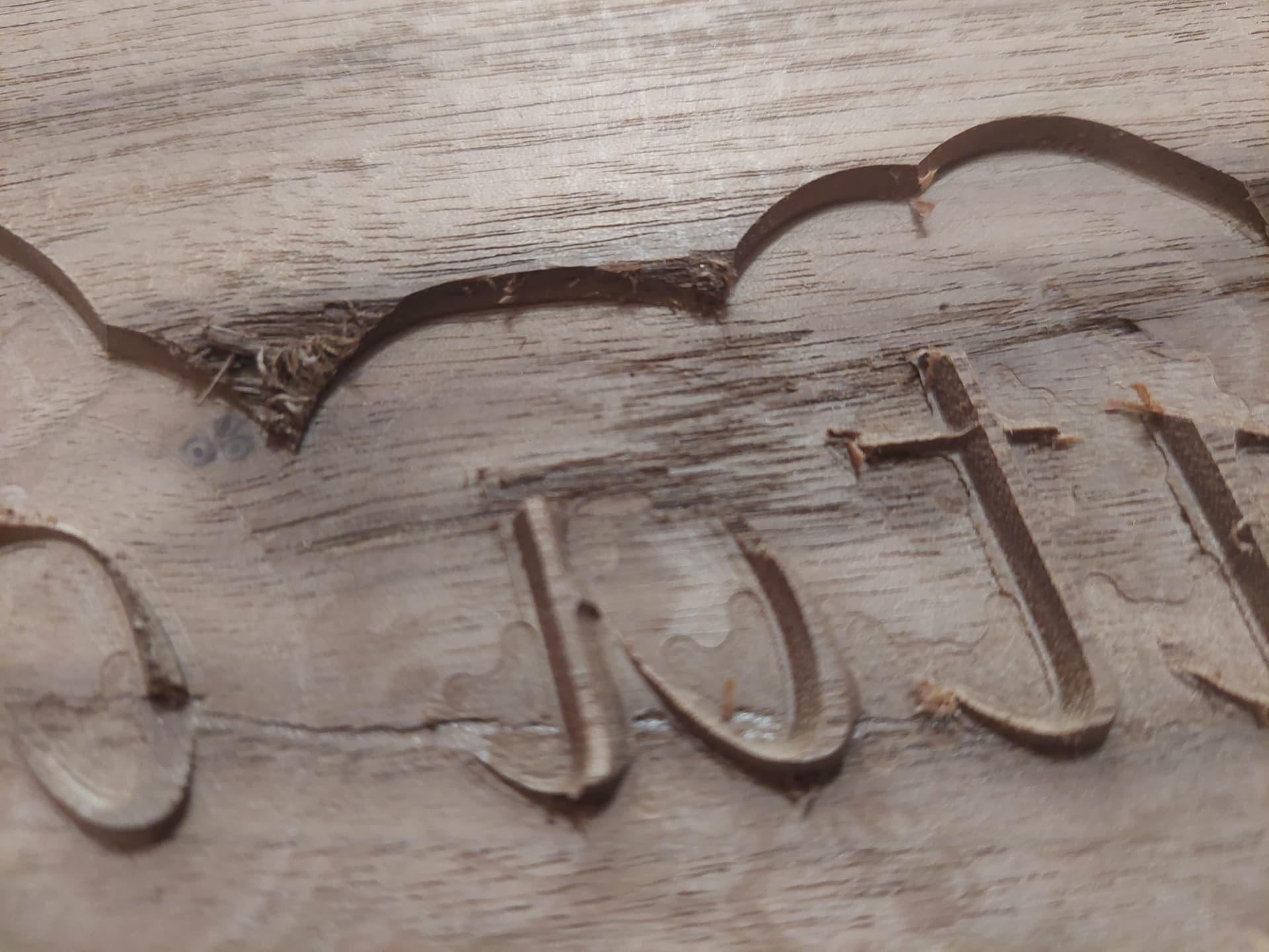
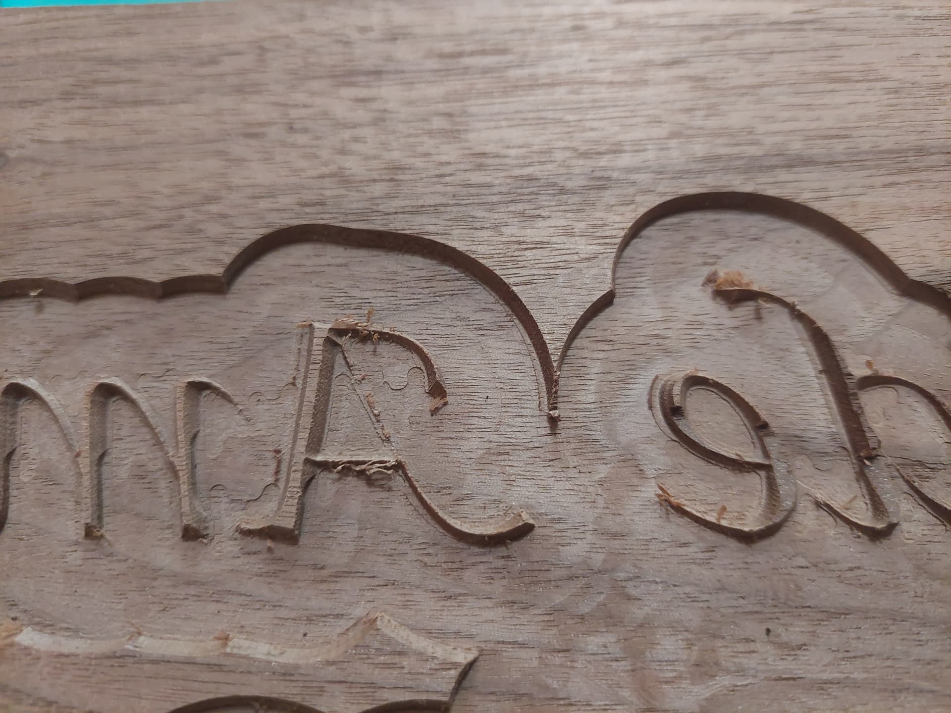
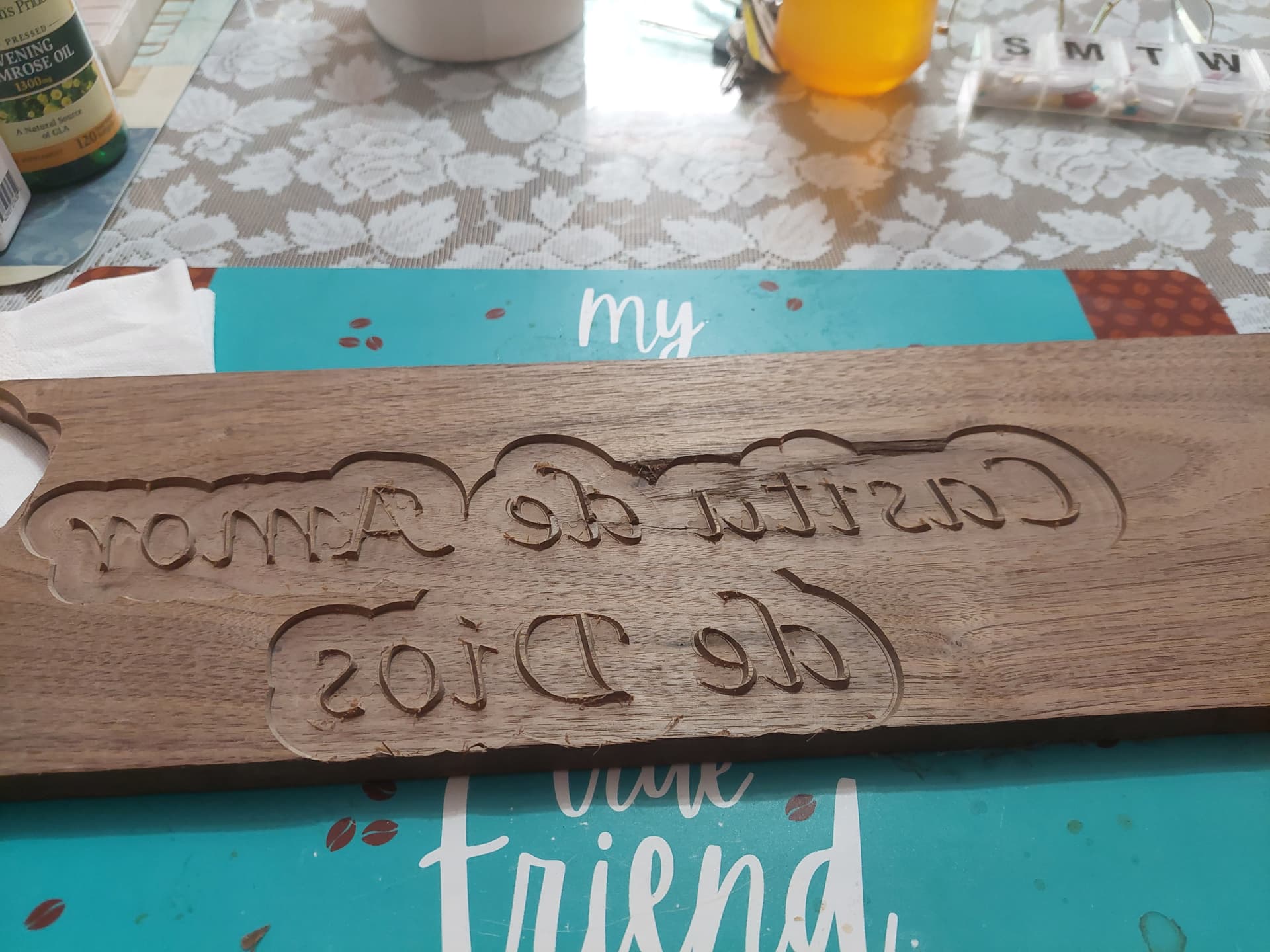
I have been struggling for 2 months now trying to get an inlay project to work and am at the point of about giving up on it. I have attached a picture of the male and female side as they appear in simulation. In reality the female side is wonderful, but the male side is a mess. The problem I am having is with the letters on the male side. They break off and chip beyond use. It seems to me that there are one of two cures: 1) the cutting of the male side has to be done in VERY fine increments (but I can’t figure out how to do that), or 2) start the same project over, discard the work I’ve already done and come up with a new font that will work.
The parameters I am working with: project size 14.875 Width, 12.8125 Height. Letters as seen, which probably need to be replaced, on the project: Lucidia Calligraphy with text height of 1.3
If anyone has a solution to item #1 above I’d love to hear about it.
If I am forced to solution #2 I am wondering if anyone who has done an inlay project with letters that have not chipped out on either male or female side I’d appreciate hear your recommendation, keeping in mind the limits as noted above.
If any of the source files would be of help I’d be happy to attach those if you ask for them.
This looks to either be a mechanical issue (check pulley set screws, belt tension, lubrication/cleanliness) or a feeds and speeds and depth per pass issue.
In particular, adjust the depth per pass so that the last pass is essentially a finishing pass, e.g., if wanting to cut 0.5" deep w/ a depth per pass of 0.125" (so that the machine makes 4 full depth passes) reduce the depth per pass to 0.124", so that the machine makes 4 essentially full depth passes, then a finishing pass of just 0.004"
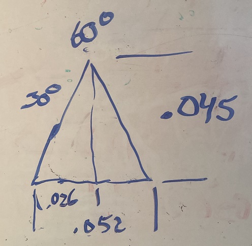
What about clicking the “Bold” box in the text tool? The smallest parts of your lettering (~0.035") would go to ~0.052". That may help a bit. Then if you can, limit your depth to less than 0.045 to leave a small flat on top of the letters. (with a 60° bit).
Seal / Finish the crap out of the top of your male before cutting it. This will bond the wood fibers together & help keep them from splitting off. Let the finish dry completely before cutting.
Will’s “Rough → finish” suggestion will help a lot as well.
I always cut the letters with the “v” bit before the clearance tool is used. That way the letters have more support.
Also I try and orientate the letters so that the letters are orientated with the long grain. You could try cutting the words/letters individually, instead of the way you are.
Will: before I make those changes let me ask a question if I may. With a start dept of .09 and a flat dept of .02 can you tell me what the router’s first move is when the program begins to run?
The pictures I sent you about this, the settings for the V bit were as follows: .05 depth per pass, .005 final pass step over, .05 clearance step pass over, 40 IPM feed rate, 20 IPM plung rate, 20,000 spindle speed. Knowing this would you please give me your recommended settings?
Could you glue up an end-grain board? Having the grain oriented vertically would completely change the way the wood wants to split, and would likely help preserve the fine details.
That was I that suggested Bold. Bold will make each letter a bit thicker. You would need to recut the female side to accommodate the new thicker male. The bold text completely encompasses the thinner plain text so you would just be making each letter a bit bigger.
Will: I tried setting the depth per pass to .01, but I can tell you that when I ran the program it made a cut much deeper than .01
I asked you about some my settings. I no longer use Carbide create and am now using Vectric. Do you think you could take a look at those settings I sent you and let me know what you would recommend?
Like you I first V carve and then clear. Since the V bit clears both the inner and outer portions of the clearance are I don’t know what difference the up or down cut would make since it never touches the portions that are breaking out. Nevertheless, I used a down cut.
The problem doesn’t seem to be w/ the machine or Carbide Motion though.
Vectric doesn’t pay me to support their product, they don’t provide me w/ a license, and I find their software cluttered, annoying, and confusing (I bought a license for one project and haven’t used it since).
Create a very simple test file in Carbide Create — make a test cut in a piece of scrap — if that doesn’t work, let us know and we will help troubleshoot that.