Backlash, Deflection and Vibration

Excellent work Liam.
Yes, this thread is a definitive bookmark, just like the belt tension dissertation.

3 Likes

Obviously I added this to the community map.

What resonated most (pun intended) with me :

  • the XXL is a different beast than my SO3 and I tend to forget that when discussing dimensional accuracy.
  • placing stock in corners of the work area is a simple way to minimize belt-related deflection
  • raising the stock as much as possible (limited by clearance under the X axis) is an easy way to reduce Z axis front/back deflection.
  • the comparison of values is fascinating, but the absolute values themselves continue to impress me (particularly the SO3 values) and match my experience of being able to produce very precise parts with the roughing+finishing approach

I can’t wait to watch episode 4 after your linear rail upgrade.

9 Likes

also makes me ponder a counter weight behind the Z axis…

1 Like

Folks have done a counterweight when running a machine on a vertical mount — it works, but doubles the mass the stepper motors have to move.

1 Like

hmm true. well it’s really about counter “torque” so mass times distance to move the center of gravity… so smaller weight but longer arm perhaps :slight_smile:

3 Likes

What about a constant force spring though instead of a counterweight? It wouldn’t add much mass.

@LiamN

Awesome white paper!!!

So, one question I have is how much deformation of the v-wheels is induced by just having the machine powered off in the home position? And how long would any deformation of the delrin wheels last (minutes, hours, days, etc.)? (Maybe it would be a good idea to un-mount the z-carriage if one knows they wouldn’t be using the machine for a few weeks…)

Would running a 'warm-up program help smooth out any v-wheel deformation before using the machine for a precision job?

Finally, is your recommendation to tension the v-wheels to ~7.5 newtons?

2 Likes

And, not particularly energy efficient, but it would be a solution for the x-axis v-wheel deformation to have an external motor with a pair of strings, one each looping through each left and right endplate and attaching to the respective left and right sides of the z-carriage, slowly pulling the carriage to the left until stop, then pulling to the right until stop, while the machine was powered down… Super slow, like 1mm per minute…

This is obviously overkill… I need to remember be happier with what I can do, I couldn’t do anything like this 10 years ago. And the law of diminishing returns always kicks in (definitely outpacing my operator abilities): It always seems to be the case that to attain the final 3% of accuracy will cost me more than I have spent so far…

1 Like

:wink:

Yep, I wonder if @Vince.Fab will do separate proven cut recipes for the SO3 and XXL?

Yes, the accuracy was better than I expected it to be. I thought initially that I was chasing a backlash of about 0.1mm as that was the additional clearance I was having to add to the CAM but this appears to have been a combination of my over-tensioning the V Wheels (one on my HDZ was tight even at full adjustment) and cutters that were under-sized either through being blunt or just cheap.

1 Like

Thanks, I’m glad people are finding it useful.

Whatever the plastic Carbide uses for the V Wheels seems to be pretty robust, my machine has sat for several weeks at a time and the lumpiness goes away in a few minutes after starting the machine moving.

I deliberately filmed that pull test where it was all lumpy after it had been stationary overnight in order to capture a visible example.

Thinking about it, I’d say that keeping the rails and wheels clean and free of crud build up is probably a more useful endeavour, foreign object debris doesn’t just revert to shape.

I didn’t find any sensible way to measure the tension on the V-Wheels and bear in mind that whenever you add V-Wheel tension you’re increasing axis rolling friction, making any lumpiness worse and increasing backlash.

Measuring the resulting drag is one way but you need to remove the belt on that axis to separate the belt and motor drag which means re-tensioning so that’s lots of work and potential belt / steps recalibration.

I’m going back to the ‘just tight enough that I can’t turn the lower V Wheel with one finger’ tension on mine as I’m happy to trade a bit of cutting speed for lower backlash in my finishing cut.

Is that a useful answer?

5 Likes

I would be very interested to see a comparison of this. I suspect there’s a trade-off to be had between the weight of the carriage and spindle ‘preloading’ the Z nod down to the bottom and giving a predictable Z height (at least for the HDZ and Z+) vs the other deflections that are made worse by that static torque loading around the X beam…

Yes, that is the more useful ‘rule of finger’ for tensioning…

(Footnote: The ~7.5 newtons was intended as the force to roll the entire carriage, so for each pair of v-wheels, but I think the method you just described would be a better guideline.)

3 Likes

@Vince.Fab provided a good demonstration and explanation of that in this excellent video. Apparently these types of machines are better suited to high feed machining (HFM) than high speed machining (HSM) - but also with high cutting speeds (SFMs). @spargeltarzan, maybe high SFM and HFM endmills with material optimized rake angles and edge radii would be the “cat’s meow” for these machines?

6 Likes

Yep,

It’s all consistent which is good. I’m sure I recognise that spreadsheet he used :wink:

Also interesting to see how close to the mark Millalyzer is on the cutting performance predictions.

Be interesting to see if the same speeds are possible on an XL or XXL with it’s larger deflections. I note he was using a Z+ for that which is a good vote for that as a non-wobbly Z axis.

4 Likes

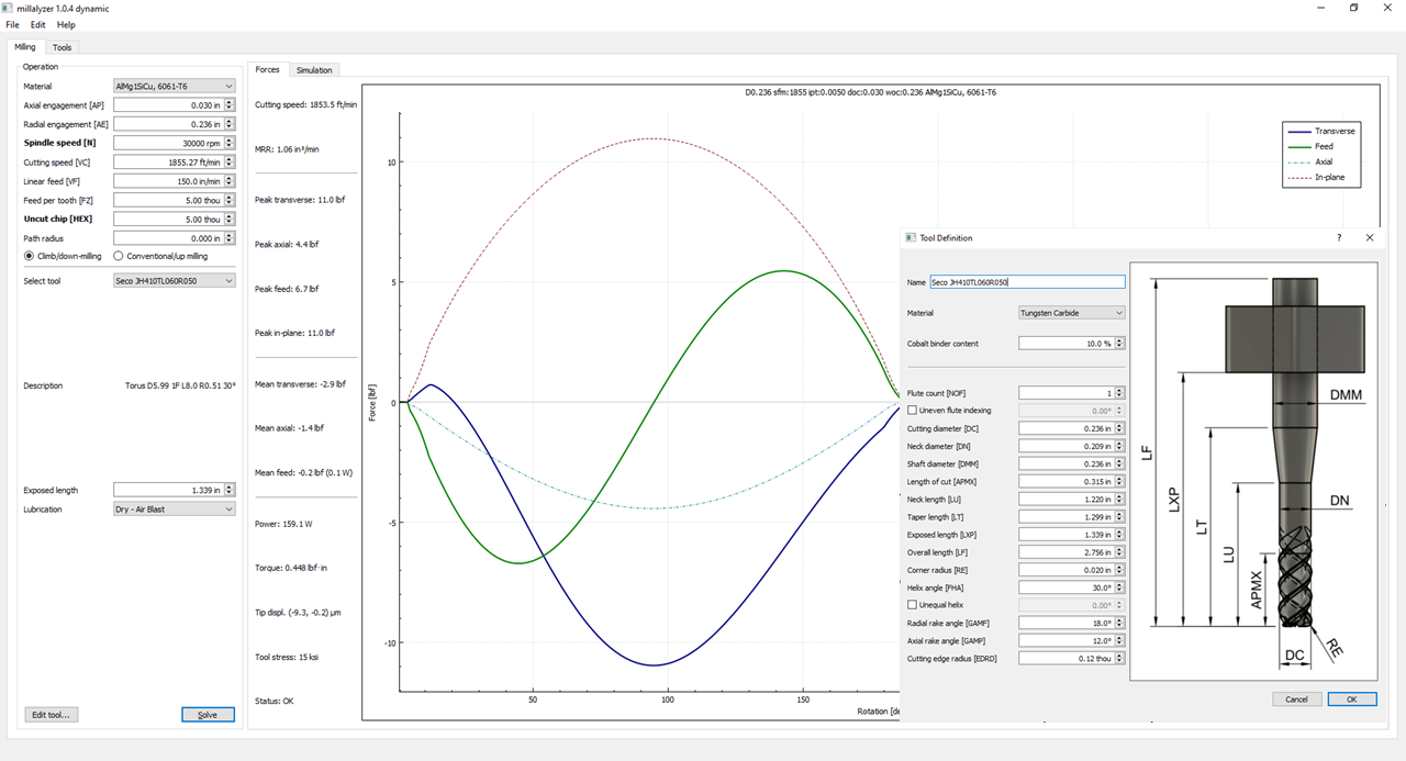
Not really. The VESC tool reports and logs input power, not output (cutting) power like Millalyzer and other calculators predict. Millalyzer’s estimates are also highly dependent on endmill geometry (rake angle, edge radius, helix angle, etc.)
Nice to see how little power is required to mill aluminum though!

2 Likes

Bah humbug, what am I going to use the other 2kW in my spindle for then? Heating? :cold_face:

4 Likes

Not so sure about high-feed endmills. Normally, those have a small lead angle (kappa or KAPR) of about 10° - in a way that makes them a V-bit with a very blunt 160 degree tip angle. As they are designed to cut with the face only (not the circumference), that limits the maximum axial engagement to very small values (for 10° lead, that is 8.8% diameter, or ap < 0.5 mm for a 6 mm tool). The lead angles gives you axial chip thinning, so you’d want to increase feed violently (theoretically by 5.8 times at 10°) to reach appropriate chip thickness values. At such high feeds, the steppers have lost most of their torque, so it might not be terribly practical, but certainly worth a test.

4 Likes

The Shapeoko Pro approach seems like a really reasonable solution to this problem. I wonder if anyone has measured how it performs. :question:

1 Like

Well, I kinda did as it happens…kinda. I wanted to do the industry standard “stand on the X rail” test I’ve seen someone do on another machine, but me on my Pro. But I wanted more science! So I stood my 185 lbs on the center of the X rail, which is the worst case scenario, and not the best case of standing near the sides like the other machine. I also added a dial indicator, because the difference between play and science is measuring. My Pro is on a kinda torsion box bench, so pretty sturdy.

My 185 lbs ass getting on the bed caused around 0.005" of defection between the bed and X rail.

This grown child getting on the X rail caused 0.015" defection between the X rail and bed.

3 Likes

This topic was automatically closed 30 days after the last reply. New replies are no longer allowed.