I have several bits that are less than 3mm for the cutting surface, a 2mm endmill, V carve bits, and some diamond drag bits.
When I use the BitZero to zero X+Y for the diamond drag bits, the zero locations are always off. The engraving point for X and Y zero is always off from the material. Is there a way to use the BitZero for these kind of bits? CM’s zeroing only shows 3mm as the smallest bit to select. There’s no option to select a bit that has what is basically a zero point diameter.
For your diamond drag bit they usually are spring loaded and have an outer shell that surrounds the diamond point. The BitZero on the X and Y is using the diameter of the bit to determine the X and Y positions. For instance a #201 is 1/4 inch so when the bit touches on the X and Y sides of the probe they know the diameter of the bit and translate the 1/8" radius to set X and Y. Maybe the diamond bit outer is touching the outside with the outter side of the bigger bit and setting the position wrong in relation to your diamond point. Did you set the diamond drag outer diameter in the custom bit setup or what ever part of the diamond drag bit is hitting the sides of the BitZero?
Jim, (reiterating what Guy said) XYZ zero is the same zero for your 2mm end mill or a vbit as it is with a 1/4" round rod. You don’t have to use your cutting bit to get those zero measurements.
You didn’t say whether you were using the BitZero V2 or the original one. The BitZero products have problems unless you hold them in place during the operation.
Hi Jim,
I have a BitZero V1 and BitSetter. I’m use a precision ground dowel pin for my set-up, setting X, Y, and Z zeros. After starting the part program I switch to the actual tool at the tool change prompt. For my diamond drag bits I have one of the vinyl protective sleeves trimmed to be the length of the uncompressed bit. This allows the BitSetter to make its measurement without compressing the spring. The catch being you need to feed hold the machine after the tool measurement to remove the sleeve (easy with a hardware button).
I was using the BitZero (V1) to probe only X and Y. The diamond bit is non-conductive so I manually set Z zero separately. I was placing the BitZero overlapping the material like you would with an X,Y,Z probe. That was the problem. I need to place the BitZero on the face of the material on the edge.
I don’t really understand why there is not an option to probe X,Y with the BitZero overlapping. It seems that would be more accurate than manually placing it on the edge of the material.
I think the new version of CM is a little confusing in this regard.
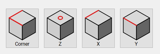
The menu/picture for what used to be called an “X,Y,Z” probe is labelled as a “corner probe for X and Y”… sounds like what @infinitemach wants,… but when you click that option it tells you will be doing the old-fashioned X, Y and Z probe.
So if your Z cannot be probed because it’s tip is non-conductive, then you’ve been led to the wrong place.
He hasn’t been led to the wrong place, he’s just using the wrong bit (cutter ) to perform the operation.
Perform the XYZ probe function with a precision dowel, then change your probe (use the change bit button!) to your spring-loaded bit (cutter ) and do the following or something similar to get the Z right for that bit.
I disagree. The “corner” probe in Carbide Motion is misleading and the image suggests it is X and Y only. You might easily go there and not expect a Z probe.
For the spring loaded bit I find it easy to just manually adjust the Z position. I simply lower the bit until it’s a little below the top of the material and set zero.
Well, that is not working for me. If I want to do an X or Y only probe and use the overlap method the zero positions are off by what appears to be the overlap thickness of the BitZero.
I downloaded the latest CM, mine was a version back.
Attached a 2mm endmill to the router, #282Z 2mm Single Flute ZrN
Placed BitZero V1 on corner of material, overlapping X & Y edges. I added a small shim on the back corner of the BitZero as the material I’m cutting is thin and this prevents the BitZero from rocking back. Made sure that BitZero is snug and in position.
Located bit to ready for probing.
Setup probe to do an X,Y&Z probe using 3mm endmill.
Start probe.
Probe finishes with no errors.
Examining the X,Y zero positions, X looks fine, center of the bit is right on the edge of the material. On the other hand the Y position is located into the material the width of the cutter.
Attached a 2mm endmill to the router, #282Z 2mm Single Flute ZrN
Setup probe to do an X,Y&Z probe using 3mm endmill.
If this isn’t a typo, then it is a probably a source of errors. The v1 BitZero can’t tell how thick the endmill is, so it will think it measured with a 3mm bit and set the offsets accordingly.
So when it touches the X it will think the centre of the spindle is 1.5mm to the right of the point of contact, and when it touches the Y it will think the centre of the spindle is 1.5mm south of the point of contact… when in both cases it is only 1mm away.
In addition to what @Gerry says, the shim means that the front corner of your material is not sitting flat on the underside of the BitZero. There’s no way it can determine an accurate zero from that. You’ve created an offset to the zero, which is what you reported earlier.