I’m trying to use dowel pins to join some parts together and to do that, I’m trying to nail down the right diameter to bore to get a tight fit on a 6mm h6 pin. I want a transition fit so that position is held under high loads perpendicular to the pin.
Such a fit requires that the walls of the hole are more or less parallel (well within ~12µm of parallel and a particular diameter).
However when I bore my holes, no matter what I do, I seem to get a taper. This is visible because when I try to put my dowel pin into my hole, it fits part of the way quite easily then it hits a point where it just stops and won’t go any further. It’s also clear because I can put my pin in through the hole on the top of the workpiece but not through the other side of the hole on the bottom of the workpiece.
I’ve tried various ways to fix this:
Boring twice (I’m using the bore toolpath in Fusion 360 which cuts with a helix pattern)
Adding a contour pass after the bore
Using a file to make sure there’s no debris in the hole
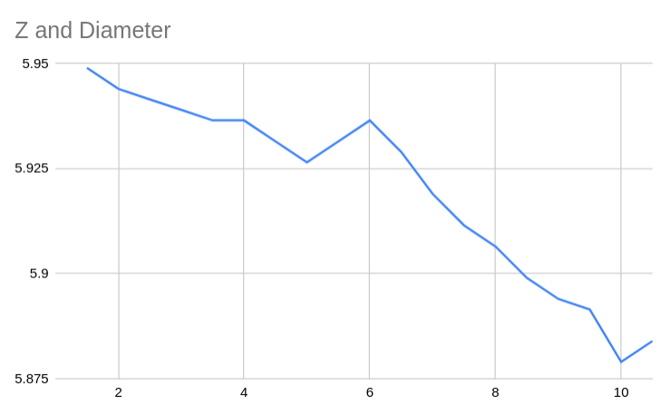
I was also able to quanitfy it. Using my mill + 3D probe as a poor man’s CMM, I can get the diameter of the hole at different depths:
X-axis is distance from the top of the hole, Y-axis is diameter of the hole.
So we can see that at the top of the hole, we have a diameter of 5.949mm. By the time we get to the bottom, we’ve got 5.879mm, a difference of 70µm, waaaay too much (note that I haven’t calibrated my probe, so the absolute numbers might be off, the relative numbers should be accurate though).
Anyone have any ideas?
I’ve ordered a reamer so worst case I can try that but it’d be kinda a pain.
The only things I can think of are just the general “how to decrease tool/machine deflection” tips:
Largest diameter tool realistically possible
Shortest flute length possible (stub tool with relieved shank would be best)
Shortest stickout possible
Do a spring pass
Limit your depth of cut
Raise your work piece as close to the spindle as you can
Make sure your chip clearing is very good
I assume you are doing this on your nomad? I am not sure you can achieve much better with this class of machine. I would love to be proven wrong. You are only seeing about 0.0014" deflection (sorry, I think in inches when numbers get super small) down a 10mm hole. I think your reamer may be your best bet.
I’m not 100% sure this is deflection though. Deflection is something that happens in an individual cut, right?
Like, if I took a 12mm deep, 0.1mm wide cut, I’d expect the material at the top of the cut to push the endmill away, causing deflection which would be visible in the bottom of the cut.
But in my case, I’m using a 0.3mm pitch helix to mill the hole. The material pushing against the endmill when it’s at the top of the hole should be basically the same as the material pushing the endmill when it’s at the bottom of the hole. There shouldn’t be any deflection here.
Plus, I’m doing spring passes, there should be negligible forces with those and negligible deflection.
Don’t get me wrong, deflection would look exactly like this, I just can’t wrap my head around how it’s happening in this situation, especially to this degree.
There must be a ‘standard’ correct answer to this, humans have been trying to machine things precisely for quite a few years. Candidates might include
What are the chances that your endmill has done more work at the bottom than the top and is actually slightly tapered?
As you go down the rabbit hole, if we consider the cutter being deflected into a curve then the closer to the collet (naively assuming the collet is perfectly rigid) we are the less tool deflection we are going to see, thus the top of the hole being larger radius
A reamer or broach gets away from both of these by passing through the hole and also pressing against the ‘opposite side’ of the hole as it passes through.
On our machines with smaller tools it does not take much to cause a little over 0.001" of deflection. As you bore deeper, the deflection will begin to stack ever so slightly because each pass will encounter just a tiny bit more material than the previous depth. Spring passes help with this but do not solve it. This is especially true because when you start rubbing a bit rather than cutting deflection will increase. Unless your tool is tapered, this is definitely deflection.
I suppose it could also have to do with machine tram. This is just a guess though. I still think deflection is more likely.
I think fairly unlikely, the endmill’s DLC coating is still visibly intact, so I don’t think there’s any chance that there’s 35µm of wear.
Hmm, so you’re basically suggesting that when I first cut the top of the hole, with the tip of the tool, there’s going to be more deflection, so it’s going to start a bit undersized, then as I bore down further into the hole, the top of the endmill, closer to the collet and subject to less deflection, is opening the undersized top up a bit more?
This is a testable hypothesis: I can bore say 3 instances of a hole: one 3mm deep, one 6mm deep, one 9mm deep and one full depth. If your theory holds, the deeper the hole, the wider the top.
It’s worth a go, to understand what behaviour you’re experiencing.
As Nick points out above, there’s also going to be an increasing amount of rubbing on the tool as it goes further down the hole so that’s going to also lead you toward a tapered hole.
It’s worth testing out but there’s probably a limit beyond which it is very difficult to improve for reasonable expense, and using a reamer is the economical and time saving solution. As said above, there has to be a reason they are still made.
Two methods I have used, lots of test cuts to get an exact oversize on the hole till the pin fits through the bottom properly, use a long enough pin to fit through the stock, so when it is flipped the pin sticks out through the top and is snug. MDF wont taper like metal, in my experience, so the pin into the spoilboard should not have the same issues. I have gotten perfect 2 sided carves with this method, if the pin holes are too big, use paper strips, an even amount on each pin to snug it centered.
I plunge with a single flute into MDF for perfect bottom pin holes.
Second method is to measure how far down the taper starts, do multiple depth cuts with .005 increments using the stock depth height adjustment to start where the taper occurs, and go wider in small increments on the way down.
I bought half inch stainless dowels which seemed much easier to cut, with less taper then the smaller holes.
Can also cut a hole and use a drill press to cut out the taper on it.
Okay, tried reaming. I used Yes Tool YSRL solid carbide TiAlN-coated reamers, one 6.00mm, one 5.99mm, both H7 tolerance. I bored the hole to 5.88mm using a 1/8" endmill, applied a little bit of cutting fluid (Blaser Vascomill 10), then reamed at 4200 RPM with 600mm/min feed rate.
The reaming took 1.2s per hole and was utterly painless. Whenever I have high axial loads from things like drilling or plunging I’m always a bit scared of screwing the machine up. I accidentally rapid drilled into stock once and killed my spindle bearings, necessitating a ~400€ repair which I’d like to avoid. There was none of that here. I didn’t even hear any sounds from machining.
And wow are the results nice. This is the first time I’ve been able to machine such a tight fit myself. The hole bored by the 6mm reamer is nearly frictionless despite being quite close (which you’d expect from h6/H7, a clearance fit) but still has enough play in the shaft that you can easily feel it, while the hole bored by the 5.99mm reamer has a tiny bit of friction and close to zero play. IIUC, H7 5.99mm is essentially K7 6mm, so this should be h6/K7, a light transition fit.
I measured the play in the dowel pin by fixing the stock, putting a DTI on the pin and then pushing it around a bit. At the tip of the dowel pin (~25mm from the base of the hole), there was ~40µm of play and at the bottom, I measured ~10µm.
I’m trying to drill these holes so that I can join some plates that will be responsible for keeping my X-axis ballscrew in place under load though, so I really want zero play. I might try a 5.98mm reamer but in theory that should result in something between N7 and R7, right on the very edge between transition and interference fit.
I did think of that but the thermal expansion/contraction of a hole this size isn’t a whole lot so I wasn’t sure it would work, especially since I only have a home freezer and oven, no blowtorch or anything to get serious heat (and don’t want to ruin the temper). Have you tried it with 6mm holes?
That’s just the example use-case which was a 12mm hole in carbon steel. Recommended surface speed for Aluminium is 80m/min, which with a 6mm tool is ~4200 RPM. More detailed feeds and speeds here (but in German or French).
I’ve used it to release bolts and shafts of about that size by heating the surrounding material, that’s usually with a gas torch though. Take a sample plate and try it.