I am unfamiliar with ratings of the carriages, the amount of weight they can hold, etc, etc. I was thinking of some way to use them on the Y (and eventually X) without having to use an end plate on the X.
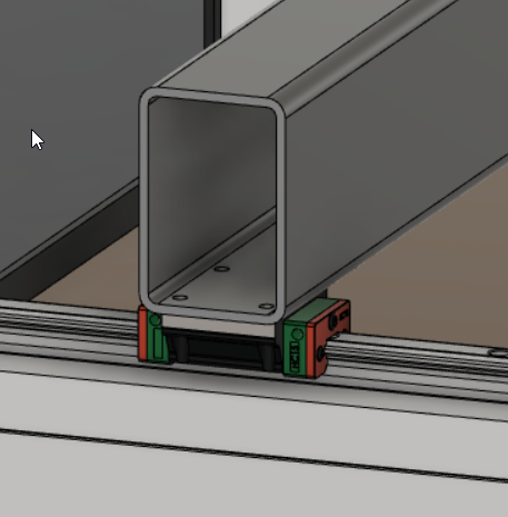
This would replace the X rail with a piece of 2"x3"x11ga steel square tubing. Not sure if the tubing is square enough and if I’d need to have at least 2 surfaces faced to ensure squareness (is that big bucks to have a local shop do that?)
This is using HGR15 rails and a single block on each side. If you hung an HDZ and a 2.2kw spindle, is that going to be too much weight for a single block?
Additionally, recommendations for attaching carriages to the back of the HDZ if one is to use them there? I’m thinking front mount the rails. Depending on how far apart from each other and the radius of the rectangular tube, might have to go to a 2"x3.5" tube.
There are quite a few suppliers of aluminium extrusion rail who supply them flat and square for this type of use, might save you some time and effort dealing with the steel.
There’s no problem with Aluminium, just use a slightly greater wall thickness than steel. If you want to stabilise the machine then short of 1/2 tonne of castings you’re probably better off using a composite with another material with a different damping coefficient to fill the extrusion.
The big question is, where are you going to move the belts / ballscrews to if the rail hangs over the Y rails?
I would just copy what Dan did here. He already did all the heavy lifting. The cost of the extra cars is so tiny in comparison to the design time. Plus as Liam said, the drivetrain is already figured out.
Thanks for the feedback. Yes, I think I’ll probably do what Dan did.
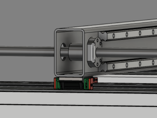
To answer LiamN’s question, I was going to do something more like:
It was more about keeping it simpler. It isn’t a complete design at all, just didn’t want to go too much down the path if one carriage wasn’t enough.
@LiamN Can you recommend any in the US? I’ll try googling. I probably won’t pursue this and implement what Dan did (been reviewing that this morning) but as learning exercise in design and CAD I might.
Sorry, I don’t know about suppliers in the US, here’s a thread with some links to the sort of engineering extrusion you might want though.
Also, those single rail carriages are likely to be a source of trouble, there’s a large torque waiting to be applied from the Z carriage via the X beam to those which will be hard to react over that small baseline and will at best result in those carriages easily binding up when your Y motors try to move the X gantry under load. A chunk of 10mm Alu tooling plate under the X gantry to spread that force out over a longer baseline is where most people go, much like the Shapeoko’s Y gantry plates.
I should add, if you’d like to read through the record of some people going through the design process and being guided through the common learning process by other forum members, this section of mycncuk is worth an evening (or two).
This sticky thread has some excellent basic “do NOT do this” hints, which certain machines coming to market this fall clearly failed to read (not C3D machines).