I have a crappy Rigid trim router that I can do that with. The problem is trying to hold them in alignment while I do this.
What?
You don’t think a blob of plasticine will do it?
@gmack found a very high speed rated coupler a couple of weeks ago.

Between just holding the routers still and keeping the shaft in perfect alignment at 10k RPM I think it will be difficult.
Wouldn’t the current waveform look the same running either sensorless or sensored?
Yes it would.
Hooking it up to the Oscilloscope is to verify that the current waveform is doing what the ODrive developer thinks is going on which is that the current waveform looks like a sawtooth from the Back EMF instead of a sinewave. So basically the ODrive is expecting the current waveform will be heading down at some point in the cycle period and instead it is continuing to rise. This causes the ODrive to think something is wrong so it throws an unstable current error and stops the motor.
In sensorless mode it appears to be factoring in the Back EMF into the waveform so this does not seem to trigger this unstable current error.
Sounds like a software/firmware problem to me!
It is:
No clue when or if they will get to this. It requires their development staff to basically have a motor that is doing this on a test bench and several days worth of time to get the code right.
Maybe they (and VESC) are using drivers that aren’t well suited for Halls sensors and/or are adding unnecessary complexity (like PID or FO control).
The ODrive works with Hall Sensors just fine. It is however using FOC.
Honestly if you could find a ESC that properly supports this motor (voltage, kV rating, current handling, etc) and just used a simple Arduino to PID control the speed it would work great. The problem I ran into was finding such an ESC. Everything out capable of handling the kV rating could not handle the voltage. Everything that could handle the voltage could not handle the kV. That is why I went with the VESC and now the ODrive.
FOC can’t be disabled to just use simple Hall sensor commutation, as is likely done in the router OEM controllers?
Ran some back to back Modkita (VESC) with a 1.5kw 110v in 6061 on the upgraded Nomad. Hands down the Modkita wins with MRR, you just can’t beat the rpm and associated machine forces. Oh… forgot to record the log file but cut was up in the high 200 watts.
Mod - 0.8 cubes @ 30krpm, top speed due to vibration with unbalanced tool. Will try a Datron 4-1 today and hoping for 1.2 cubes.
1.5kw 24krpm - 0.65 @ 24krpm max. Both axial and radial docs were adjusted and maxed out
Also out of left field. What would you guys think about adding a small flywheel? Something to just smooth everything out and damped things out a bit. Maybe a viscous dampener…
1 Like
And then, maybe a clutch, and some cylinders, maybe a turbo? I can see where this is going ![]()
4 Likes
…
Ran max in duty cycle mode, max load ipm, lets not get into docs please. Gotta look over the log more but its impressive. With this power the Nomad is rigidity limited and it should rip on a well setup Shapeoko.
So…how much more voltage you think it can take?..
@LiamN its shown to be plenty powerful already, the next step is making it smooth. A little weight wouldn’t hurt, it already spins up ridiculously fast.
Yep, and the electronics aren’t going to be able to respond at the sort of frequencies seen when the cutter hits material.
What sort of tooling would be required to make, fit and balance a flywheel for these kinds of RPMs?
1 Like
Honestly was debating on trying to see if one of the smaller turbo manufacturers might take on the challenge to dynamically balance the shaft/nut assembly.
On my unit without a fan, you’d have to press off the lower bearing, press on a fly wheel and then replace the bearing. I’m guessing it wouldn’t be too hard if you had access to a lathe.
This is probably the area where the inefficient squirrel cage VFD controlled motors have the advantage as they inherently adjust motor torque current with their mechanical slip angle.
BLDC motors generally have less mass on their stators. They just have permanent magnets and not stator coils. This makes them more efficient but it also means less mass spinning so a small flywheel might not hurt. Definitely get it balanced though. Tuning the PID controller though should lessen the impact of the this.
1 Like
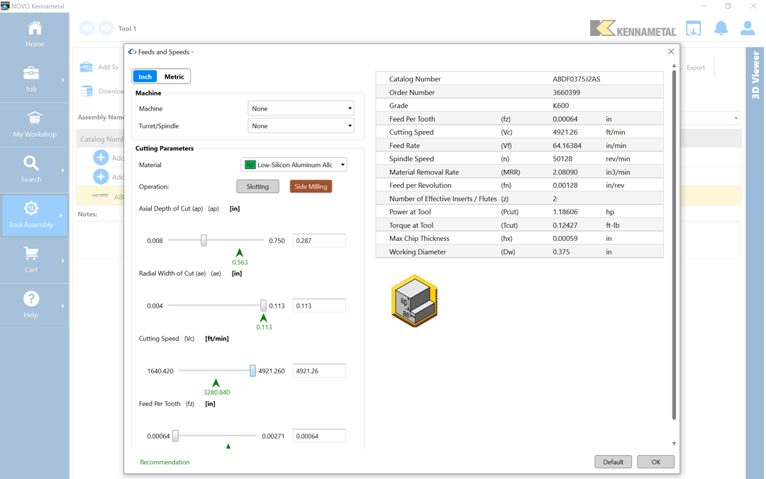
A two flute endmill at the same DOC would halve the cutting force per flute. Increasing the endmill diameter would proportionately decrease force for the same MRR. Here’s a 3/8" 2 flute endmill that could do both.

Here’s how it could be used in a manner consistent with the manufacturer’s speeds and feeds.

Since that series of endmills apparently want at least a 0.00059" maximum chip thickness and a 0.113 WOC, the DOC was increased to 0.287" to provide about 4 lbf at the recommended 33418 RPM, as shown below.

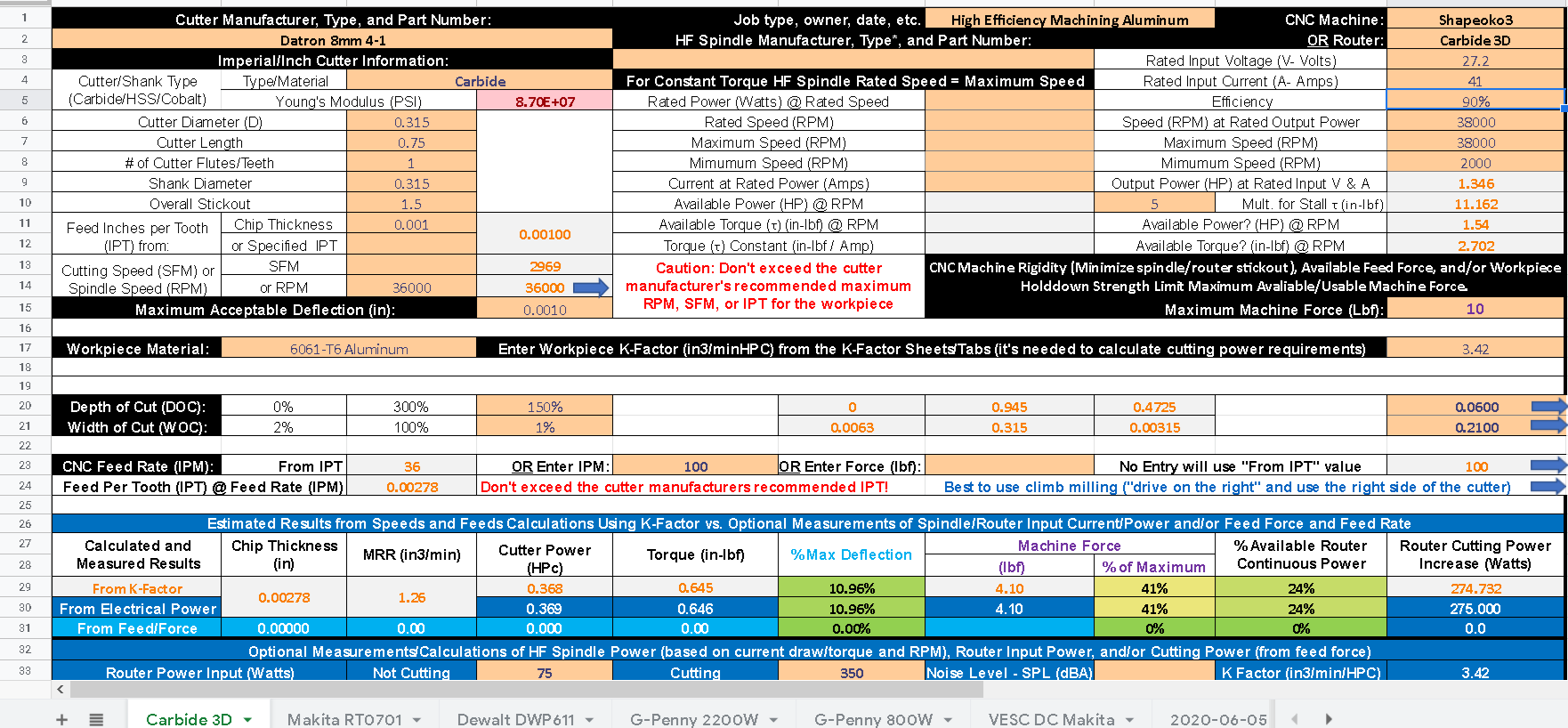
That’s only a little higher MMR than your single flute 8mm endmill for the same cutting force (shown below)

The Datron endmill is only rated for 34,000 RPM, but the Kennametal is rated for 50,000 RPM. That would give you a MMR of 2 cubic inches per minute without increasing forces (if you could run it that fast and had sufficient power/cooling.)
2 Likes