The windings of the motor have very low resistance and fairly low inductance. For instance my motor has 0.03 ohms of resistance and 8.4uH of inductance. If you were to apply 27V DC directly to those windings 900A of current would try to flow through them (this ignores the inductance because it is DC not AC). The power supply would fry long before this even happened. Instead the VESC or ODrive turns the 27V DC into an AC voltage using PWM. The AC voltage the motor sees is probably around 2V. Now without knowing for sure what the AC frequency is from the VESC or ODrive I cannot really calculate the over all impedance from the windings inductance winding resistance but it is fairly low. I would guess around 0.05 ohm but honestly I am pulling that out of my ass. 2V / 0.05ohm = 40A.
What you really want to make sure is that the power being fed to the motor is less than the power coming from the power supply.
Also the reason for running the VESC or the ODrive at a higher voltage is so you can deliver more power to them at the same current.
Is so the drive’s output voltage can exceed the motor’s back EMF (which is equal to speed / Kv) and IR losses to drive the required amount of current into the windings.
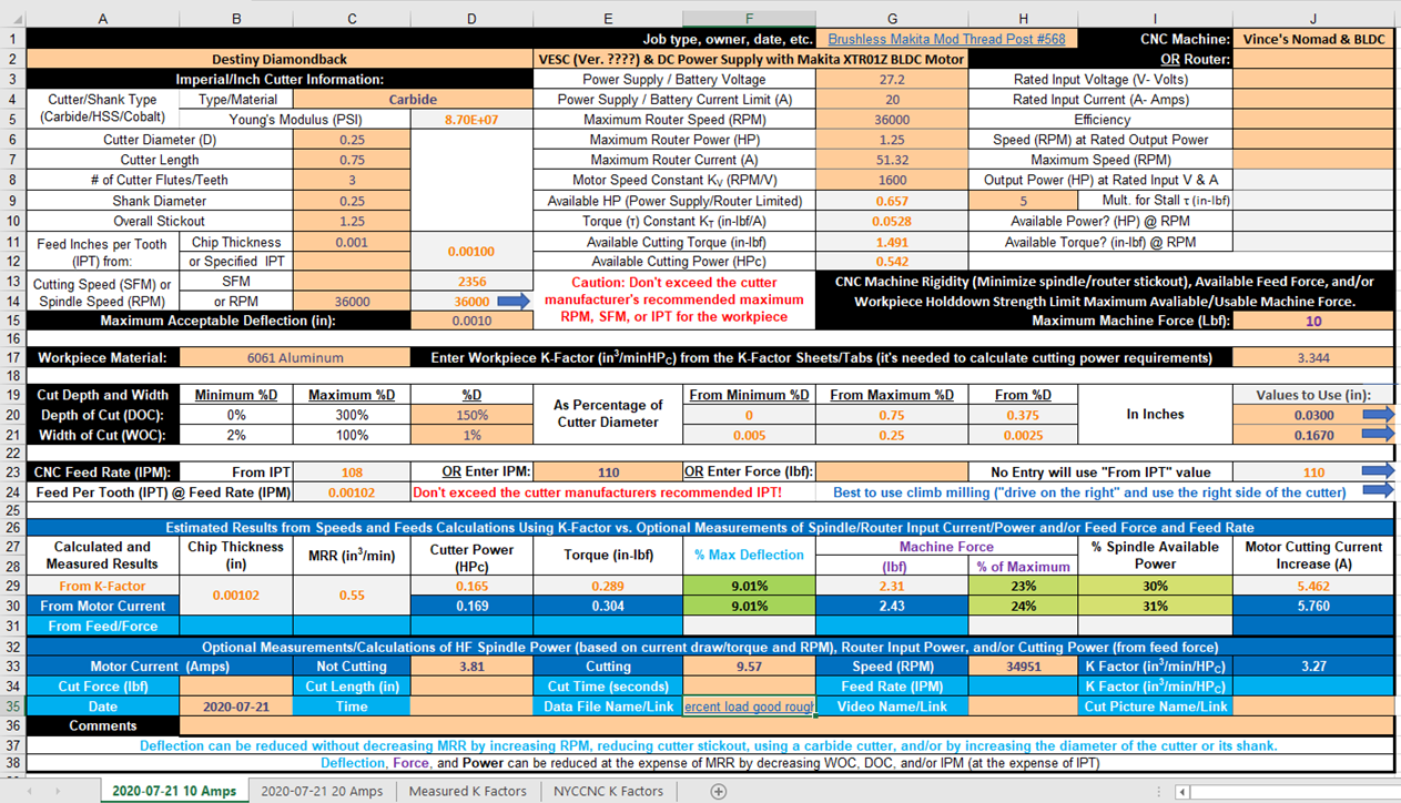
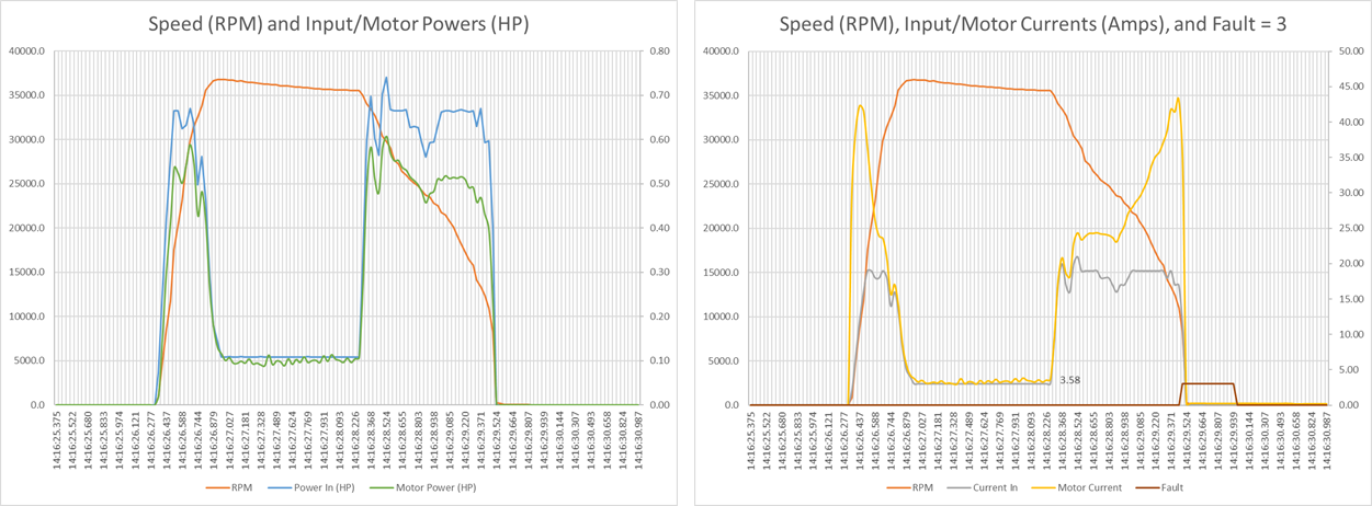
I used your workbook and maxed out the spindle power on a 20 amp power supply this morning in 6061. Your spindle inputs are correct and I’ll post the videos and csv files soon.
Ran 84% spindle load without issue and speed control mode kept me within 175 rpm of target, pretty surprising.
At 103% load the VESC faulted out.
So you were definitely right on the power supply. Question now is what to get now? Go for a 24v 1000w unit or try bumping the voltage?
On the PSU, the VESC should be relatively happy lowering the effective voltage by PWM chopping so more Volts should result in less Amps for any given load, the upper bound would be sensibly set by how hard you think the motor can be driven without turning into a puddle.
Given how hard you are driving the motor now it might be worth putting some stabliser capacitors in across the power rails to help avoid any short transient voltage kickback to the PSU causing that to overvolt, trip and overvolt the VESC when it loses the PSU but not the motor.
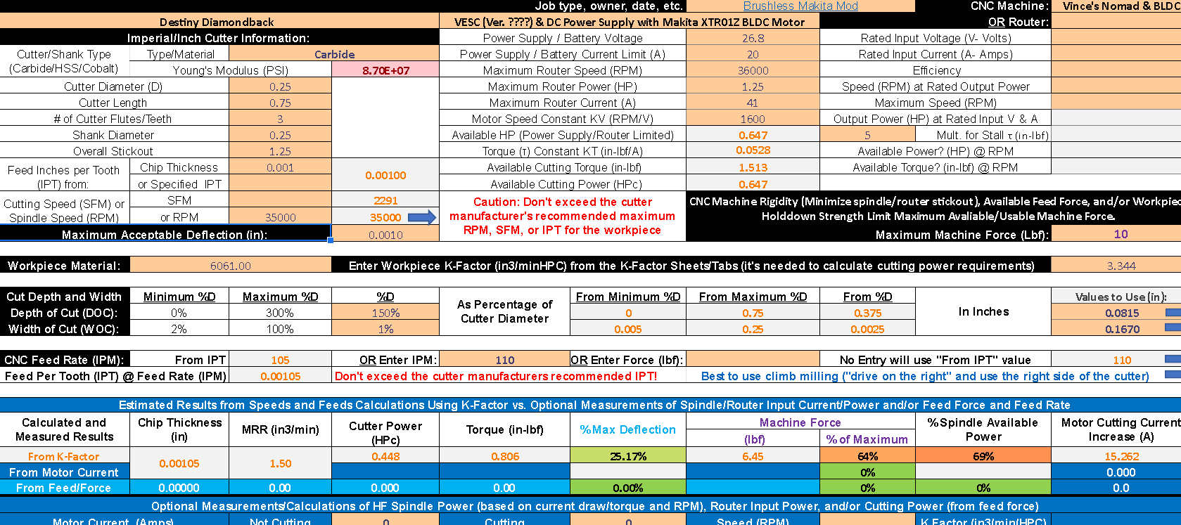
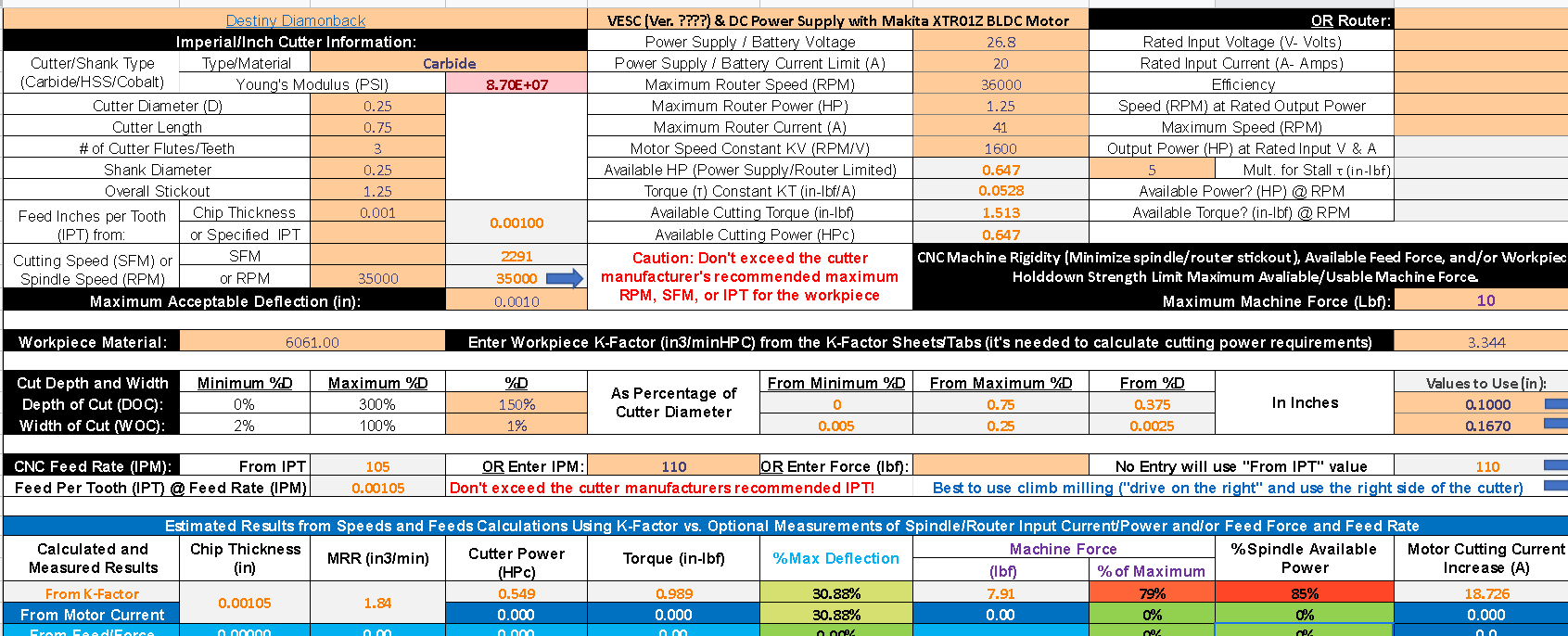
Those percentages were off from before, my apologies. I went through everything again and here are the clips/data. This is one of those times a fault feedhold would have helped. The end mill had a chamfer edge and was not harmed.
Axial depth of cut was 0.0815" on the first, 0.100" on the second.
I haven’t figured out how to read which faults in the log yet, just know they happened. The max current is set to around 45 on this one so that sounds right.
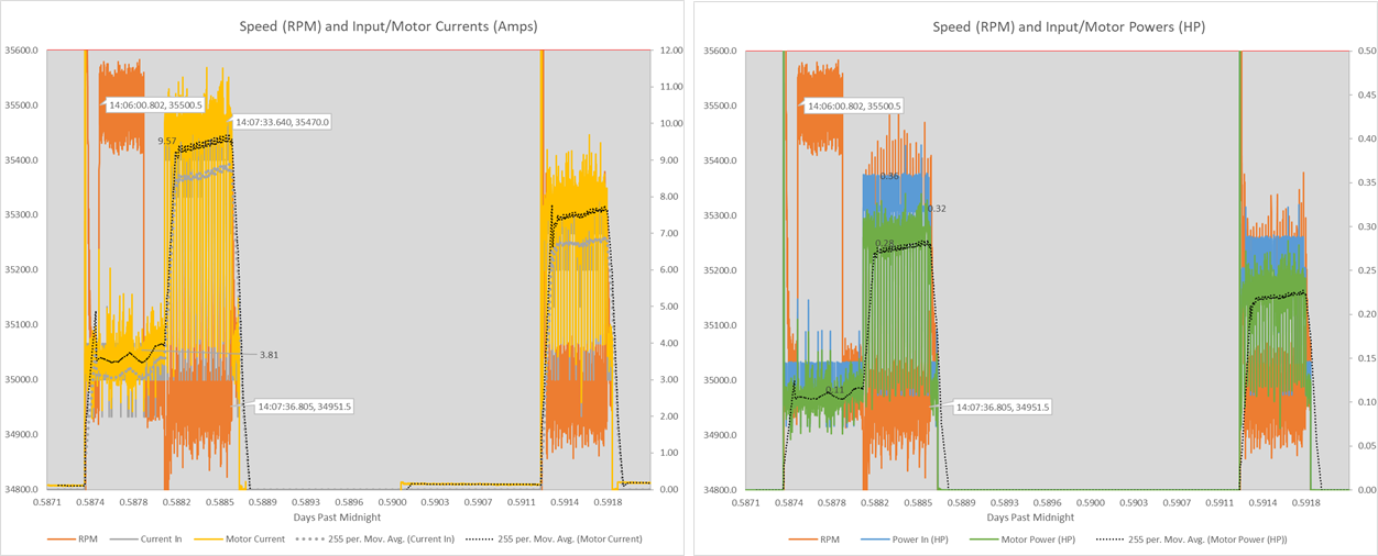
Then, since the motor current on first cut was 10 Amps, it should have only increased to (0.1 / 0.0815) * 10 = 12.3 Amps rather than the more 20 Amps on the second cut. Your video also appears to show that there is much more than a 23% difference in the depths of cut.
Yeah I noticed that too so maybe it requires a better test. A gradual stepped cut in one op for better data. I gotta start making real parts though lol.
So the last few things I have been trying to mill using Fusion 360 have resulted in smoking and charred red oak. I thought it might be that I was calculating the RPM info with the ODrive wrong so I bought a laser tachometer to make sure.
… Nope …
RPM is spot on. My feeds and speeds in Fusion 360 are just wrong. Good news though is I know that my RPM to Ve conversion is right.
Today I was cutting some hard maple, fairly thin and fragile workpiece so I was being gentle with it, contour toolpath cutting the full width of the cutter in a slot;
6.35mm endmill similar to carbide 201
RPM 22,000
Cutting feedrate 1200 mm / min
3mm DoC
Roughing passes;
stepover 3mm
1 stepover
(that’s to open up the slot for chip clearance as it goes deeper)
I’d push a bigger DoC if the workpiece wasn’t being cut up into fragile little bits.
Came back with a compression cutter (6.35mm) to clean up
RPM 22,000
900mm / min
2 finishing passes
0.25mm per pass
10mm DoC (whole workpiece)