It did heat up quite a bit but even the stock controller would do that. Keep in mind I haven’t put sustained constant loads on the spindle yet. More power has to equal more heat right. Its going to need some type of active cooling imo.
Also you can attach a temp sensor to the motor and monitor that as well.
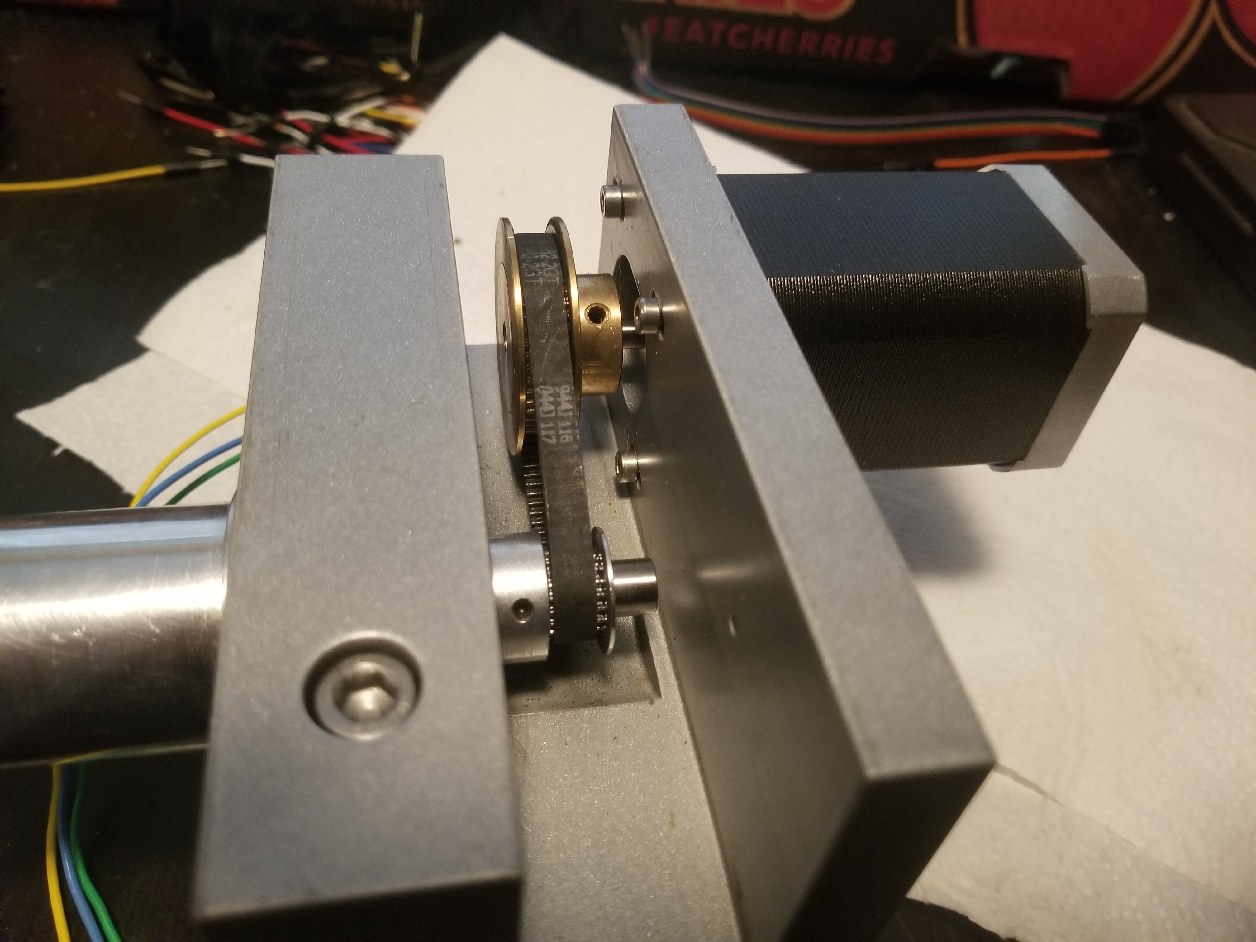
That’s a good question, the belt appears to be a 2MGT from the pics I’ve found so the Gates design manual for those belts is helpful.
There are notes stating that Vee groove belts are better suited to high speed applications than toothed.
These speeds would be, literally, off the chart for the 2MGT belt, see pp 17
from pp 12 step 2D calculating the Belt Speed using the supplied formula is key
pp 64-66 describe the tensioning requirements, Formula 1 on pp65 expresses static tension in terms of the desired belt speed. Once calculated these radial forces may be well over what the bearings in a normal BLDC motor are designed to support.
To add to that you could reverse the gear ratio. Rather than a 2.5:1 run it 1:2.5. This would increase the torque and reduce the RPM. You would have a max RPM of 20k.
Space constraints are real with the Nomad, it’s not possible to flip the pulleys but you can fit a 1.25" OD max pulley on the spindle. It will need machining to have clearance.
The belt speed limits are apparently dictated by the smallest diameter gear’s RPM in that chart. That motor and spindle running at 20 kRPM would have about the right amount of torque for a stock Nomad with a 1/4" endmill. Gates 3M HTD belts could do that based on the chart on page 41. If the spindle can handle that speed and both the spindle and motor can handle the required belt tension, that could double the MRR of stock Nomads without increasing forces. 50 kRPM would increase it by another factor of 2.5 - too bad the bearings in the motor aren’t well suited for direct use as a spindle!
That’s a swap to new pulleys as well as the belt then?
Did you check what static tension was going to be needed for those belts at that belt speed? Don’t want another wrecked motor from overtension situation like on the Shapeoko belts.
Nope, nor do I have any idea of how much speed or radial force the spindle is capable of, or if there is a way to get to 50 kRPM - which would be much better.
Hopefully in the motor specs there’ll be a max radial and axial load rating.
As for the spindle, the radial loads should be fine as it’s designed for cutting, if it can’t handle the belt static tension then the other end will be a problem. As for speed, as you say, we don’t know what it’s balanced to or what the bearings are good for.
There’s been a few posts from folks who’ve suffered broken stepper shafts after belt tightening, when I measured the actual belt tensions and then started checking the specs of similar stepper motors I came across warnings from manufactuers of fatigue failure causing shafts to snap if the radial load was exceeded peristently. We don’t want to do the same thing to the BLDC here.
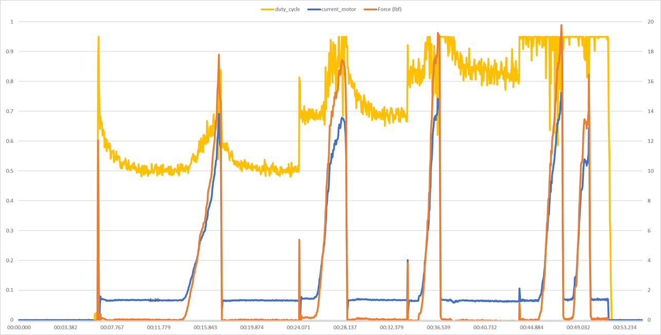
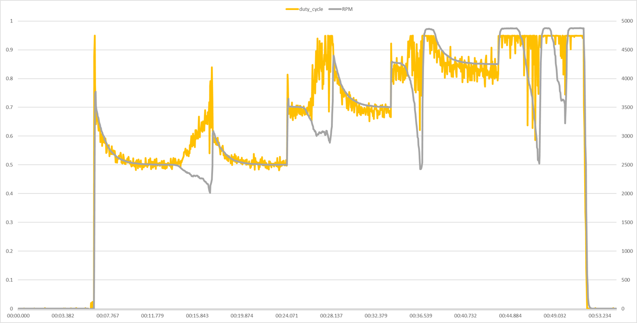
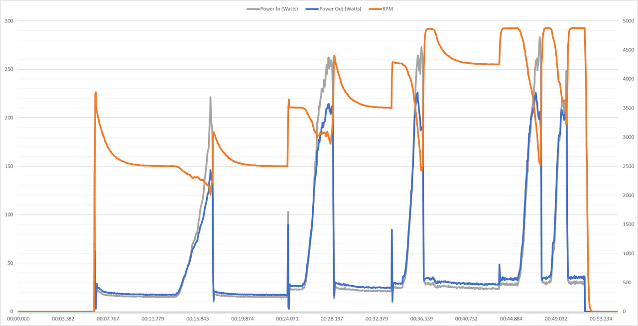
Looks like some overshoot in the speed controller. Charts assume that Kv = 190 and force would be for milling with a 1/4" endmill (double it for 1/8").
Going back to the “replace the motor” discussion briefly, does it make sense to replace the motor given that we don’t know what the spindle can and can’t take?
Replacing the controller is relatively straightforward and inexpensive, given that a VESC costs <$100 but those Maxon BLDC motors are getting dangerously close to the price of even a Mechatron spindle, disregarding the cheap stuff one can buy from AliExpress. It seems to me that rather than replacing the motor, I might be better off replacing the spindle and motor if I’m going to go down that path.
So I have the ODrive control basically working. Only problem is I cannot stop the spindle. If I issue an M5 in Carbide Motion the spindle keeps right on spinning. After quite a bit of banging my head into the desk I realized something. The PWM output on the Carbide Board is not going to 0. In fact an M5 command does not change anything. If I run:
M3 S2000
The PWM pulse width goes from 0 to 24. If I then run:
IMO replacing both the spindle and motor with a relatively compact, light weight, and inexpensive modified COTS BLDC router makes a lot more sense for Nomads and maybe even Shapeokos, if acceptable performance with them can be demonstrated.
The Carbide Motion board should bring it down to 0 IIRC. I had a problem with my other controller where if it wasn’t 0, the McGillicutty would keep spinning, sometimes in pulses if the voltage was low enough.
How are you determining that the pulse width isn’t changing? An oscilloscope, or something on the ODrive?
The carbide board is run into an arduino that is measuring the pulse width. That arduino is sending commands to the ODrive and reading values from the ODrive. It is also spitting out the values on a UART which is how I am gathering the data for the pretty graphs. Eventually I want to make a CNC.js widget that will take the data and spit it out in realtime. Right now though it is giving me fairly accurate data on the pulse width.
So CM -> Arduino ADC -> Processing -> ODrive and you’re looking at the Arduino’s ADC reading?
How are you powering everything? A problem I’ve run into in the past is that when using different power supplies, the grounds can be off by a little bit. In this case you can connect the GND from the CM board to GND on the Arduino.