I’m hoping you guys land on a brushless option I can comprehend and replicate, bonus w/ a 3/8 collet, and/or that the new Nomad coming out has a Z w/ a bolt pattern compatible with the shapeoko spindle brackets so that for those of us who want a nomad primarily for aluminum & brass projects, it’s not a major month-long electrical engineering project to make it capable. It’s such a tight, stout little machine, could even pop a couple threaded stays on it to triangulate the vertical X structure to square & really secure any flex out of it.
Maybe, with the heavier loads, we should stick linear bearings & ballscrews under the Y bed & off the backboard for the X too, I rather than the rods supported only at their ends. …if they’d even fit… I wouldn’t want to just build a machine from the ground up, but by the time I think about the obvious mods I’d make to the nomad, I’d be halfway here.
There has been talk of @Vince.Fab making a bolt-on kit for the Nomad I think?
I think I’m going to try it though. I’ll just go with ballscrews for now I think and only put linear rails on the Z-axis.
I think linear rails for the X and Y axes would work but I think you’d want to add some more material, not just use the backboard. The backboard is only ~6mm thick and has to replace some of the rigidity of the 20mm steel rods.
I’m really conflicted about the Nomad 3 though. On the one hand, it’ll be great that it exists but on the other hand it really sucks that there’s no upgrade path.
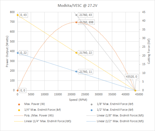
Here’s what @Vince.Fab’s Modkita should be able to do assuming that I didn’t screw anything up and the info that I have from him (max. current = 51.32A) and @CthulhuLabs (Kv=1600) is correct. Note the advantages of high speeds and large endmills (since power is proportional to MRR).
Looks like we need a bigger turbine housing with that curve. 36 volts or melt? @gmack
My ModKita is going back together soon, apologizes for being absent. Got a dream job and picked up a few more hobby cnc machines. Also I owe you a beer sometime, the workbook is gold!
Thanks - I’d really like to get that Modkita router model right (I’m starting to think that my current model is quite overly optimistic). Any data you (and/or @CthulhuLabs) can provide would help with that (PM works for me). It’s seems unlikely that you can really push it to those (36V) speeds though.
Something to keep in mind as well is that a motor design can only handle so much voltage. After a certain point the magnetic forces will become too much for it to handle and it will self destruct. As this motor is designed for 18V I’d be cautious going much higher.
I’m currently working with the ODrive guys to get it to work better. I finally got my own oscilloscope so I can provide data faster. From the looks of things there might actually be a bug with their hall effect code as everything looks pretty normal otherwise.
Nice work guys. I don’t know half of what your talking about, but I’ve enjoyed reading over everything.
I can’t seem to wrap my head around how PWM signals work, in relation to grbl and stepper driver. Anyone care to give me an ELI5 (explain like I’m 5) version?
The Shapeoko controller is a small integrated computer, it doesn’t have a lot in the way of electrical connections to use for different things so a lot of them are multi-role.
What many of the pins are able to do is turn on or off, that is 5 or zero volts output. This is how it talks to the outside world and changes stuff, it could, for example, turn on a light (LED) with this 5V output on one of it’s connections.
In order to talk to an analog world where things are not just on/off but vary it needs to be able to produce voltages between 0V and 5V, it does this by turning the pin high/low really fast. If this was an even 50/50 then the average output voltage would be 2.5V, if 10% of the time it was high and 90% of the time low then you’d get 0.5V average. This 10% is the Width of the Pulse in Pulse Width Modulation. 0% Pulse Width = 0V average, 100% Pulse Width = 5V average
(correct me here if the Shapeoko controller is 3.3 Volts)
When the GCode asks for a specific spindle speed the controller needs to send a request to the external spindle controller thing, this is commonly an analog 0V to 5V voltage signal. It is common for the VFD (Variable Frequency Drive) spindle drives to have a potentiometer (thing with a knob on the front) which you turn to change the voltage from 0V to 5V to set the speed on the front panel. If you disconnect that potentiometer and connect up the 0V to 5V output of the Shapeoko controller instead you now have a path like this;
CAM tool says “I want this cutter at this RPM” and encodes the RPM in the GCode
Shapeoko controller reads the GCode saying"16,000RPM Please",
the controller then thinks “hmm, 16,000 is 2/3 of 24,000, I shall wave my PWM output pin up and down with it on for 2/3 of the time and off for the other 1/3 of the time” and hope that something sees it
the spindle controller then sees this as an average 3.3V and sets the spindle to 2/3 of max speed.
If everything works out then the spindle speed set by your CAM in the GCode ends up as a spindle speed in the real world.
There’s a bunch of other stuff going on here because the ODrive and VESC are not quite like a standard industrial VFD and because there have been some problems with electrical interference and noise if the Shapeoko and spindle drive get directly connected but basically one of the following two things is happening;
the Shapeoko controller waves it’s speed leg up and down really fast
the other microcomputer that Cthululabs uses wants the speed number, not the average voltage so it tries to read how much of the time the leg being waved up and down is up and get back to the how-many-percent speed of the CGode
this other microcomputer then sends that speed request to the ODrive or VESC in a form that it understands
or
Shapeoko controller waves leg up and down
Other controller reads an “analog input” of the averaged voltage like a VFD would
So in grbl settings, I assume that’s where MAX and MIN spindle speeds values come into play, and PWM is just a percentage of a voltage to your spindle speed settings.
I’m possibly explaining wrong, but it makes sense to me. The analogy about the manual speed control was the missing link.
The GRBL controller needs to know the max speed and that needs to match whatever the spindle controller thinks is the max speed because max is just “ON” not a number.
I’ll leave it to Vince or Cthulhulabs to point out my silly mistakes
Sounds good. To elaborate on my specific ODrive solution, the pwm output from the Carbide board is run through a ground isolation board and into my Arduino’s digital in. My code figures out the pwm pulsewidth and then compares it to a look up table. That table maps a pwm pulsewidth to a specific RPM. The Arduino tells the ODrive to run at that specified RPM. In GRBL you set the MIN to 1 RPM and the MAX to 35000. At which point if your GCODE calls for 32500 RPM the ODrive runs that RPM.
if you want a different RPM range you just generate a new RPM map in the Arduino code.
It gathers data from the ODrive and spits it out in a CSV format. This is what @gmack has been using to generate his lovely graphs. Things like current draw, requested RPM, actual RPM, motor temp, ODrive driver FET temp, etc. It is also going to be watching the ODrive for errors and if one is detected trigger the GRBL board to go into a Pause state. This way if the motor stalls the ODrive will go into an error state and the arduino will signal the GRBL board to halt the job.