One thing that would be really handy in Carbide Motion would be to have a function for flattening materials directly in the program.
I currently need to create the flattening toolpath in CC on my main computer then transfer the file over to the one controlling my Shapeoko and run it there. This is annoying for a few reasons but the big one is that i have to measure the material dimensions, go over, update the CC project to have those dimensions, make sure the toolpaths cover the area i need to flatten, save it, copy it over to the control computer and run it.
An ideal functionality would be to select a “flattening” button which would bring up the interface
It would use the currently set zero point as the start
use the currently set unit of measurement
default to zero being set as the top of material and bottom left corner of the material but options for the other standard zero selections
inputs for length, width, height
input for how far down the surfacing should go
input for border buffer - this would give an amount in addition to the length and width to surface to account for uneven edges. So I might add a 1/4" buffer in the same way I usually have the box for the surfacing toolpath extend outside the material
The tricky part would come down to bits. This would need to be able to account for different diameters, RPM, and stepover. If it would be possible to easily export our bit library from CC that would probably be ideal and we could just select one from there.
Alternately, if there was a way for CM to have a rudimentary bit library, we could set up the bit in there and be able to select it from the list of defined bits.
Either way, I would be ok with taking a few min to set up one or two bits I usually use for flattening for this purpose.
I would think that the calculations wouldn’t need to be too complex. Ideally this would be a set, minimalist function because if someone wanted to flatten only a specific area or do a different direction or whatever other way they might want to use a flattening toolpath, they could just make a basic project in CC that would cover things for them.
I think it would also be totally valid to set the functionality so that it assumes some things that would make the interface and interaction much more streamlined:
require the zero point to always be at the top of the material
require the zero to always be the bottom left corner of the material
no thickness input because if you’re surfacing and measuring from the top, the material thickness is actually irrelevant because the only thing that would matter is how far down the thickness operation should go.
One extra feature that would be cool would be to have a perimeter preview where the head follows the perimeter of the cutting area (material dimensions + buffer) so we can be sure that the entire material is going to be covered.
Good idea. I had a glue up panel that needed flattening front and back before machining. I was thinking about flattening on my Shapeoko but I decided that it was faster to pull out my Dewalt planer.
If you have stepover, DOC, RPM & Feed, you don’t need to define a tool.
I would argue the time it takes to rifle through the tool library is no less than the time it takes to enter those 4 parameters, especially if they are in order & you can tab to the next field.
I think it could also be simplified by just entering 4 dimensions (-X, +X, -Y, +Y) from the current zero. User can allow for max size of stock plus any overtravel to start & end the tool off the stock.
The other ‘nice’ option would be angle, so you’re not locked in to X cut, Y stepover.
That’s a good point about the bit, that would definitely simplify things.
I do agree that entering the +/-X and Y values would further reduce the necessary inputs, however I think that might conceptually be harder for some people to grasp. It seems like one of the main desires with C3D software is to make it pretty beginner-friendly so that might be harder for some people to grasp.
That being said, it could even be simplified more if you manually jog the head to the bottom-left and top-right corners. Set the height from the top and you don’t need any other measurements.
So the flow might be:
open the interface
jog buttons to move the head
jog to bottom left, click the “set bottom left” button
jog to top right, click the “set top right” button
move to somewhere on the material, set the zero at the top of the material
possibly enter buffer, but honestly i’d just end up having the head out a little bit away when setting the two points so this probably wouldn’t even be needed
enter your DOC
enter RPM
enter feed
and you’re ready to go.
You could have the “preview” so the head moves around the perimeter to verify or you can just hit the “start flattening” which starts the job
You could also have the option to manually enter the X/Y+/- values or length/width for those who don’t want to move the head, but it wouldn’t be required
I’m not real familiar with the built in macros. If you can paste in Gcode, you could make a few different sizes, and run them from there. If these are not production it wouldn’t matter if you surfaced a 8" x 10" project, with a 12" x 12" surfacing program.
Comments on the dreadful state of public education aside…
If you are visually/manually setting the XY min/max, then why a need to set zero?
It could implicitly use the first (lower left) corner selected.
And you can set them with the tool off the stock, so the buffer is also unnecessary.
You’d still want stepover, doc, total depth, rpm & feed.
@Tod1d
The only zero needed would be the top of the stock because that would still need to be registered somehow but yes, if you saw what i wrote you wouldn’t need to set a buffer explicitly either.
As someone who builds interfaces for a living, I’ve learned that what seems blindly obvious to one person is completely a mystery to another. So trying to strike a balance between a “power user” and “beginner” is usually the goal, one that C3D seems to be doing quite well with so far.
Based on the comments that I’ve seen on the forums so far, the issue is less about the “dreadful state of public education” and more that people later in life who are exploring a new hobby are needing to start using concepts they might not have thought about in decades. So being understanding of the full range of experiences is an important part of the user experience process.
A good example would be someone who is starting up with little to no knowledge of CNC and they want to flatten their first board. Do they know that they probably should place the start point a little off the corner of the material to ensure that if they didn’t line things up perfectly it will all get surfaced? Likely they won’t.
Similarly, a “power user” or even just someone who’s more experienced with their machine might be completely understanding of that but their process is to zero off the corner and they don’t want to deal with re-zeroing after surfacing before starting the rest of the process. Yes, they could add the surfacing into their project file, but I know I don’t feel like it all the time and I’m sure plenty of other people don’t either. So having the option to add in a “buffer” value allows the user to set a zero point at their desired working zero, set a buffer to ensure they’re covered and all they’d need to do is re-set the z height which they could do without having to move the spindle since they would know how far their depth of cut is and can just re-set the z height to that much lower than their previous height.
@WillAdams I saw that script come up previously and didn’t really look into it but I think i might want to take a look and see if it’s something I can work with. One sort of challenge for me is that i use a touchscreen and don’t have a keyboard nearby so i might look at creating a graphical interface that would make things a bit easier for my specific use.
There are a lot of potential moving parts to consider for this sort of thing.
Ages ago on the old Shapeoko forums there was a thread where user interface and automation and scripting were pretty deeply discussed — not sure where things would fall out on that sort of thing now.
First consideration, how much is involved in doing this in Carbide Create?
Launch Carbide Create
Job Setup to set area
input Stock Width
input Stock Depth
ensure Stock Thickness is sufficient/appropriate
set origin to Lower-Left and Top of Stock
draw rectangle of desired size
input width
input depth
ensure it is at the desired location
assign appropriate toolpath
select toolpath (Pocket or Facing)
select material and tool (for feeds and speeds)
if need be, adjust Stepover
set Max Depth (and if need be, adjust Depth per Pass)
preview to verify
if okay, send G-code
So, anything would need to be simpler than that — unifying the two widths/depths and combining Stock Thickness and Max Depth and Depth per Pass trims this down a bit.
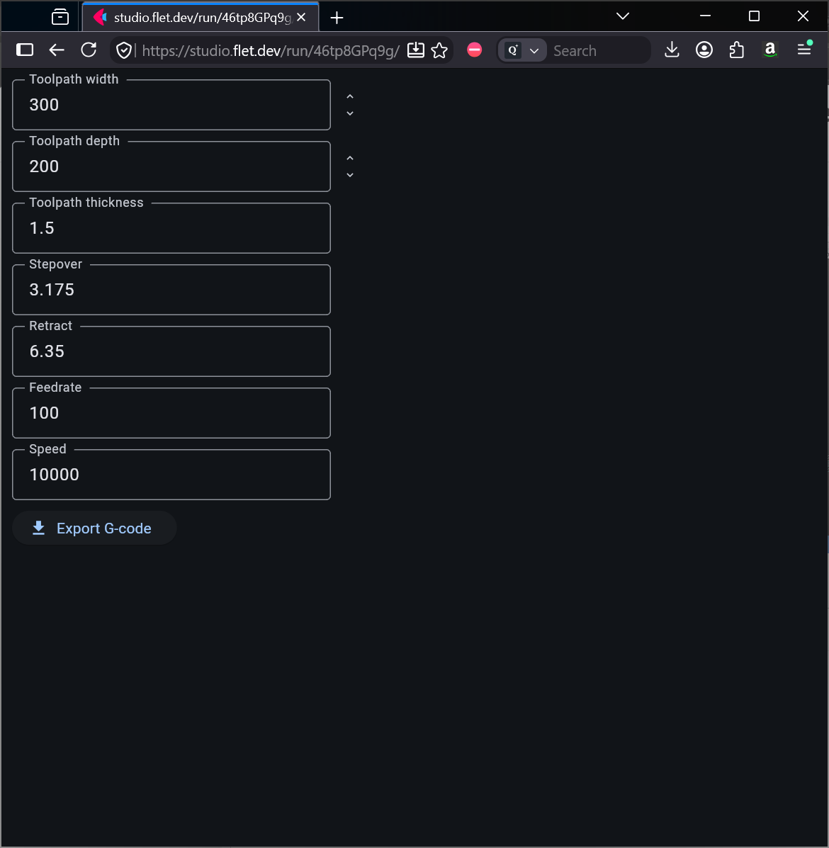
Given all that, the question is, what is an appropriate technology/programming system/graphical toolkit to use? Time was, I would’ve knocked this out in Runtime Revolution (now known as LiveCode) pretty quickly, and I’ve been waiting on PythonSCAD to release its next version which will allow GUI elements for input and, and I actually spent much of my vacation reading about PureBasic/SpiderBasic (but never got any traction, plus it got derailed by…) and then there was an announcement that flet.dev (Flutter UI for Python w/ various other technologies to make apps or web pages) had a 1.0 release, so I bought 90 bucks worth of subscriptions/tokens and almost got a workable tool…
A single page web app, served somewhere which could be bookmarked ought to be a workable option… lessee what I can puzzle out…
Well, i’m being asked to learn Rust programming for work so I’m getting started on doing something similar so it’ll be interesting to see the different approaches to the same goal!
“The reasonable man adapts himself to the world; the unreasonable one persists in trying to adapt the world to himself. Therefore, all progress depends on the unreasonable man.”
— George Bernard Shaw Man and Superman
Or, the old adage,
When someone says, “I want a programming language in which I need only say what I want done,” give him a lollipop.
— Alan Perlis
(interestingly, there is a macro package for (La)TeX called lollipop.sty which riffs off of that)
I might be interested in Rust if there was a nifty GUI for it and a programming system like to:
(which was a reasonable download and install and stand-alone w/ straight-forward instructions)
anyway, by re-working the code which I had from the previous project I’ve got a proof-of-concept which just needs for me to write some G-code boilerplate w/ variables and a loop…
Tested in Edge and Waterfox (I was still breaking and fixing it until just now).
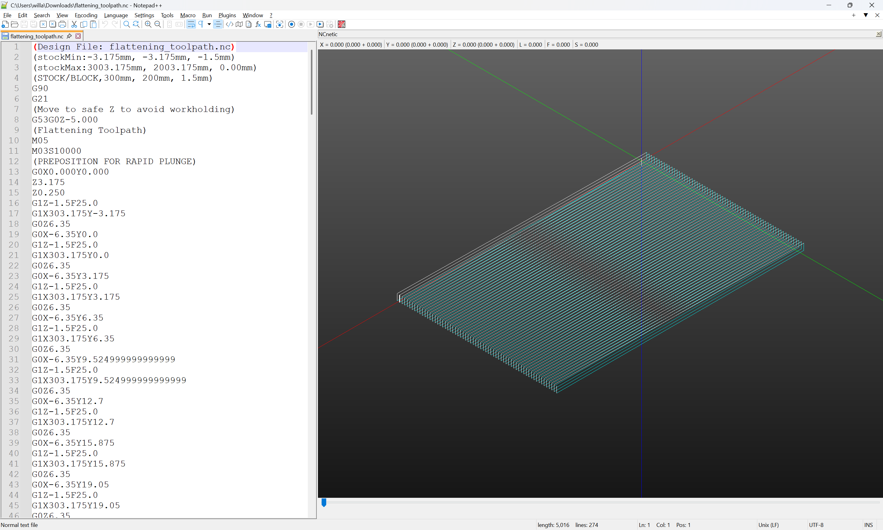
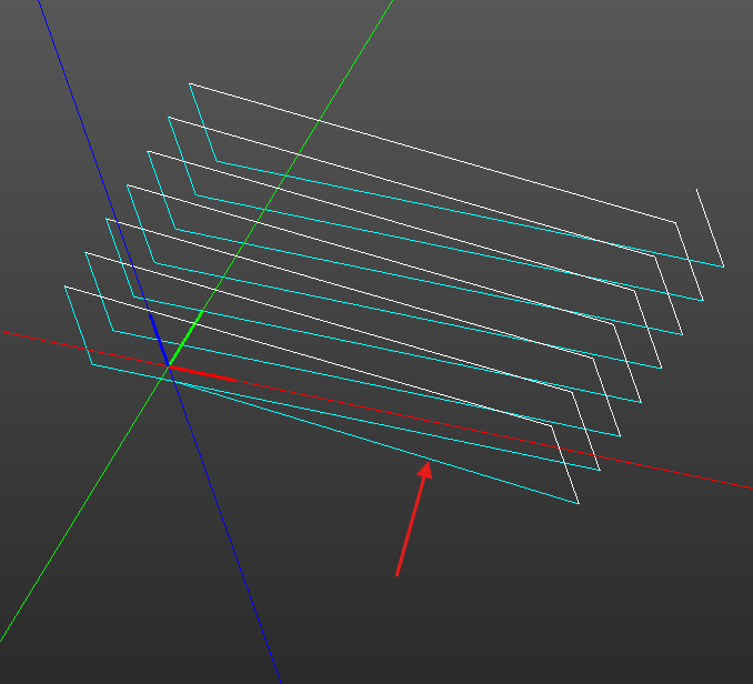
Please note that I haven’t had time to test the G-code yet (but it seems okay based on NCnetic’s plot as shown in the screengrab). It’s supposed to run w/ the current tool, and cut from the negative of the stepover in X and Y in straight lines to the right iterating until the Y-axis has moved to be greater than Depth + stepover and as far as Width + stepover.
Constructive criticism and bug reports are welcome.
Feedrates output as 25 (parameter is 100), and far too often.
Decimal places on some Y moves?
DOC?? When surfacing to get something flat, I use one cut at 0.001" (CC doesn’t like 0.000) and rerun changing Z if necessary. If shooting for a specific dimension, I’ll use multiple DOC. Or based on how much material to remove.
Did one yesterday with 0.050" max, 0.003" DOC (Sanding disc), and just hit Stop when it was cleaned up.
Parameters are “Toolpath” width & depth, not stock width & depth. Do you need to add the stepover as overtravel?
Units are millimeters (I’ll add a note on that). Decimal places on Y moves are because it’s a float.
Depth of Cut and Max Depth and Depth per Pass are all the same value.
There are additional feed rates because all passes are made in the same direction and it lifts and moves back to the origin.
Stepover is added as overtravel because my assumption was folks might use this for a McFly and want a side entry and the origin would be at the corner of the stock, but it might not be perfectly square/measured accurately, so overcutting by stepover all around seemed expedient.
EDIT: also, I had the preposition for plunge at 0,0 — now fixed to -stepover,-stepover
How about a toggle for units. Only difference in Gcode is G20 / G21
Does G1 need a redundant feedrate after G0?
Shouldn’t overtravel be MORE than tool radius? Especially if uneven stock is expected?
I usually don’t want it plunging into stock. Rather plunge/stepover off the stock, then cut across it.
In which case the overtravel is only necessary in the ‘direction of cut’ axis. (X in this case)
Or, overtravel in the ‘across cut’ axis (Y) should be cutter radius - stepover, so the first pass is removing the same material as the rest of the cuts.
I get the discrepancy between setting zero on the corner of the stock vs setting on the corner of the toolpath. Corner of toolpath for this type of path seems easier to me.
How about a zig zag (both directions) with stepovers instead of lifts option?
Adding a toggle for units raises concerns about feedrates and defaults.
I tried to copy the G-code as output by Carbide Create — if I missed something, that’s on me.
With the stepover set to at least tool radius, the plunge should be comfortably off the stock — conflating the two was one of the ways I minimized the needful inputs.
I don’t think I like zig-zag for stepover — making this cut unidirectionally was one justification for making it, since I’m not aware of a readily accessible free tool which cuts thus.
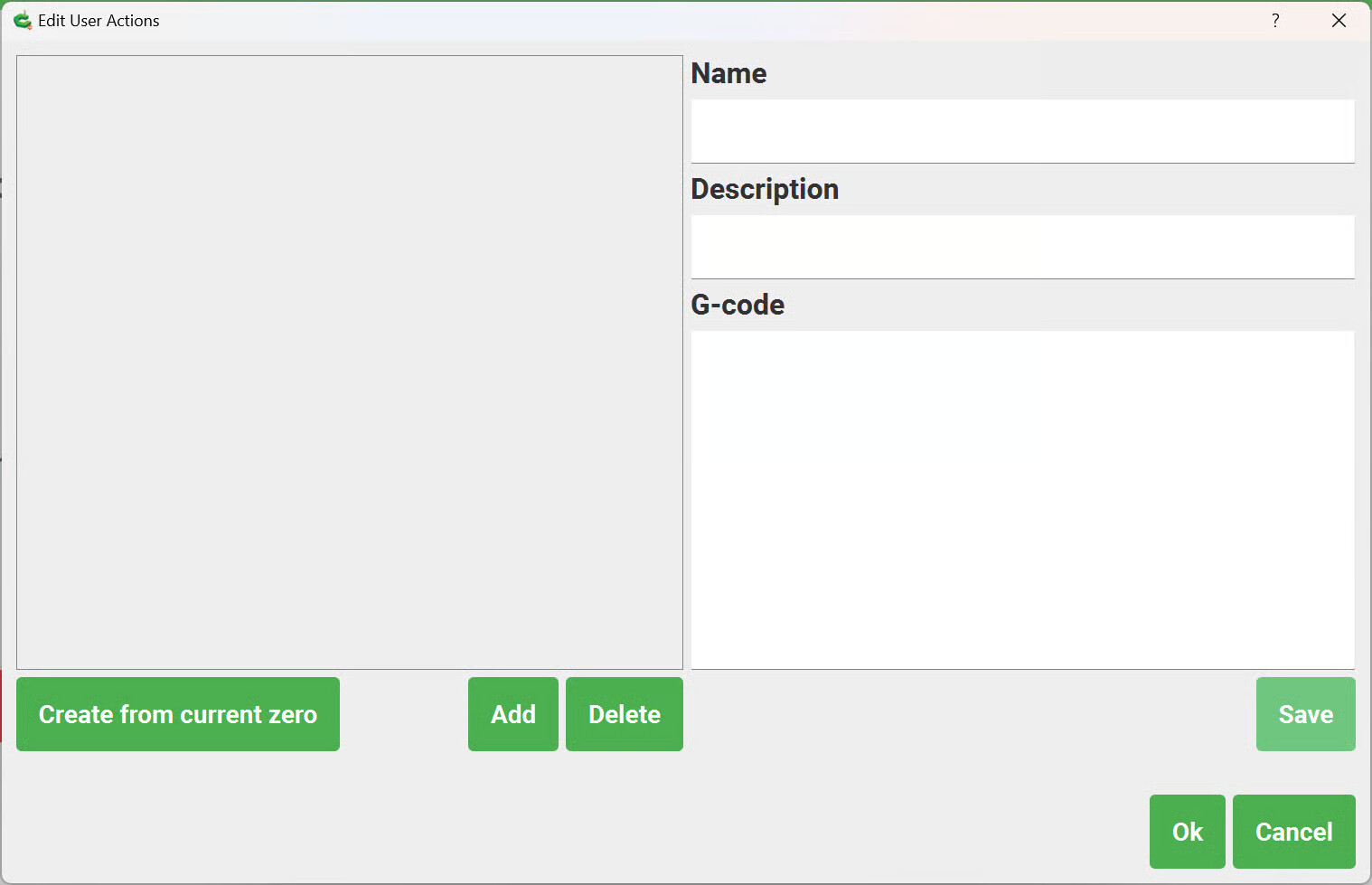
While I may get in trouble for saying this, I really wish that Quick Actions in Carbide Motion had options for UI inputs when run, and that there was a layer on top which would allow branching, variables, and loops — that would go a long way to end complaints of CM being too simple or lacking capabilities. Similarly, I kind of wish Carbide Create had scripting (still miss Display PostScript and Custom PostScript strokes and fills in Altsys Virtuoso on my NeXT Cube).
Arguably, all of this sort of thing ought to get off-loaded to other tools.
Towards that end, this link should allow viewing the code for the above tool, so folks who have familiarity w/ Python should be able to make a flet.dev account (there is a free tier) and adjust to their heart’s content:
Note: for some reason, had the wrong link — that should be to the flattening tool, my apologies for folks who clicked on the link and saw the unfinished AI-generated mess.
Where to draw the line on that sort of thing here is a good question. Maybe we can discuss tools which have synergy w/ Carbide Create?
A more robust macro architecture would be cool. But totally understand Rob has to balance things.
OK, so the glaring issues are…
F25 when F100 specified. If that’s a default plunge, then the F100 is missing on the cut line.
15 place decimals. Not sure the python command. tcl is round() or format()
Last pass at Y196.85. Should it not be 200? I know the surface should be done by then, but the whole slightly irregular stock thing…??
Indeed. And I’ll admit tunnel-vision in how “I” do surfacing / flattening paths.
I like to make sure I’m climb cutting at least around the edges so I’m not splintering pieces away from the stock. I also like to start both directions off the stock, so in your example I would start at
X206.35 Y-3.175
X-6.35
So my first cut is taking material.
So the best, common method that would suit the most users escapes me.