WillAdams
February 7, 2018, 3:21am
1
Please post any calibration files which you might have occasion to create to this thread.
Here’s a diamond-circle-square:
diamond-circle-square.c2d (6.5 KB) — note that this was prepared in an older version of Carbide Create and may not work properly in newer versions.
For CC514 and later:diamond-circle-square.c2d (59.3 KB)
For drawing up a file see:
The last one I posted:
no longer opens properly in current versions of Carbide Create, so here is how to draw up and assign toolpaths to one.
Begin by launching Carbide Create, going into Job Setup, and creating a 4" x 4" stock area with the origin set at the center:
[image]
5 Likes
mikep
February 9, 2018, 1:15am
2
My circle square testcircle-square-test.c2d (4.9 KB)
And my calibration spreadsheet to go with itShapeoko3-Calibration.xlsx.zip (14.7 KB)
2 Likes
@WillAdams , do I have your permission to use this for my tutorial series?
1 Like
WillAdams
February 21, 2020, 6:45pm
4
Yes, please, that’s what it’s for.
1 Like
WillAdams
February 21, 2020, 6:47pm
5
Which reminds me, we should try the idea of:
milling a pocket for the Probe
positioning it in the pocket
probing for Z to get a distance to use to calibrate for Z
probing the corner and then the opposite edges to get values for X and Y
2 Likes
I can honestly and confidently say I’m not a SME (subject matter expert) when it comes to calibration. But this is great, stuff. Working on a master list of topics, corresponding resources for said topics, and potential SMEs to reach out to for further in-depth details.
1 Like
DanStory
March 6, 2020, 9:41pm
7
I personally don’t do cut calibration, mostly cause I think that would take me longer and I’m lazy but also it adds additional variables (end mill wear, deflection).
I use a dial indicator with 2" throw mounted perpendicular to the axis I am measuring and a calculator like the one @mikep linked.
G20 G91
WillAdams
March 14, 2020, 10:03pm
8
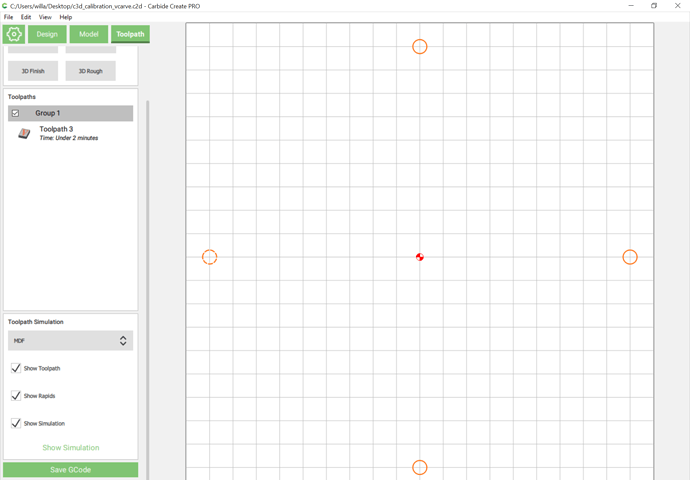
Okay, here’s the simplest calibration file I can work up:
Just 4 circles on 90 mm centers. Vcarve them with a V endmill which is more obtuse than the tips of your caliper and then measure the bottom center points with the calipers, then calibrate for belt stretch per: https://docs.carbide3d.com/shapeoko-faq/how-to-calibrate-the-machine-for-belt-stretch/
c3d_calibration_vcarve.c2d (14.8 KB)
4 Likes
Julien
March 14, 2020, 10:58pm
9
Brilliant! Do you mind if I mention this idea in the ebook? Much better than cutting pockets.
1 Like
WillAdams
March 14, 2020, 11:33pm
10
I don’t mind at all, sharing it is why I put it up.
2 Likes
