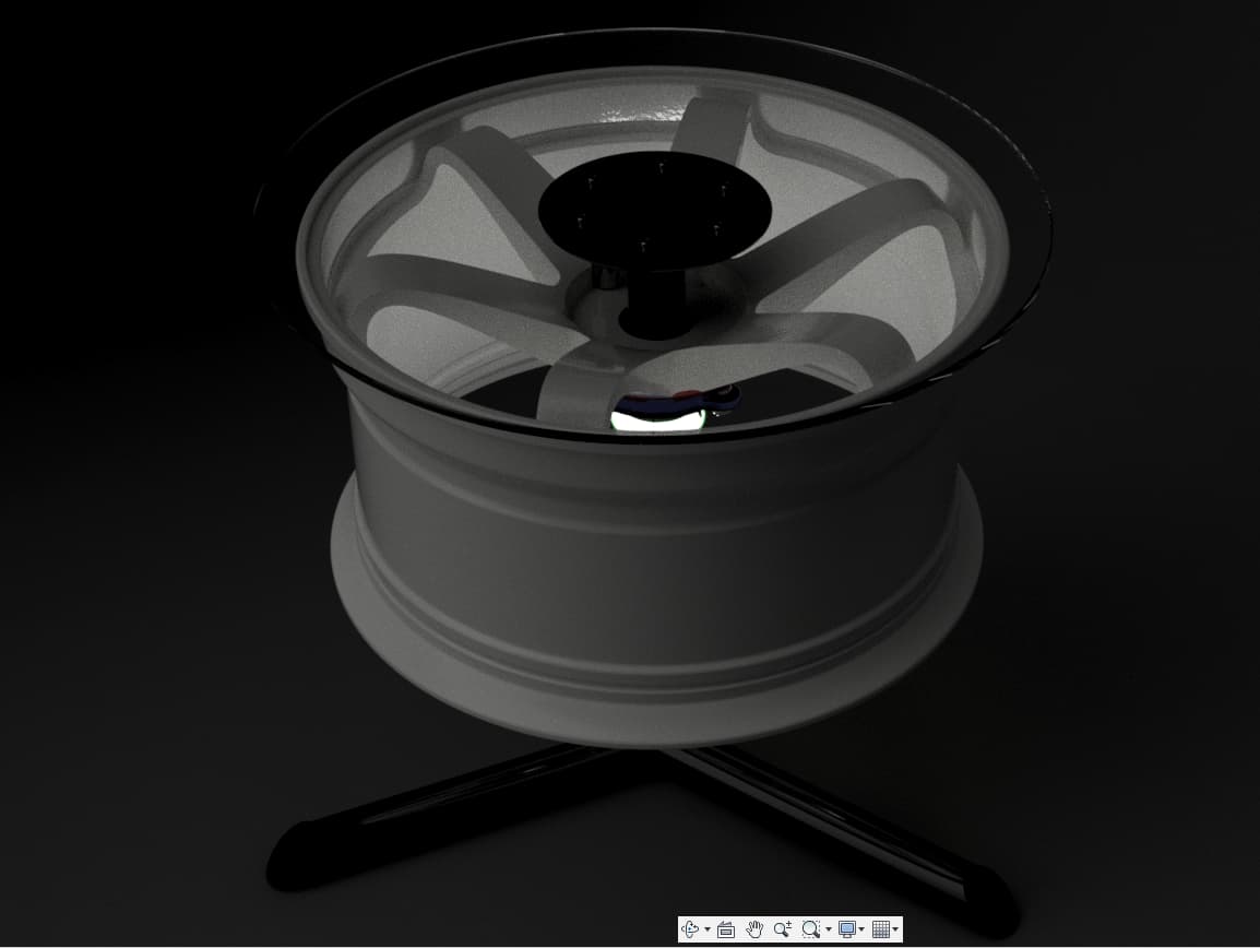
so i have a weekender car i was looking to fit some new wheels on, and had hoped that some Jaguar wheels would work, but the offset was too low, so I came up with the idea of turning them into end tables to show off the wheel, and they would fit the more modern aesthetic of my basement, once i finish renovating it.
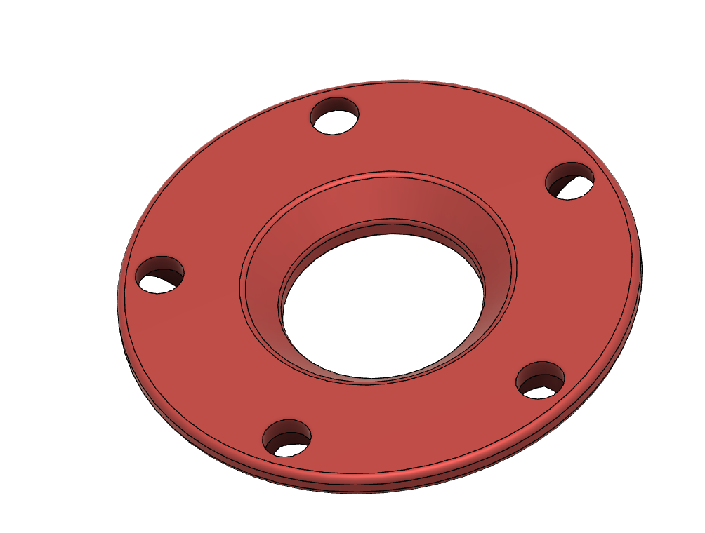
fully designed in Fusion360 with another wheel as a mockup. (wasnt going to kill myself modeling the jaguar wheel.)
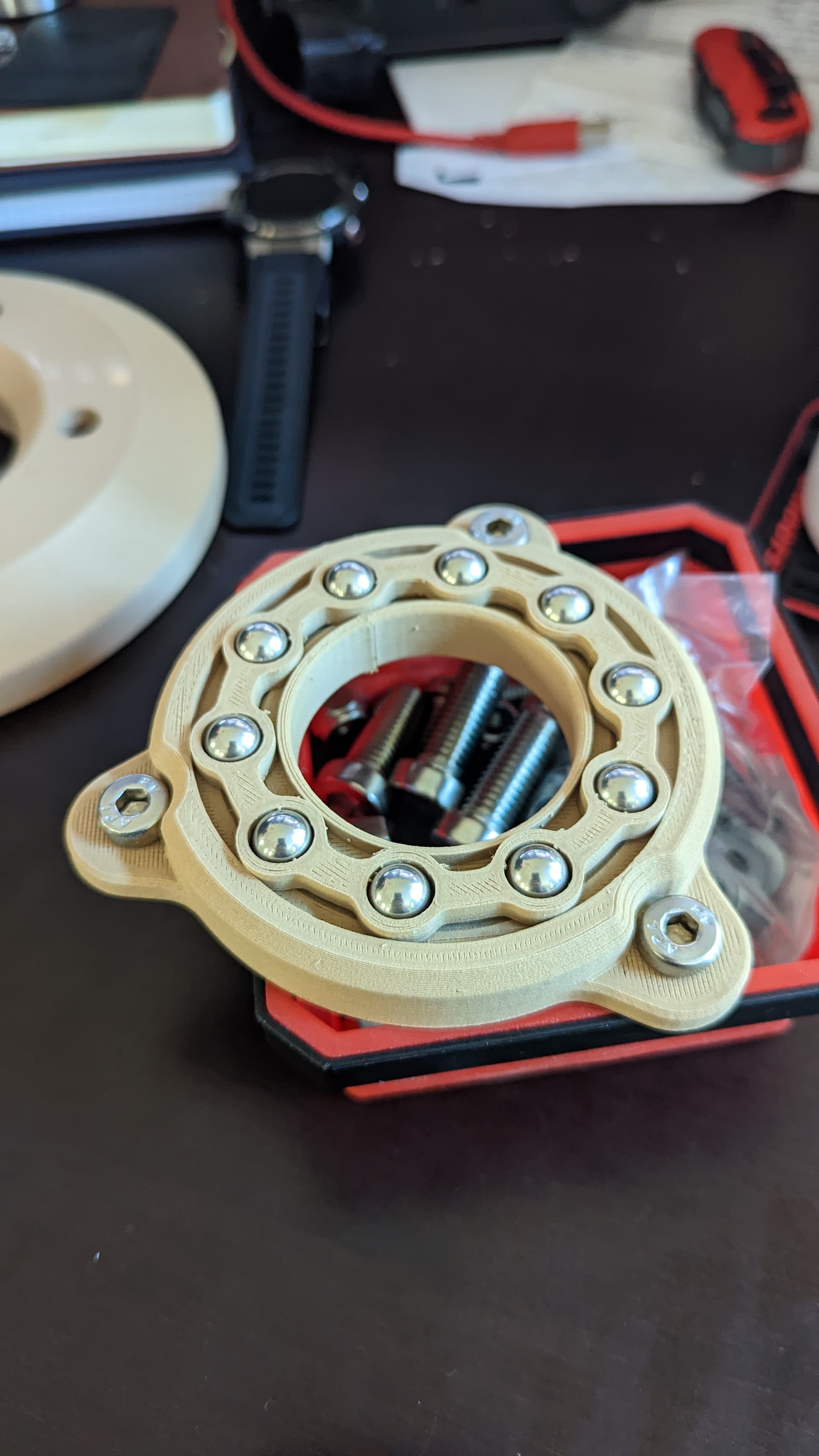
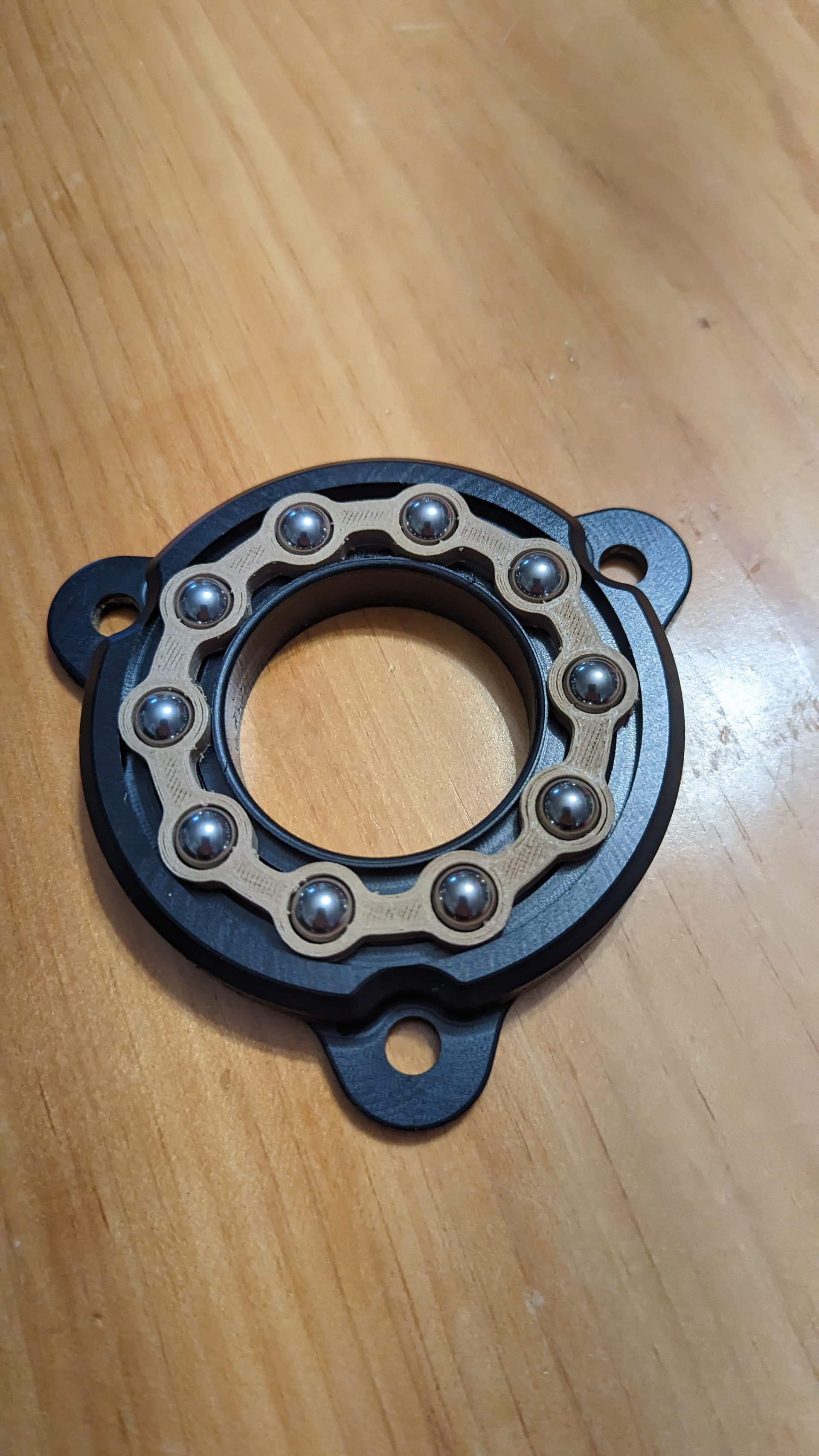
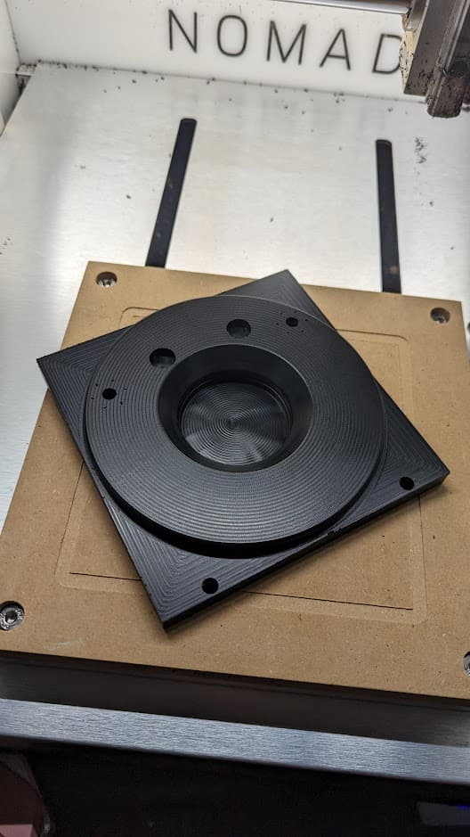
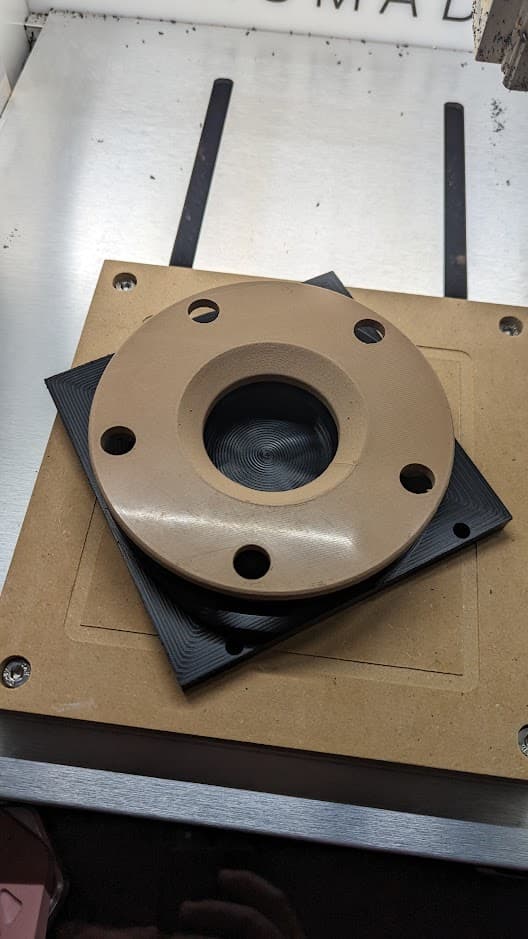
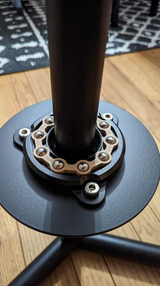
i 3D printed the bearings i designed with some wood filament i had loaded up, and once my Nomad 3 comes in ill machine them out of HDPE.
i recently added a small bracket that will shoot a strip of LEDs at an angle to backlight the wheel during low-light scenarios.
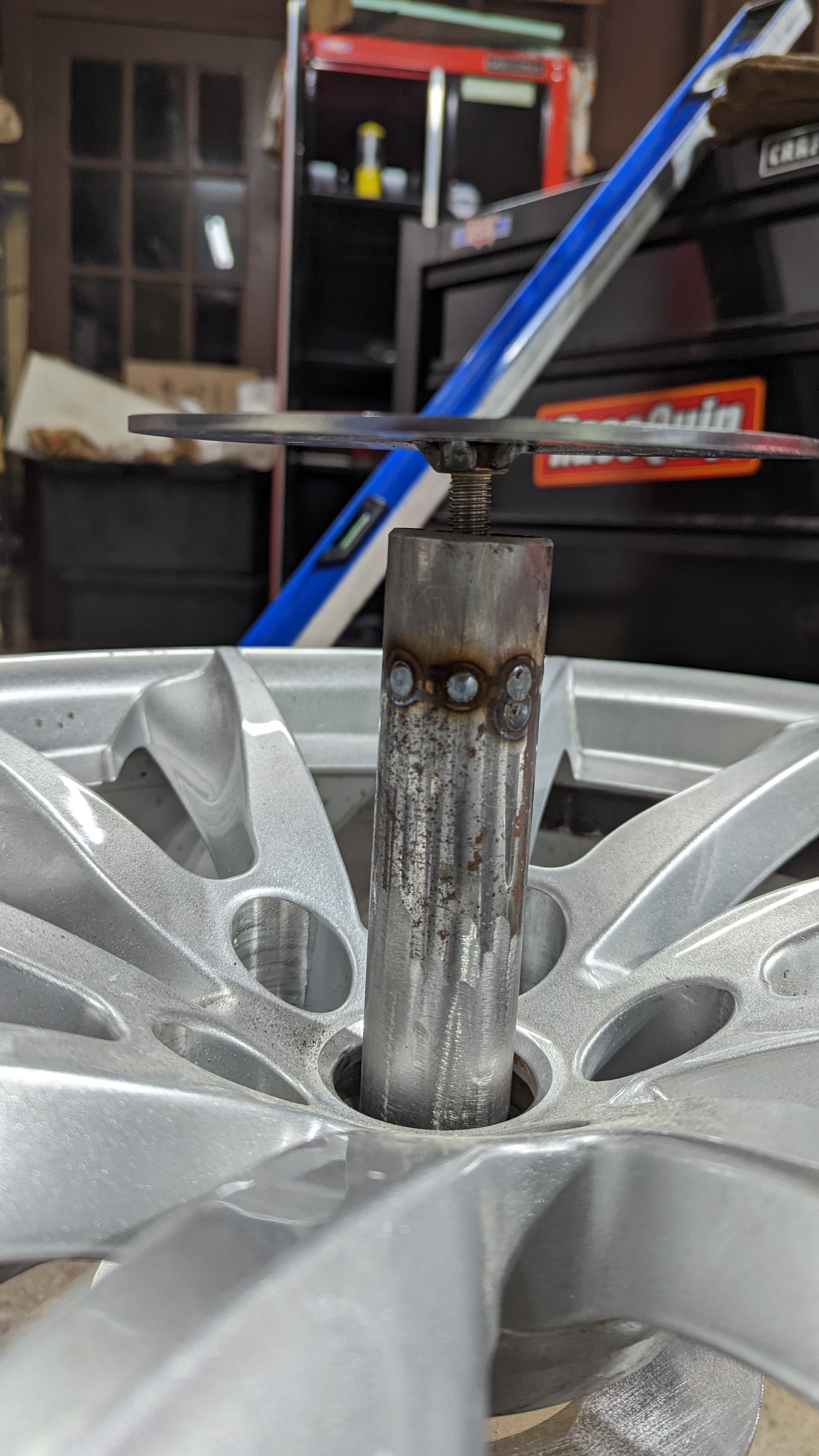
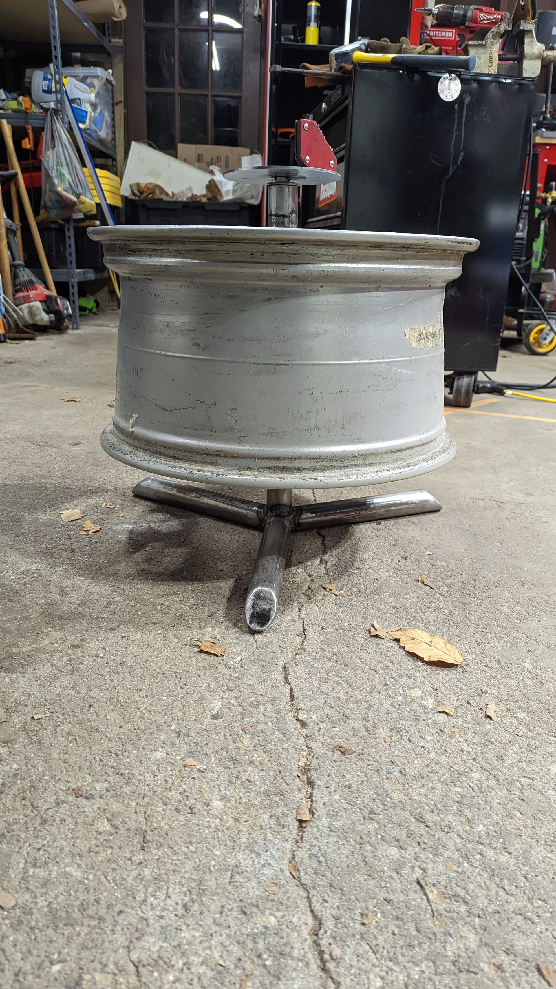
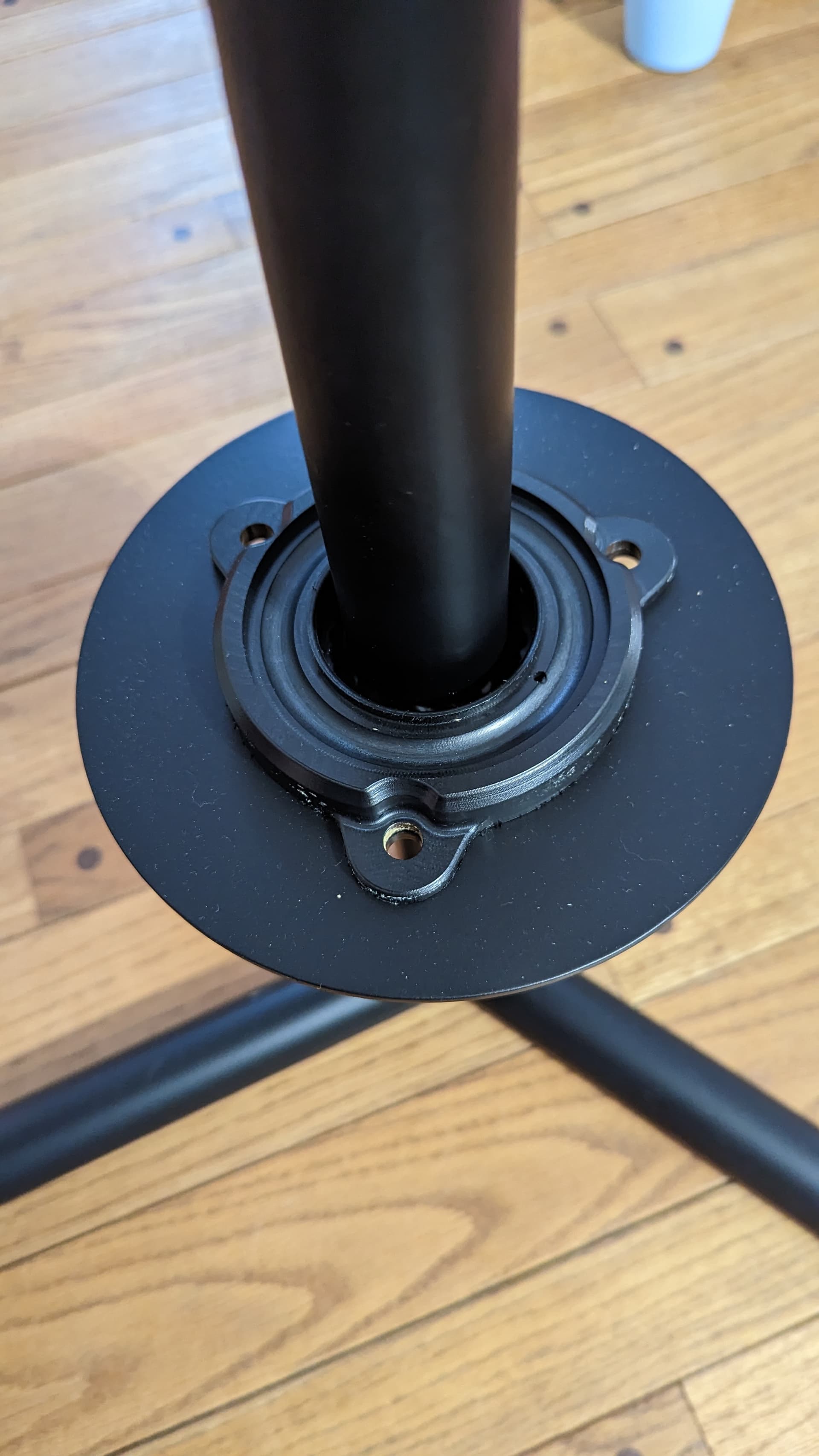
and here, the stand all welded up with the wheel loosely sitting on the 3D printed bearings. its insane how quiet it is for being a 3D print. i had sendcutsend laser cut the plates that the table top and bearing will sit on, because i needed to weld it to the rest of the table frame. https://www.instagram.com/p/ClWI-_irkfO/
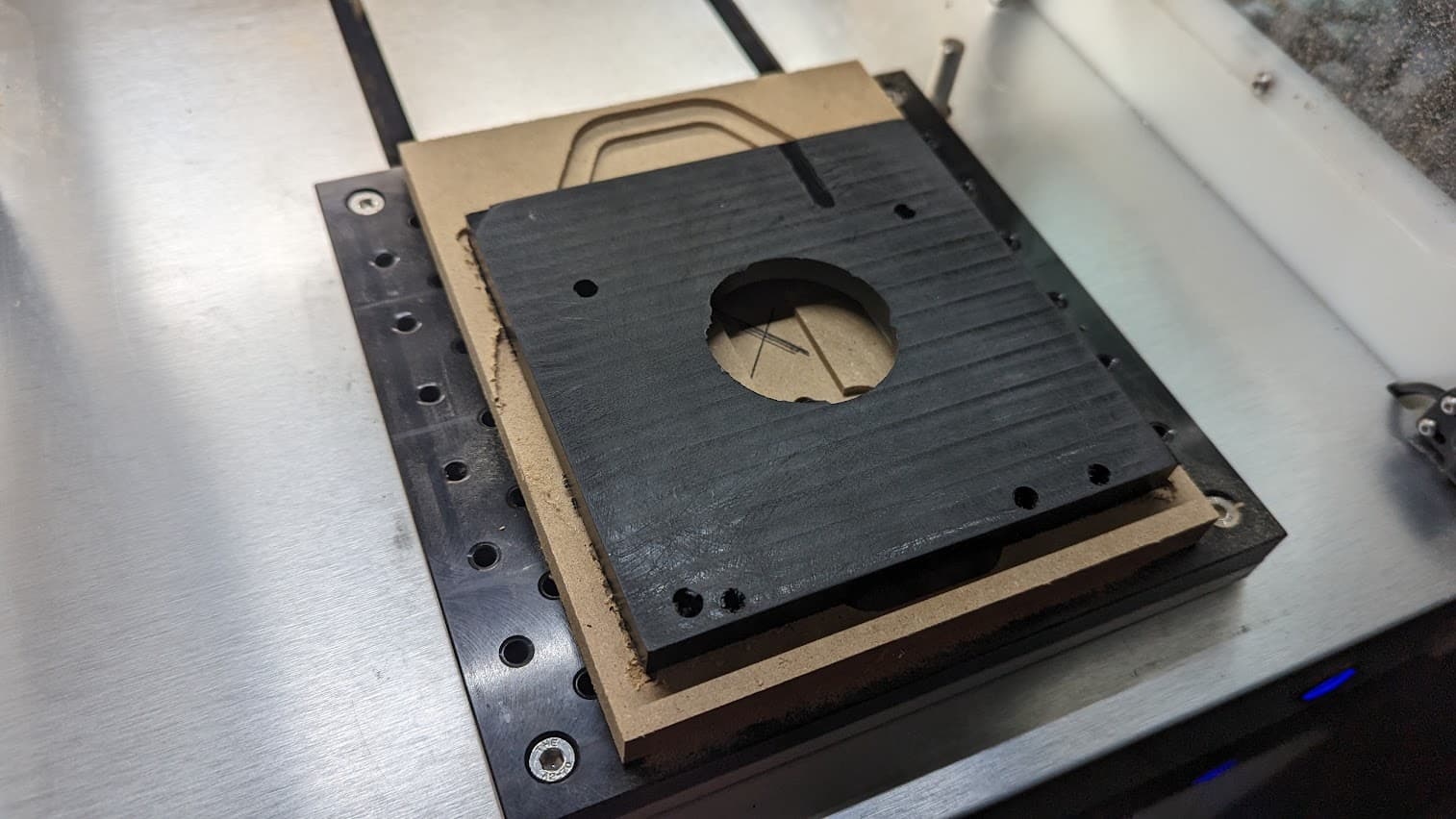
i have this old wasteboard from my first CNC that i did not like and eventually traded for a 3D printer, deciding that i should have followed the moniker “buy once cry once” and waited to buy a Nomad.
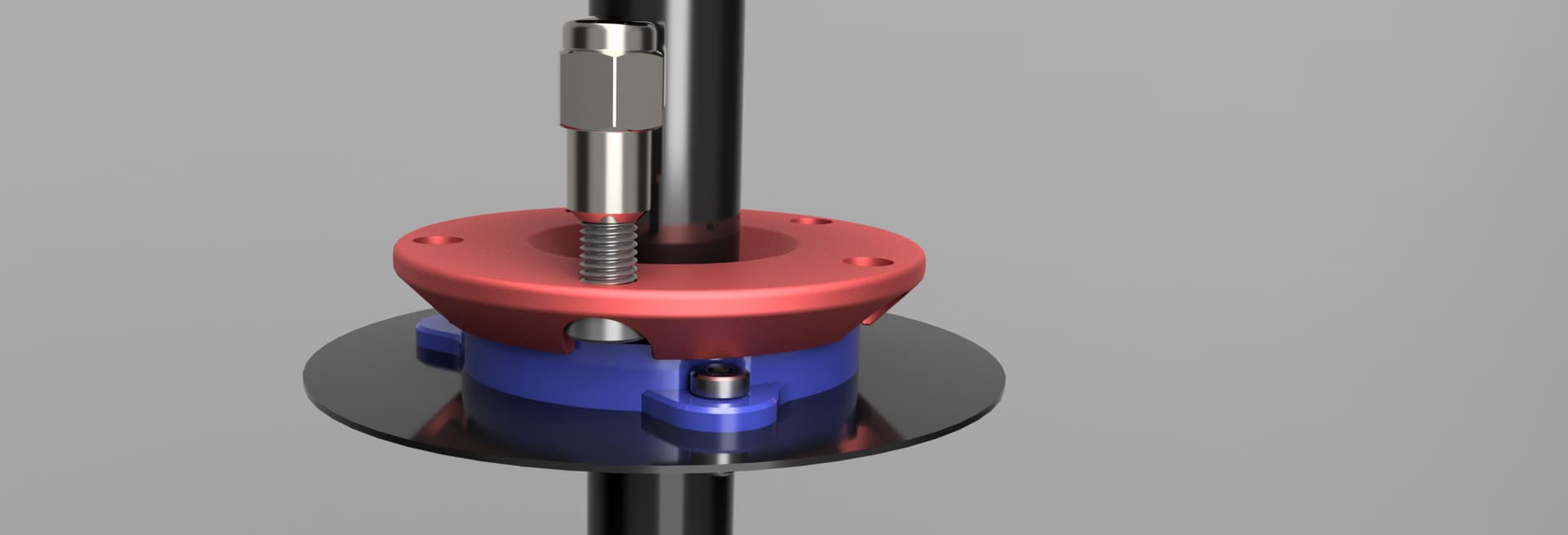
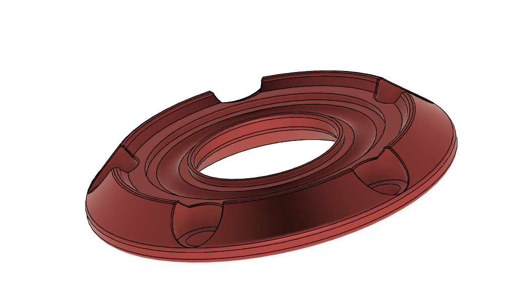
but, since i have this Starboard “stock” leftover, ill remove all the inserts from it, and cut it into a manageable piece that i can clamp to the Nomad and use it as a test piece for validating some toolpaths for the bearings. I figure HDPE/Starboard/Delrin should be a perfect material for the bearing halves, shown in blue & red in the pictures above.
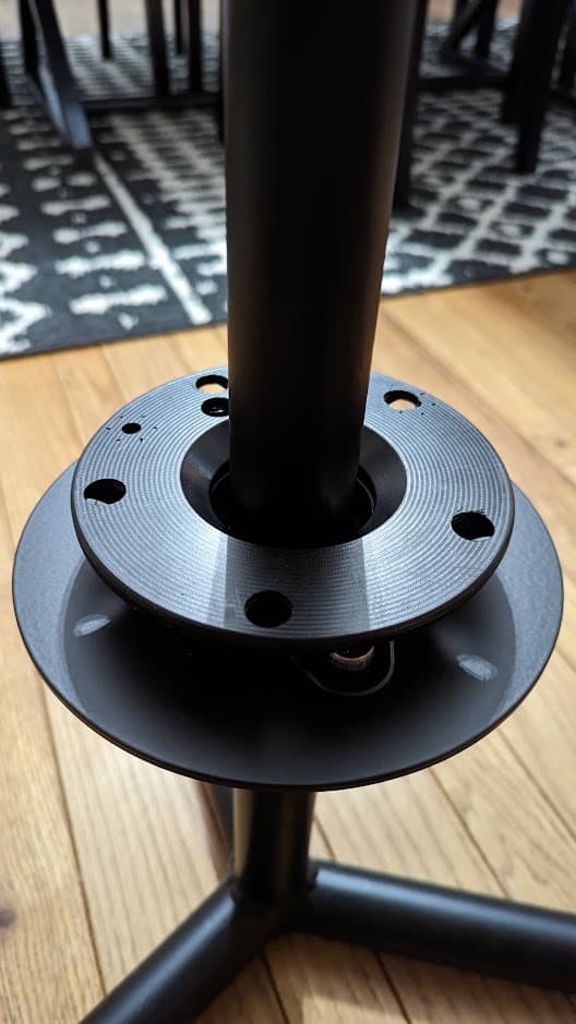
this was my first version of attaching the top plate to the table, but after looking at how finicky it was to get set up, and no better or faster way to streamline the process if i decide to try and make this something i can sell, i decided to design a bracket that i can machine that will press fit onto the main upright, and then have the top plate and glass bolt to that.
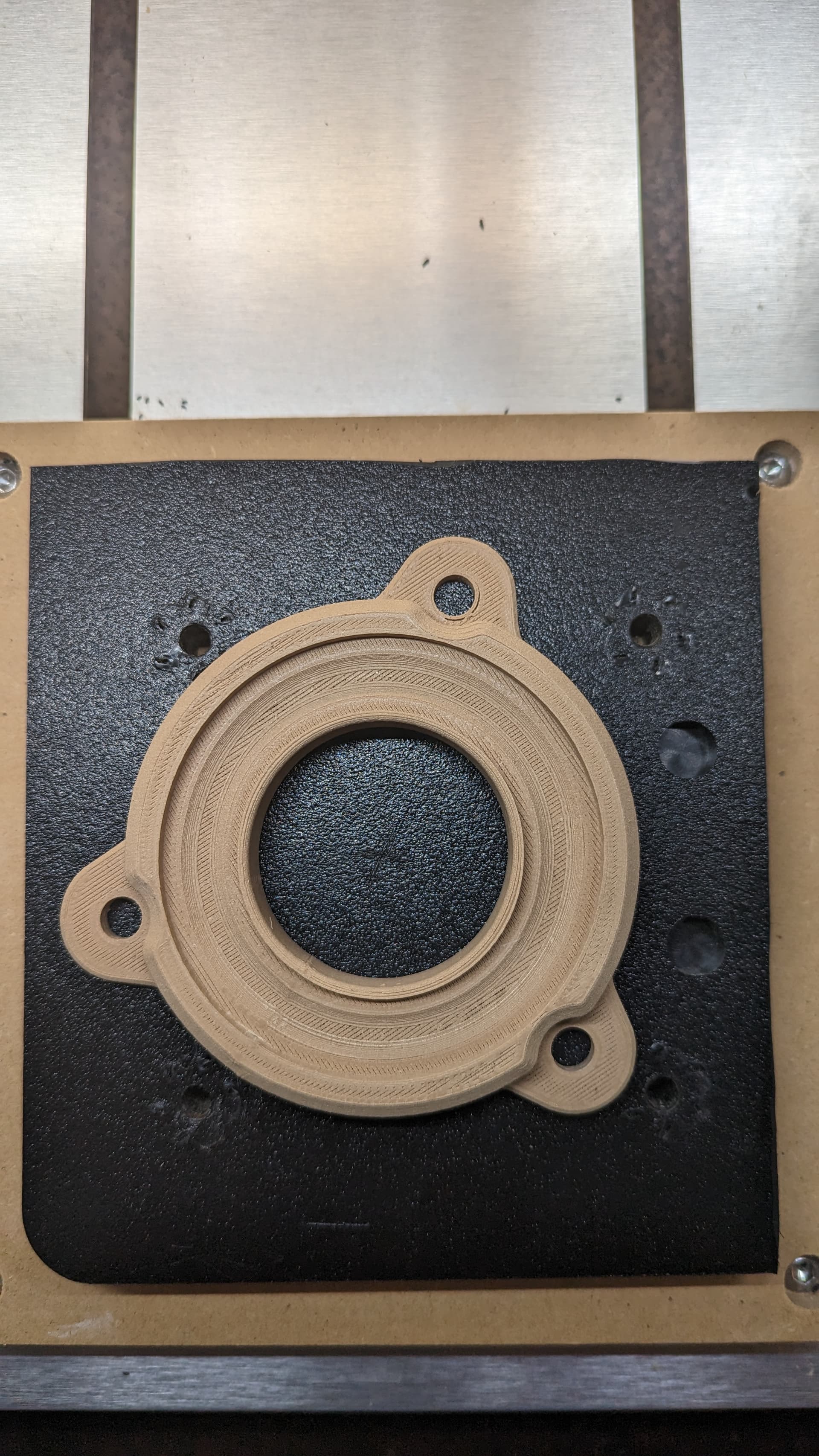
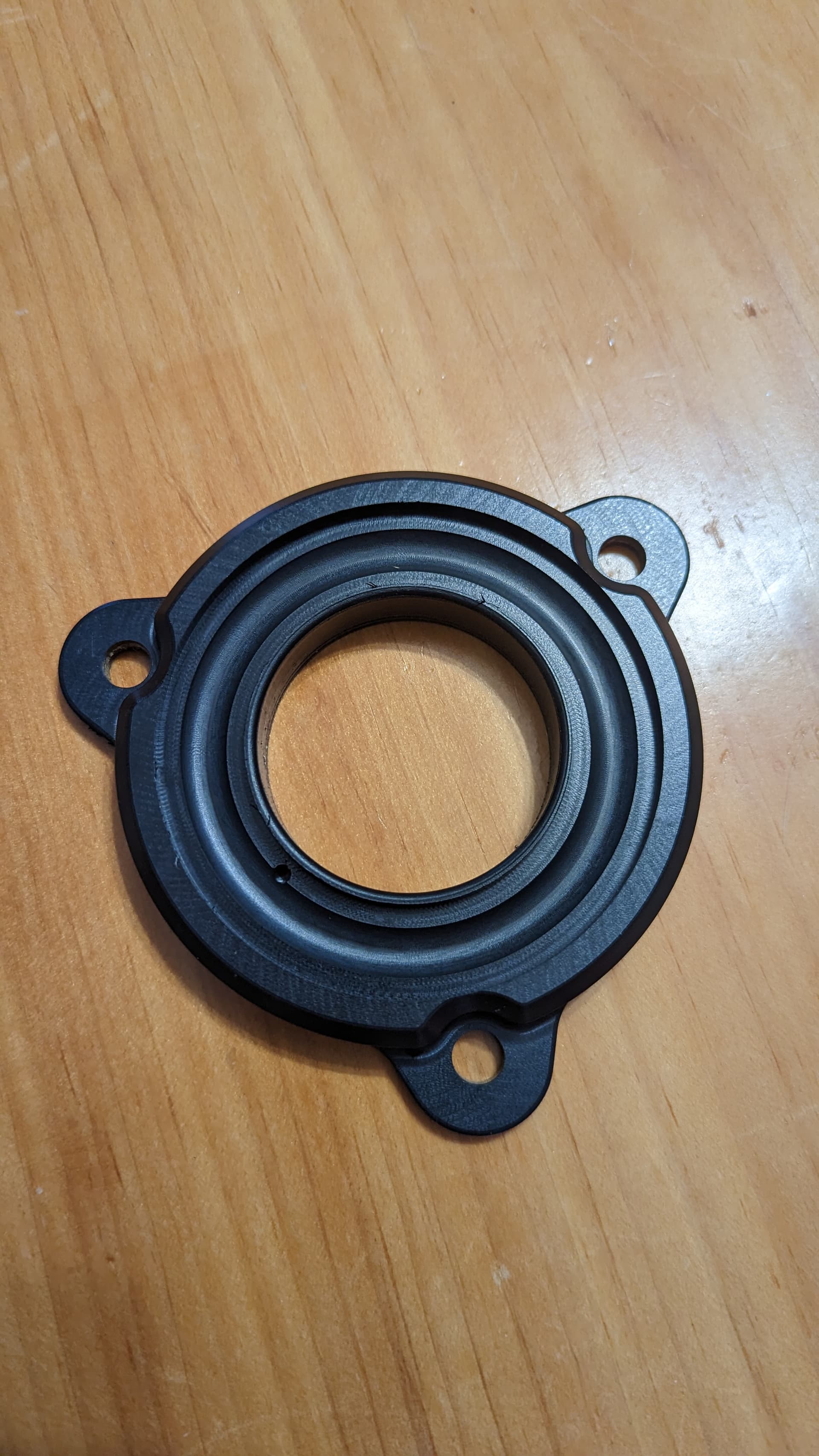
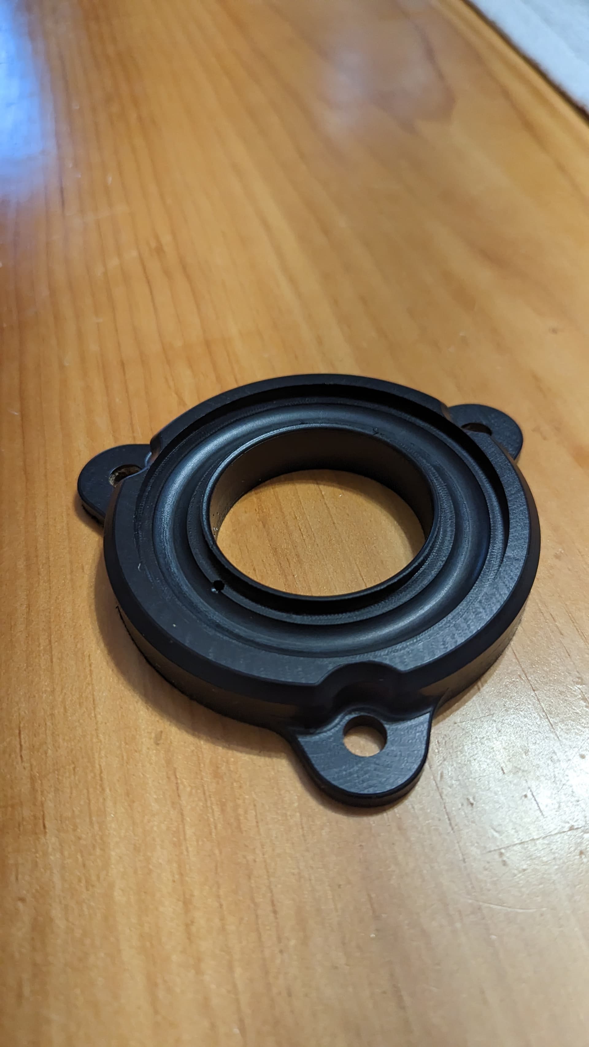
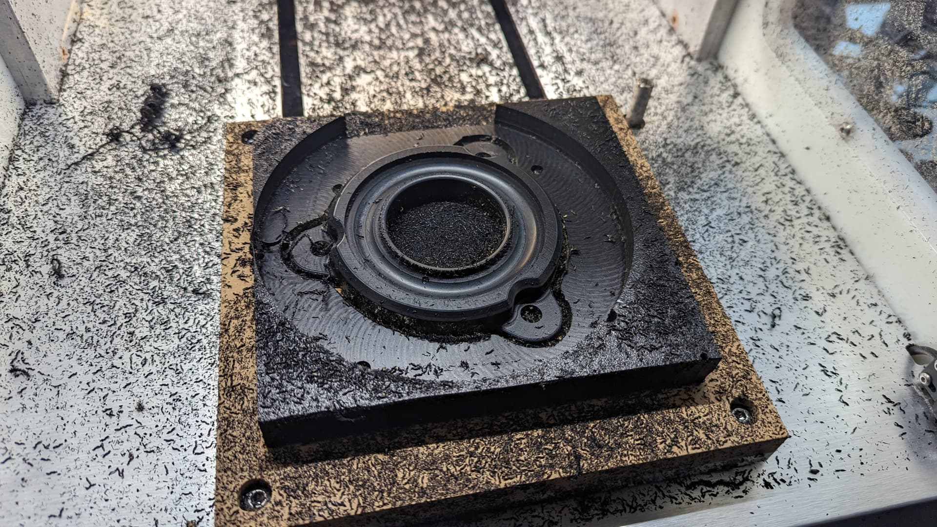
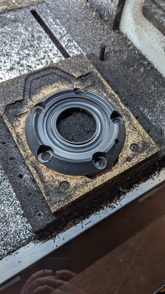
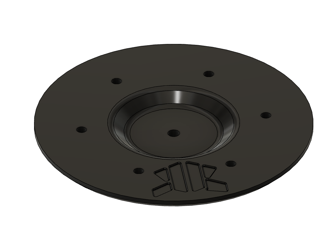
bottom half of the bearing is done!! ill probably take a quick break to finish my maker coin since i need to come up with a way to flip the top bearing half, either a fixture or some dowel pins.
The nice thing about designs w/ holes in them is one can use the holes to fixture — machine the holes, then secure through them into a fixture which has matching holes/threads, then secure the central hole and fashion a plug/fixture to secure it through that so that you can remove the five bolts around the perimeter and finish the part, then make a matching fixture for the other side and repeat the process.
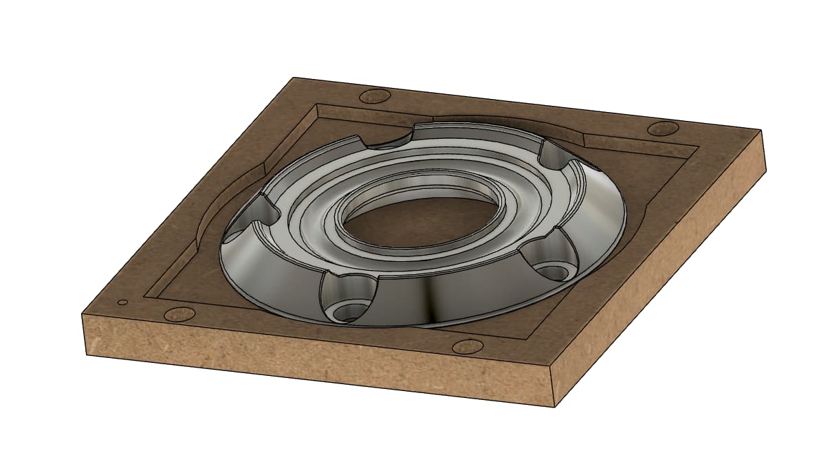
in the first operation, i would do the big center bore, hog out a bunch of the outer material so i can do the outer profile, and the fillet. the stock would be held in with double sided tape in the corners. double sided tape so far works well enough for this, and i can zero of the center of the material, as i dont really need to know any specific locations on the stock at this point.
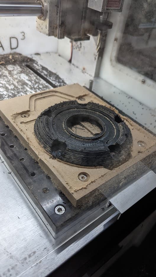
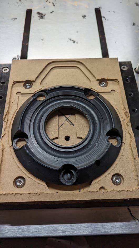
from there, i can flip over the stock and push the circular part i have cut out into the circular recess. I can cut off the majority of the hat with a contouring toolpath, and manually remove it, or turn it into chips.
from there, i can finish the rest of the part with any needed toolpaths.
Do the second op in two stages, hold down your part with the center hole, and machine your five lug holes. Then hold the part down by the lug holes, and finish the part.
thats pretty much what i was thinking, just trying to see if there was an easier (i.e. lazier) way to do it without the fixture also needing to be a two sided process & require inserts.
i havent really thought of a better way, and double sided tape seems to work well enough for holding down HDPE so i think thats what i am going to go with as my solution.
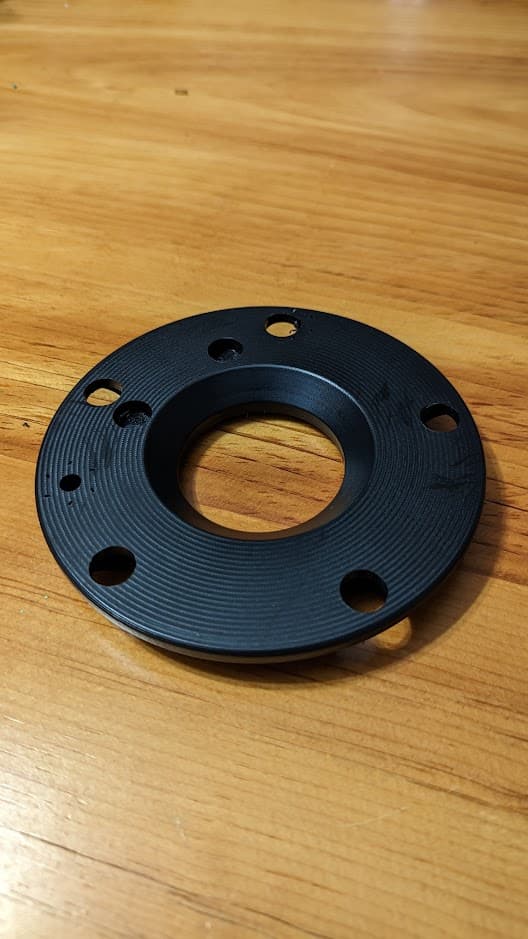
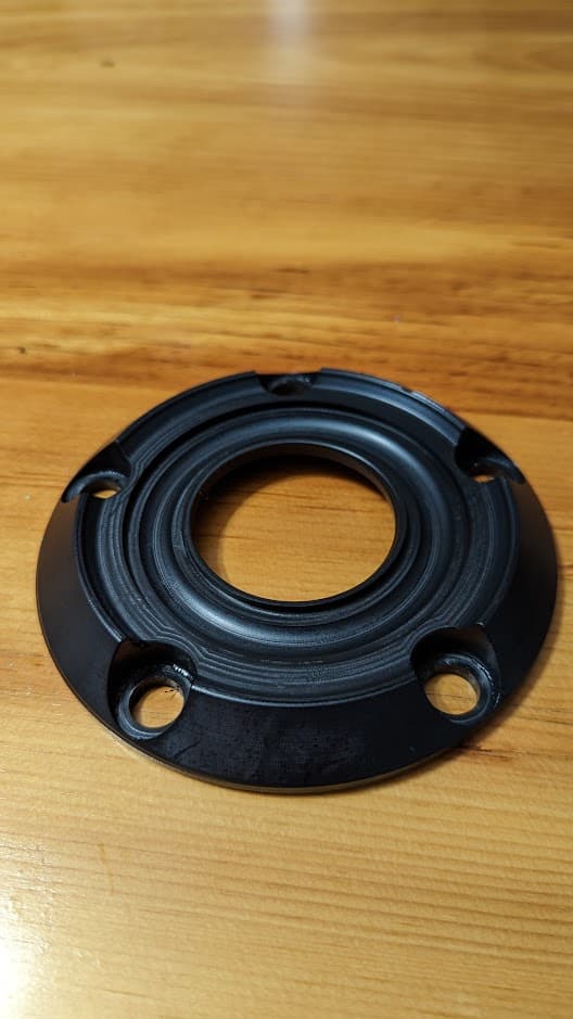
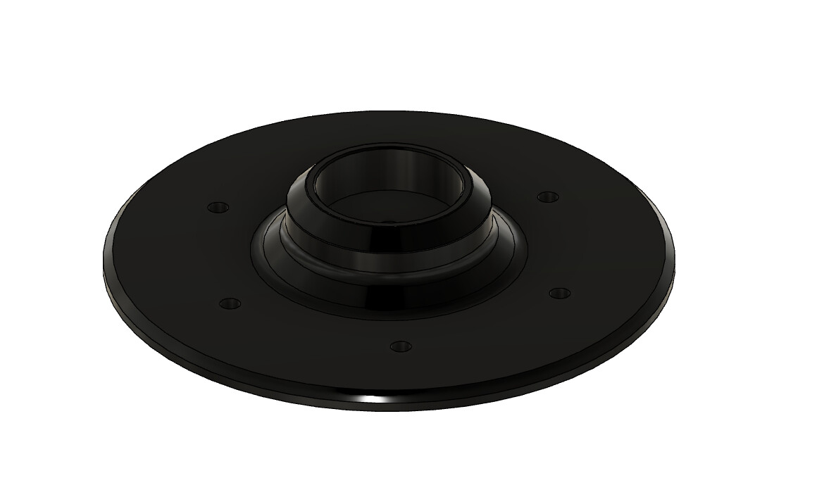
the wheel side of the top bearing is done, and re-used the maker coin fixture since i dont plan on making another one of those using that fixture, and working on toolpaths for the ball bearing side.
i think i finally have all the toolpaths built to be able to crank these parts out if this idea hopefully becomes as popular as i hope it does.
now to write out how the setups need to progress and verify my toolpaths are in the right order so i can export the toolpaths in the different stages, since ill need to fasten the stock 2 different ways for just about each setup to be able to complete each part.
i think its about as efficient as I can get it, but i did just notice that if i end up doing this part in multiple bolt patterns ill need a fixture for each bolt pattern which will be annoying, but i should be able to copy and paste the setup, and just re-select the features & such needed on future models. but im probably getting ahead of myself.
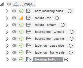
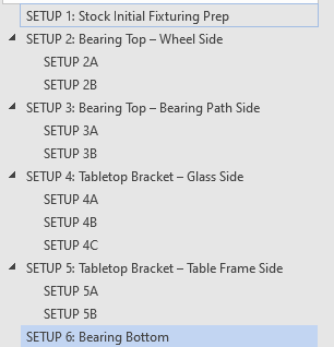
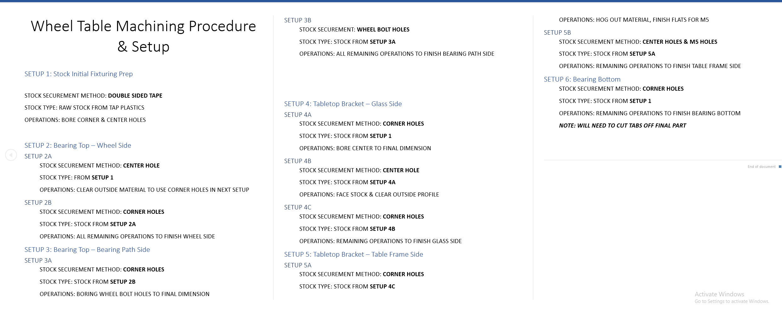
i wrote out a word document to identify the setups and what they need, and how the stock should be secured. my zero point is always the fixture, to keep things simple, so that never changes.
the aforementioned document on how each setup needs to be secured. Ill have to export each set of gcode and assign them names that align with this document.
this will be the next part to machine, but i want to validate it will work with my 3D printer first [which unfortunately is down since i had a failed print that globbed up all over the hotend and ripped out my the sensor, so im waiting for a replacement.
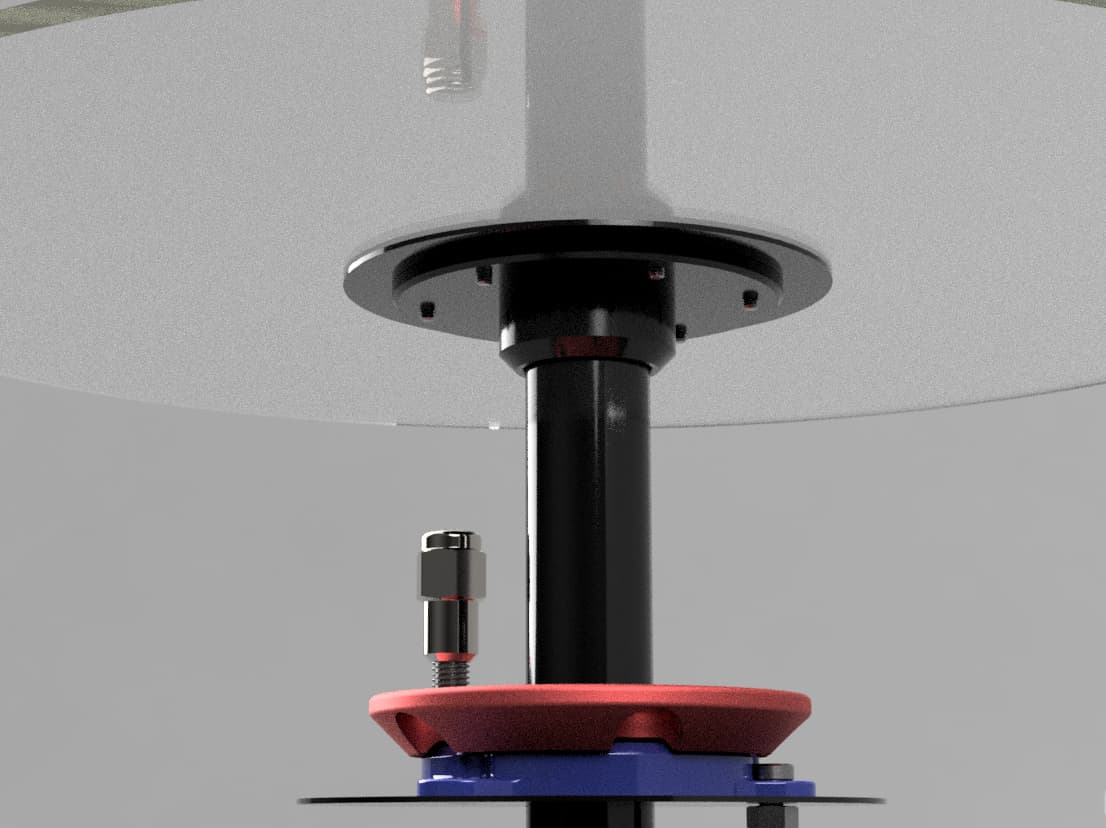
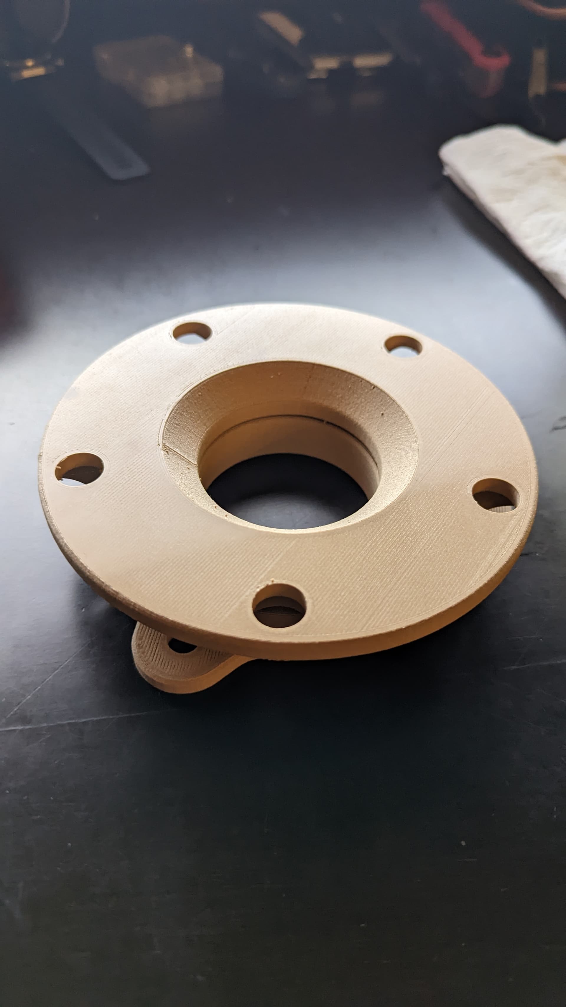
I originally planned to just use a metal plate cut from sendcutsend for this purpose, but a friend mentioned that having the center cap somewhere in the table could be cool, so i made this bracket that can be secured using a nut welded into the upright tube, if necessary, but its designed as a press fit onto the center tube that will keep the glass top in place.
the recessed area should be large enough to fit most center caps, but would require them to be modified by cutting off whatever mounting solution they use for actually snapping into the wheel, but i dont really consider that a negative, because the idea for this table is that someone is using a wheel that is otherwise un-usable, and meant to forevermore be an art piece as part of the end table, so modifying the center doesnt affect its usage.
and i added my logo, because…well its a perfect place to put it.
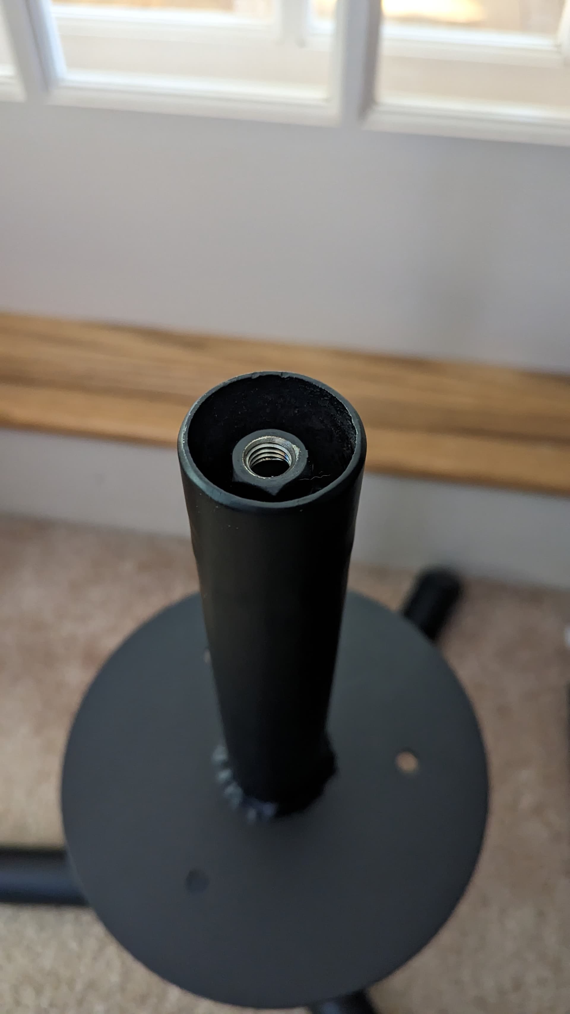
this nut is welded to a small length of tube, which then is welded to a small plate that is plug welded into the main upright. its pretty finicky to do, so my goal is that the press-fit nature of the top bracket is enough to keep the tabletop in place, but if i have to add the center nut, ill design a small little plate to be made by SCS & use a longer coupling nut for easy fabrication. that would make that process much simpler to implement and reduce any inaccuracy trying to make sure my pipe cuts are square, to the plate/parallel/plum to the bolt that would be used, etc.
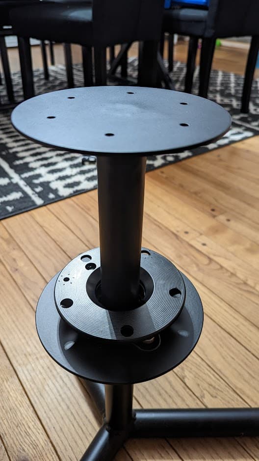
also, i assembled my table before refining the shape for the bottom bearing plate to use less material, so my plate is this mahoosive circle, rather than the slender shape in my render.