I’m making progress. Using CC 764. I’ve wanted to try this for a long time. Now I have a good reason - My daughter asked me to build a wedding box for her, so I’m practicing inlay techniques. I want to inlay names (using hard maple) into a walnut lid. I followed the advice of @robgrz to the letter (from this thread: Inlay mode for Carbide Create). Used .2" Max Depth and .01" Bottom Gap. My first attempt was a loose fit. So I took a step back and tried to take out all the chances for error: I surfaced the wasteboard; I used my drum sander to make sure my stock was perfectly flat and consistent in thickness; and used my bit zero instead of the “paper” method to zero Z.
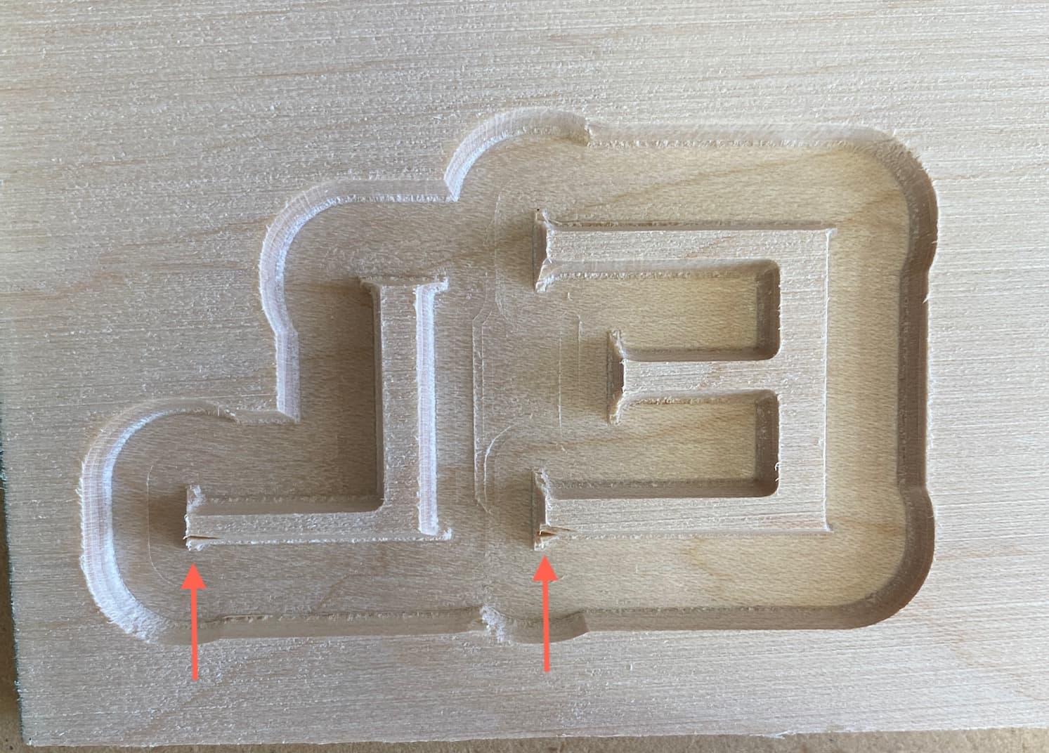
Second attempt came pretty good. Not perfect, but I’m getting there. Used a .02" Bottom Gap this time. (Note: “El” is the first 2 letters of “Elizabeth” - no sense practicing with the whole name). The “E” is 1.5" tall:
The letters are nice and tight in general, but I might have to ditch the serif font for a sans serif since the little tails aren’t perfect. Here’s the male/female parts before gluing:
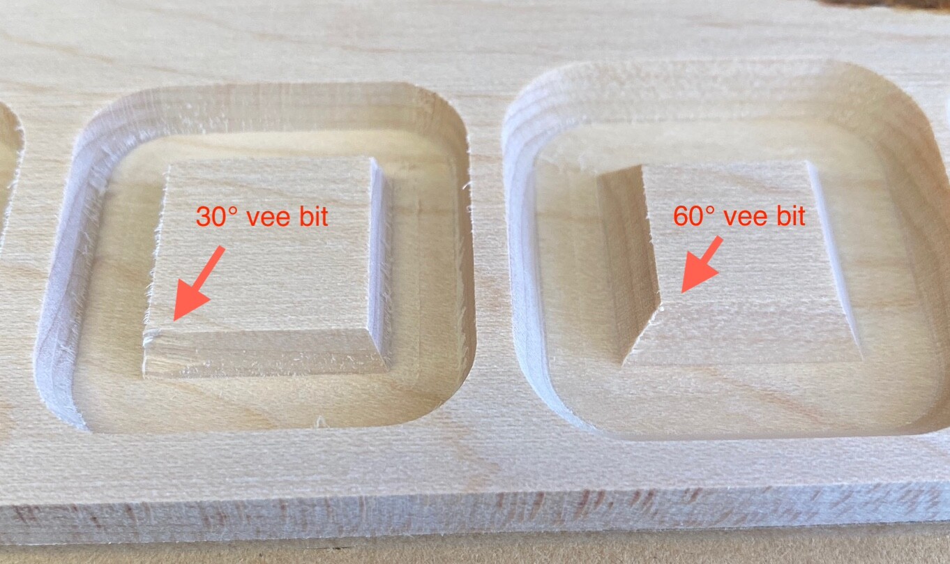
Note the chipping in the following photo. This was an Amana 30 degree Vee bit, .07" DOC. Would a 60 degree Vee bit do better? (Ordered some today from Carbide3D).
The glued maple inlay is flush with the walnut. I expected the maple inlay to sit slightly proud of the walnut. Would it sit higher if I increased the “bottom gap”? (say, from .02" to .03"). Or would increasing the bottom gap only make the unseen glue gap between the maple/walnut bigger?
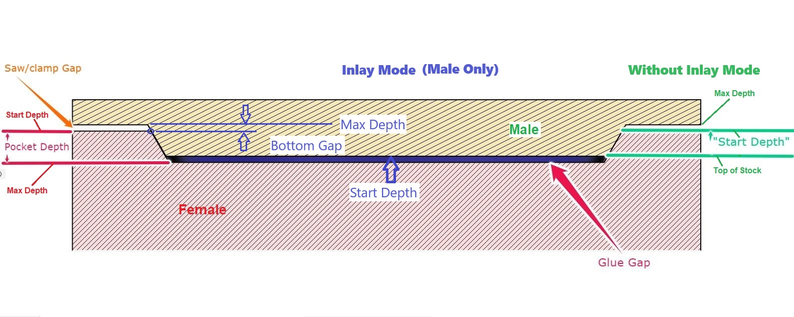
The “Bottom Gap” when cutting the male side refers to the ‘bottom’ as the male is cut, which becomes the top when you flip it over. In this picture, “Bottom Gap” refers to the “Saw Gap”
CC traces the vector being cut at the “Bottom Gap” distance from the bottom of the max depth,
So increasing the Bottom Gap will make the inlay a little bit bigger, so it should sit a little bit higher when assembled.
Honestly, I have had better luck getting perfect fits with inlays using a router inlay kit to make the male and female cuts but then using the CNC machine to make the template in a scrap piece of wood. With a small router, I could cut those letters with the router inlay kit in a few minutes. Of course, there is always some limit with fine detail. The CNC machine though makes it easy to cut the template whereas in the past I did this with a scroll or bandsaw.
That’s how I used to do it, before I owned a CNC. I want to do some intricate work that wouldn’t be possible with an inlay kit and handheld router. I KNOW my CNC is more than capable, once I perfect my settings, cutters and technique.
I’ll answer my own question, as my new 60 vee bits arrived and I did some testing. On the left, slightly used 30° Amana 45771-K vee bit. On the right, brand new Carbide 3D #302 60° vee bit. The 60° is the clear winner on chipout.
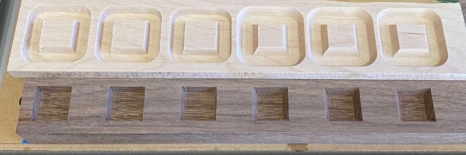
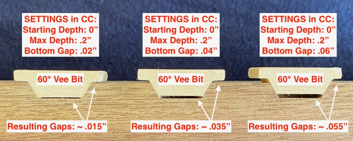
Again, I’ll answer my own question after some methodical quantitative testing, using CC 764 and the Advanced VCarve Inlay feature. I cut three test inlays with a 30° bit, and three test inlays with a 60° bit, changing only the “Bottom Gap” value each time. I tested “Bottom Gap” values of .02", .04", and .06" with each bit. Here are the six test inlays before assembly:
As you increase the “Bottom Gap” value, the inlay rises, and the resulting bottom and top gaps are the same.
With a 30° vee bit, a “Bottom Gap” value of .02" is not enough - The inlay “just” fits, but it doesn’t wedge in for a decidedly tight fit, and results in no actual bottom gap for glue squeeze-out. So…for a 30° vee bit, use a “Bottom Gap” value of .03" or .04".
With a 60° vee bit, a “Bottom Gap” value of .02" seems ideal. The inlay wedges in for a tight fit, and leaves an actual .015" bottom gap for glue squeeze-out.
Thanks so much for posting the results of all your testing. Ive been meaning to play around with the inlay mode for a while now and i suspect you’ve just saved me a lot of time
So? The gap at the bottom is superfluous (and a myth.) It isn’t a functional component of the inlay. If there’s no “glue squeeze-out gap”, the glue will just go somewhere else.
This is the reason for some extra gap at the bottom. It allows for differences in the cut of the inny and outty portions of the inlay. It doesn’t have to be much; just enough so the angled edges of the cut portions tighten up together.
The more flutes the smaller the chipload
You want a good chip load from F&S calculators. So increasing flutes you slow rpm and/or ipm. You want chips not sawdust.