I downloaded the V414 for Mac, it is nice to import JPG and PNG as a component, some files appear to work better than others probably because we need to adjust contrast, etc. It is unfortunately not possible to import the component within another like a pendant.
While I can do it in 413, I can’t seem to import textures in the new version.
Thank you for the Shift click and click and drag hallelujah!
Now when it comes to toolpaths,creating a square around the whole model and selecting that for the vectors let me create a 3d finishing toolpath. I was having trouble with this as I couldn’t select the model or the image
I saved 2 different files on 414 that contain a single texture toolpath in each file. Upon reopening the files it shows a texture toolpath (named texture toolpath 1) with incorrectly saved user inputs and it is not applied to any vectors. Also there is a totally new no offset contour toolpath mislabeled as texture toolpath 1. It is applied to the original vectors that were selected for the texture before saving and closing the file.
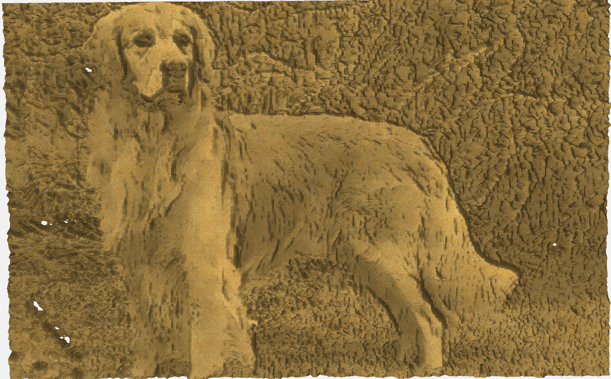
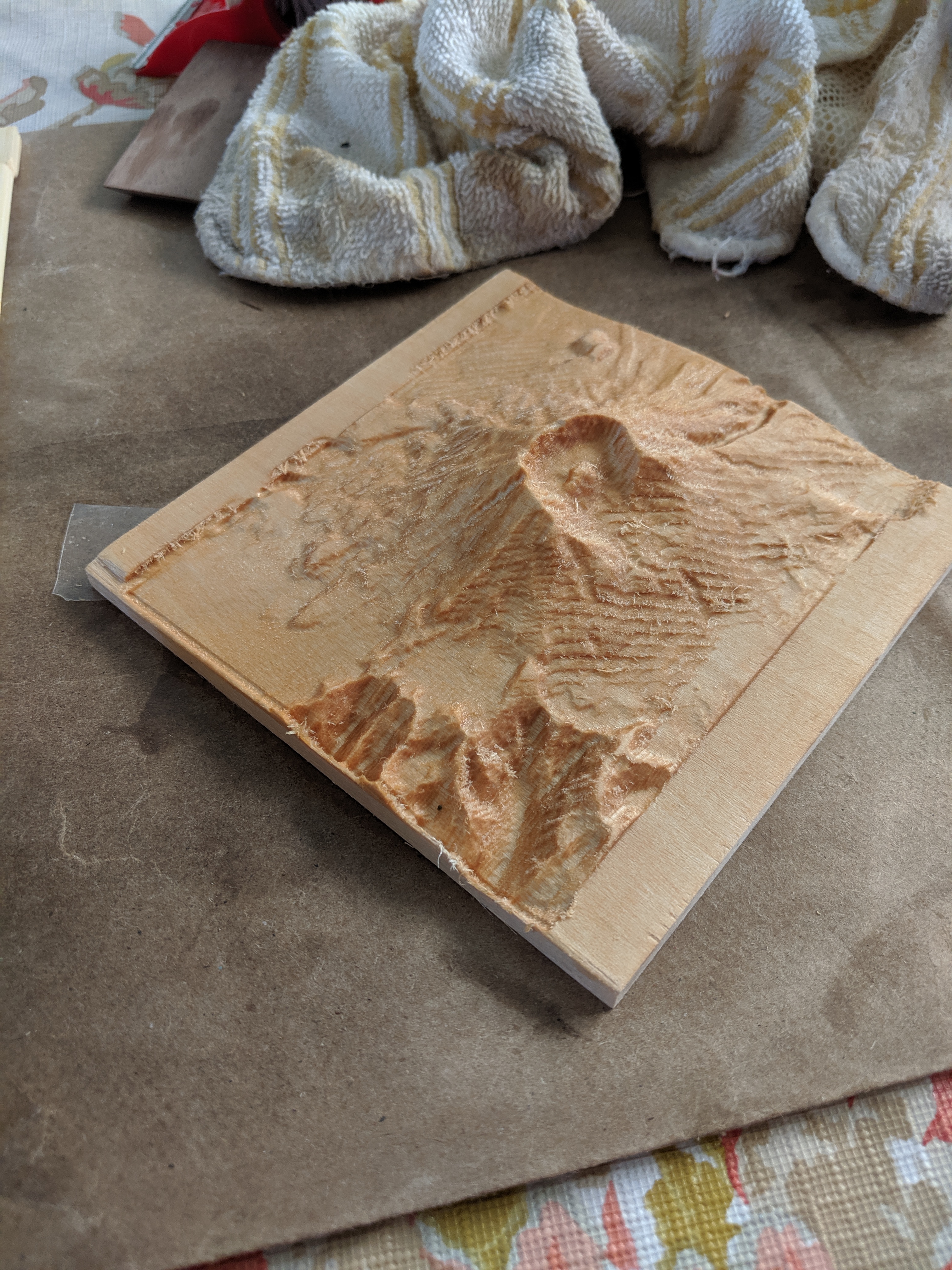
I’m a bit disappointed that the model looks better than the results. I understand that the toolpaths are based on the pretty simple concept that the darker the spot is in the image, the deeper it will cut so dark eyes will be very deep while white skin, for example, will be shallow. There is no 3D image analysis beyond that or stereoscopic processing of the image. I"m not sure if it will be very useful in that form. Of course, this is my first go at it so there may be ways of improving on that but it is limited. I don’t know how the results compare to other systems like Picengrave but maybe with some pre-processing in an image processing software to turn the image into a line drawing, the results could be improved.
works quite nifty, but it would be really nice if there was some sort of “stock-to-leave” you can set for roughing passes
(below was roughed out with a #201 qtr inch endmill and then cleaned up with a 2mm ball nose endmill)
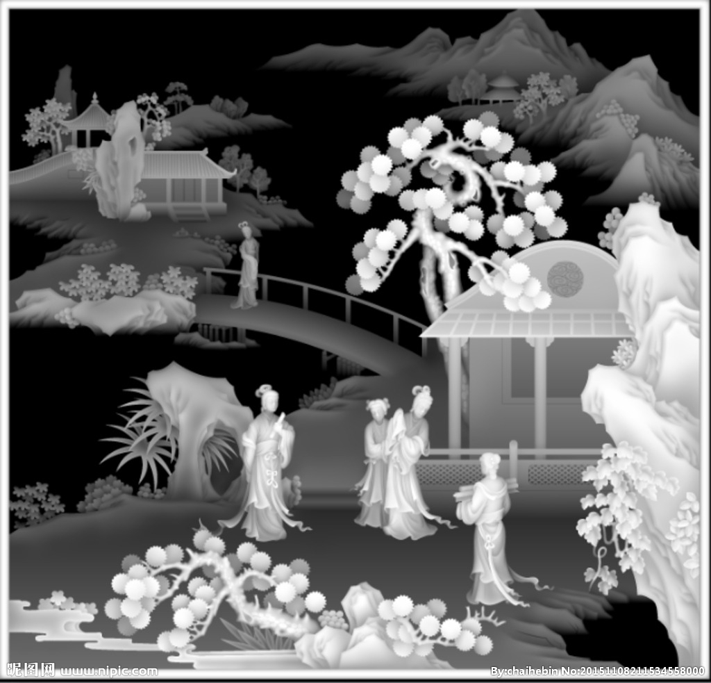
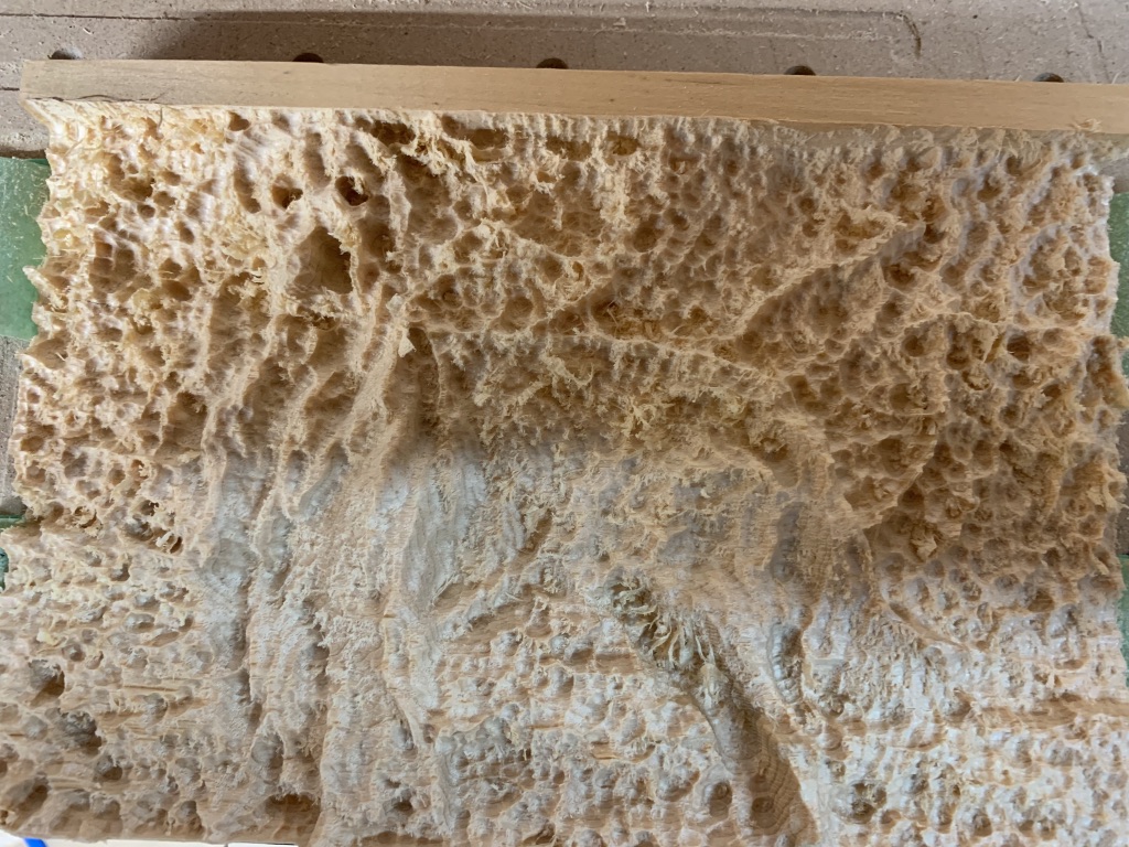
@luc.onthego you essentially created a lithophane on wood. stuart’s image of the asian village was a heightmap not just some random black and white picture. If you try the same thing you did on pine on a thin piece of hdpe (taking in account how deep the image dug into the wood), then you would have a nice lithophane when held up to the light. You could also try to using http://3dp.rocks/lithophane to add some control over your image. Keep in mind lithophane typically only look nice when looking at it straight on with a light source behind it - otherwise it looks like a jagged mess much like your pine version.
If you do try to make a heightmap out of that dog image, then I would suggest removing as much extraneous parts as possible - like the background, etc… just crop those parts out.
Yep I get that, I don’t have any material on hand to create a lithophane. I wanted to see what the CC could do. I wonder if CC will soon be able to import STL to actually carve 3D models.
that would be an awsome feature; there are approximately a billion STLs you can buy on etsy/ebay and they are always a pain to deal with; CCPro with the heightmap shows it’s very close to make these easy
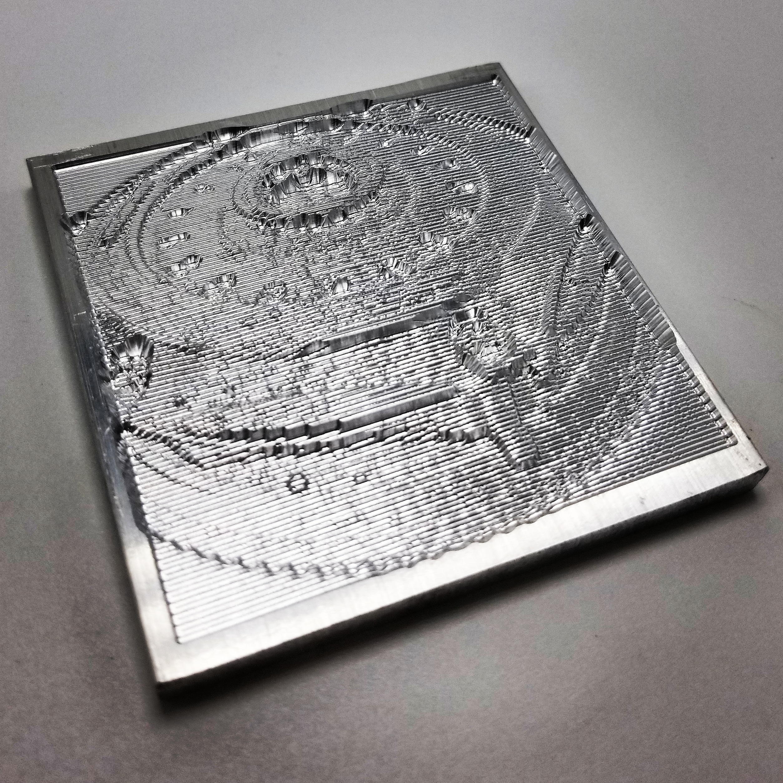
From phone picture of exedy clutch to billet v carved piece, super simple. Also raised Z0 and lowered in 0.020 increments. The v distorted things a bit but increased feed rate was worth it, programmed as 1/32 straight.
Microwave monkey,
I’v been trying to make the same flag and have had problems. Did you use the new version of CC to design this one? If so maybe that is my problem I’m using the older one. Would you mind sharing your cc file to allow me to play around with it.
Optimal for me means shorter. I am amazed that when I generate a tool path for text fit to a round path that the cutter jumps from letter to letter across the circle and basically takes ten times as long to cut the piece as is necessary if it just went to each letter one after the other.
The only way I have found to fix this is to generate multiple tool paths covering small areas which makes programming the cut take way too long. Got sick of it and switched to cut 2D and it does this automatically.
The software is free so I am not complaining - just attempting to respond in a way that is useful.
this seems to be where CC will take objects/paths in a specific order; it seems that it takes the next available object with the highest Y coordinate, and does it in that order.
a more optimal (at least to the human eye) order would be to know where the cutter is and find the closest distance-from-there object.
Bob, you will not be able to open the file 4XX in 316. Please upgrade, you can rename V316 I think you have installed to Carbide Create 316 and download and install the newest version and rename it just after you install so it will not interfere with a newer one in the future. This way you can have a few versions installed at the same time and you will be able to follow along.