Im having problems with 413 loading. I got it downloaded and used it for a few days. Now I cant get it to open.
I have tried removing and reinstalling. Restarting my computer.
I am running Mojave OS 10.14.5
Im having problems with 413 loading. I got it downloaded and used it for a few days. Now I cant get it to open.
I have tried removing and reinstalling. Restarting my computer.
I am running Mojave OS 10.14.5
I see where this is already talked about. let me clear some files
This will definitely show up at some point in the near-ish future. We didn’t have a good way to implement it until we redid a lot of the internals to support the Pro features so it had to wait until now.
Another feature I realized would be useful: When clicking onto an existing component in the Model tab, it would be helpful to see what the shape parameters were used to create the component. I have read the reasoning about the shape parameters not being adjustable after the 3D component is created, which is unfortunate but acceptable, but maybe we could show the values grayed out at least for future reference. That way when I come back to something months later, I do not have to guess on how it was created or guess how someone else created their shared *.C2D file.
I would love a Pro version… just stumbled onto this thread.
My biggest problem with CC, though, is the mac bugs for the cuts screen. It got a tiny bit better with the newest version, but right clicking on cuts is often times a whole inch away form the actual item i’m right clicking.
Now… I’m not terribly worried with a “free” version… and otherwise it does all that i want… but if i’m paying for a “pro” version, i’d expect bugs support and solving of those would be much faster.
Now… as for features i’d love to see… 3d mouse support! I know it’s silly… but for those of us in Fusion 360, a 3d mouse is absolutely essential.
Well it is a problem with your Mac, I use CC on the Mac (Mojave) and it works fine as far as clicking on the items on the screen. Maybe you need to remove CC then remove the preference files in the library and re-install fresh.
Usually such problems (clicks being offset) is caused by a disconnect in high-DPI screen scaling — please let us know what graphics card and screen size you are running at and what screen scaling (if any) you are using to support@carbide3d.com and we’ll try to have a developer look into it.
que este también en español. y hacer más vídeos desde nivel 0 para aquellos que recién comenzamos y que no tengas que ser ingeniero de la nasa para utilizar
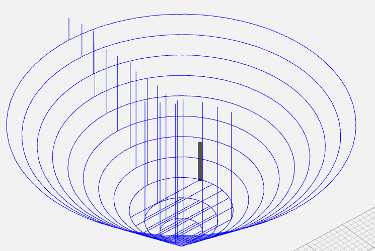
I figured I’d play around for another couple minutes in Carbide Create Pro to check out the 3D roughing. I whipped up something extremely basic and then looked at the G-code. I went into the experiment thinking that I really want to be able to set the stepdown, and while that may be the case, I actually discovered that the G-code was really screwy.
I imagine the 3D roughing is intended to be like cutting an inside profile at the first stepdown, then pocketing inside that, then stepping down to the next inside profile, then pocketing that, and so on. The G-code does seem to include all the appropriate cutting, but the sequencing is not cromulent. In the image above, the G-code is actually cutting all the inside profiles one after another all the way down all the steps, and then it’s going back and pocketing inside each layer starting at the bottom. This is obviously unintended behavior.
Here’s my example data: Bump.zip (176.6 KB)
Being a developer, I treasure reports that include excessively fine-grained detail about exactly how to replicate an issue, so paying it forward (and so anyone else here can see if they see the same thing), here’s my step-by-step example as precise and clean as I could make it:
Model tab, click the Import Component icon and choose “Bump.png” (from the attached zip)Import Parameters:
Height to 38mmXY Scale untouched (0.455)Invert uncheckedComponent Parameters:
Add
Done
Toolpath tab, click the 3D Rough buttonEdit buttonTool, select #202 - 0.250 in Ball
Set speeds automatically checkedSave GCode button(Following those steps gave me differently-bad sequencing than I got with my example C2D file in the zip and shown in the preview above, but it is functionally equivalent for the purposes of debugging. Both my original example and what I got following the precise replication instructions resulted in “impossible” G-code.)
We just finished adding the depth-per-pass to roughing so that’ll be in the next release.
We can duplicate this behavior here so we’ll get that fixed, hopefully today.
We had to take a short break from the CC development to build the licensing portal so we can test that out before the launch. Hopefully we’ll have a release in the next few days with a bunch of fixes.
Haven’t seen mention of that before. More info?
We need something to manage the subscriptions and perpetual licenses for CC Pro so this will be the central place to look up your credentials. We don’t want to make it happen thru the app because a lot of users don’t have Internet in their shops so it needs to be a standalone site.
I forgot to thank you for such a clear bug report. Others (clearly not you) might be surprised how much time we spend just trying to figure out what the complaint actually is before we ever get to the point of trying to duplicate it.
We’ve got it fixed so it’ll be in the next release.
We just uploaded 416 to: https://carbide3d.com/carbidecreate/unstable/
416
This build will require a license code or file. Create an account at https://launch.carbide3d.com then click the Create Trial button.
You can either cut and paste the info into CC under Help->Register or download the license file and load it in the same window.
Rob tu nos vas a cobrar por usar el Pro así te hayamos comprado un Shapeoko ?.
should this also fix the issue where 2D pockets leave little ridges ?
Sorry I haven’t posted this yet,
CC 414 Unstable
7-18-2019
Resizing SVG Error
Repeated 5 Times-non responding error.
Open SVG file,
Go to resize, clicking outside corner spanning to change size. If you go outside of 45deg angle the image distorts, disappears and causes system to go un-responsive.
Exiting re-size and doing ctrl z does not undo the issue.
EDIT***This seems to now be fixed. SO Nvrmnd.
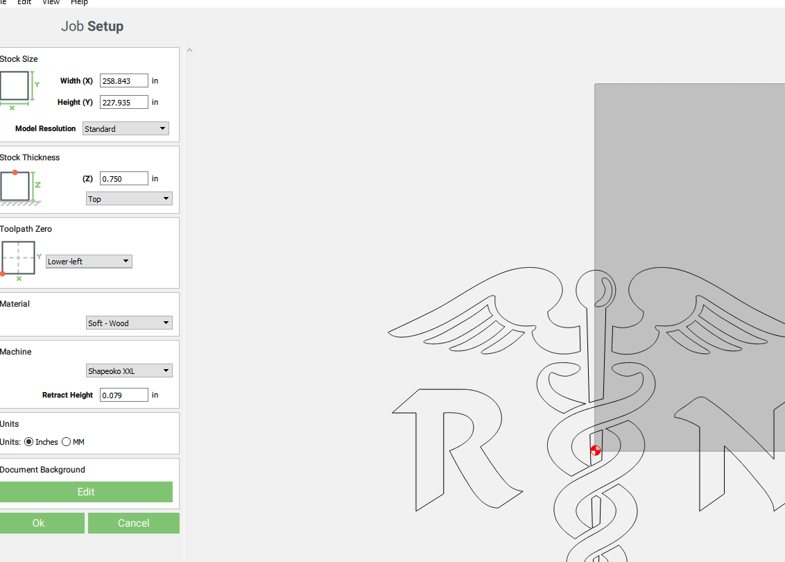
Stock Size Error when importing DXF file
Existing stock size setting changed during DXF import.
Stock size is exaggerated when importing DXF file. Was increased to 258in x 227in. No error on stock size occurred.
When going back into settings for stock the numbers are saved to increased size, clicking done sets off error of stock being too big for machine, but canceling leaves the exaggerated stock size output.
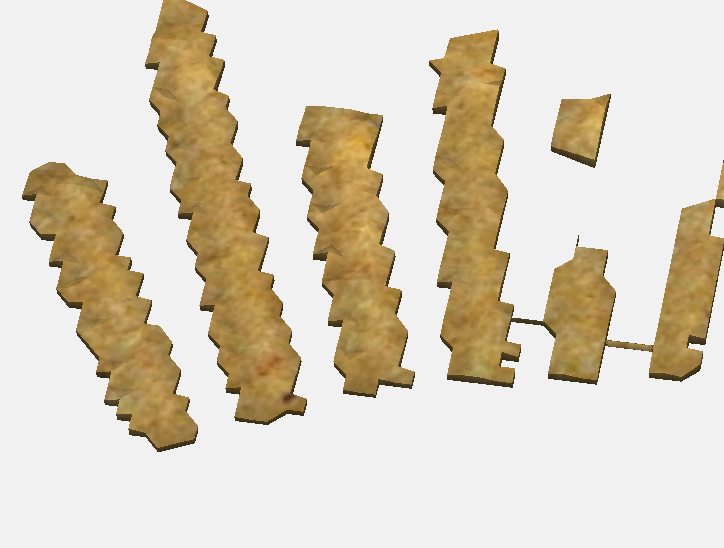
CC 416 Unstable 7/25/2019
Now 3d modeling looks worse than it did in first Pro Beta release. I used the same SVG and the same technique. Set to Very High resolution. and this was the result in the lines above Eagles Head. I didn’t go any further.
EDIT* I did this in CC 410 Pro- Enabled and these were much cleaner.
Thanks, that makes sense. ![]()
417 is up at: https://carbide3d.com/carbidecreate/unstable/
417
Nope- that’s likely due to the stepover being > 50% of the tool diameter and is a common problem in contour offset toolpaths. It’s not a simple thing to change so it would have to be handled in the future or with the option to use a parallel pocket algorithm.
The model has a fixed number of points to cover the whole document so if you have a tiny section of it with high detail, there are not going to be many points in that area. It is analogous to reducing the dimensions of an image to 10% of its original size. The detail would be removed and it would look blocky/blurry. Would should always make the size of the document fit the area you need to cover so the points are all allocated to the area you need.
At some point we’ll put out a video to make this more clear.
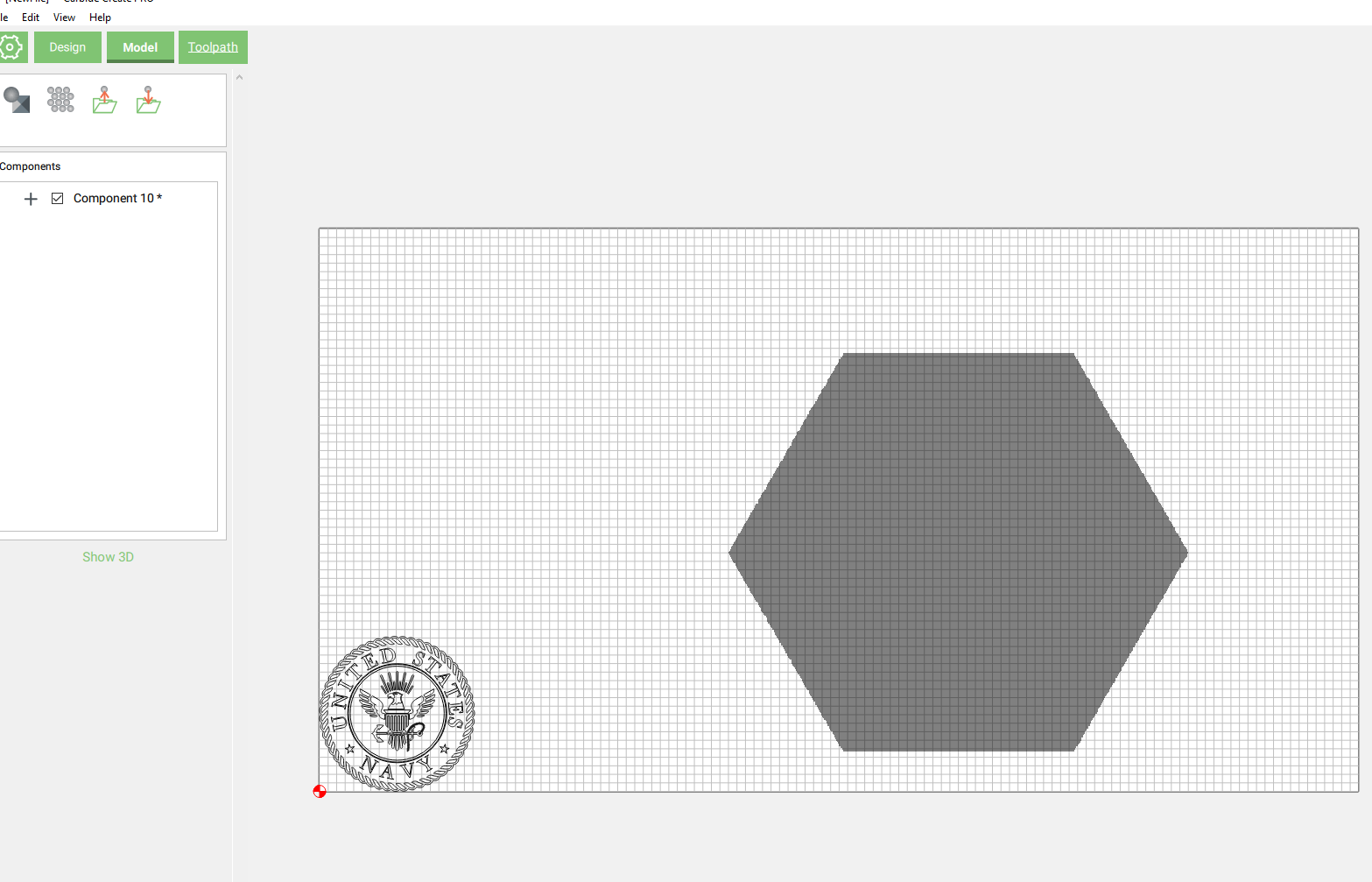
So when you create a model/component and want to just abandon and open a new SVG, the model/component is not erased and is left. No matter what SVG you select the component remains and the design space is only reset upon selecting a .c2d file or by file, new.
Upon selecting open and opening an new SVG file the work space should reset to blank.
This was documented above under 416 second bullet down.