yup fix confirmed; thanks for the quick fix
1 Like
429 is up at https://carbide3d.com/carbidecreate/unstable/
- (NEW) Optimized internals to make dragging many many objects more efficient.
- (FIX) More aggressively try to close SVG paths on open.
2 Likes
CC429: texture tool paths failing to load properly when reopening a file created with CC429. Texture tool path and user inputs are saved properly, but upon reopening the file the tool path displays “Empty Toolpath” in place of the estimated time. I haven’t tried to open a file created by an older version of CC yet to see how it reacts.
edit: all it takes is editing the tool path to get it to load the estimated time again
edit 2: having some trouble with the simulation not loading. It loads for a minute and then displays a blank window. No problem hiding the simulation, doesn’t cause the program to hiccup or close.
1 Like
Can you post a broken file?
2 Likes
WH40K_IW_Insignia.c2d (443.0 KB)
Just noticed if you go so far as to edit the tool under the texture toolpath, it will reset the feed and plunge to defaults.
Simulation will show toolpaths and rapids if selected, but the “material” does not render.
Edit: No simulation rendering issues when I disable the texture tool path. Makes me think it is a graphics issue on my end as I am using the built in gpu on my Intel Nuci5.
Edit2: Renders with texture fine on 417
1 Like
I think we found a combination of two things- the texture toolpath wasn’t loading a time estimate and the texture caused too many triangles for some video cards so it may not show a simulation. We’ll get a new build out tomorrow.
2 Likes
Just posted 430 to https://carbide3d.com/carbidecreate/unstable/
- (FIX) Texture toolpath time estimates
- (FIX) Modified simulation resolution
2 Likes
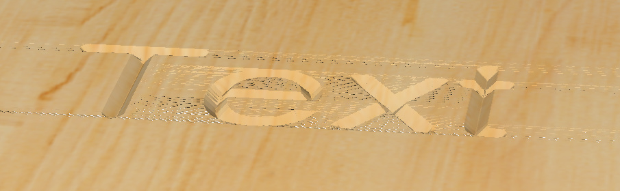
CC 430 - certainly a step back for me. Here is just a new document with a simple “Text” v-carve. It looks awful and has many incorrect artifacts - notice the horizontal lines…

Edit - It only happens with v-carves. I checked a few older documents and all endmill toolpaths etc seem to render fine but all v-carves are horrible
I am using an AMD Radeon R7 200 Series with the latest drivers - which has always been more powerful than I need.
I also notice that I used the default settings for “Text” and it actually placed it somewhere way off the workpiece to the top right - took a while to find it until I zoomed out…
test.c2d (42.9 KB)
1 Like
The text object when added has always been placed up and to the right of the bottom left of the stock — only an issue when working on really small stock sizes — resetting the view brings it into view.
Ahh yes - Last time I used CC I had an unusually small sized stock - which it remembered for this test,
I also noticed several CC versions ago that the simulation is “hollow” - i.e if you rotate to to see the underside there is no bottom surface rendered.- the workpiece is “hollow” This explains the many white speckles in the screenshot - it is the white background bleeding through the infinitely thin top surface rendering.
431 is up at https://carbide3d.com/carbidecreate/unstable/ with a change to the simulation resolution
2 Likes
thanks @robgrz - better but still not as good as it used to be…
We’re trying to find the happy medium of good-but-not-melting-the-gpu. We’ll keep tweaking.
2 Likes
i understand - its always a compromise.
i suspect if you render the bottom surface then the problem might not be so obvious - worth a try?
2 Likes
The most important feature I wish to be added to the Free Carbide Create is the ability to manipulate text and Set Text to Path. Also, Cut/copy & paste. I know you can do this with the offset command, but a plain cut/copy & paste would be nice. One last wish is Layers. I think the ability to work on different layers in a design software is remarkably important.
Also, how much are you planning on the Pro price tag? The 2nd or 3rd main reasons I decided to buy A Shapeoko and not X-Carve was the cost of the software and the software being stand-alone and doesn’t require internet connection.
The main reason I went with Carbide3D VS Inventable was Customer Service and the help the community members get from a group of seriously devoted people, or better, name the person who influenced my decision, for sure it was Mr. Adams, William. I owned and operated a mid. size computer business for over 20 years. If I had someone like Mr. Adams in my business, I think I would of still be in business.
Back to the subject, I wouldn’t mind paying for a pro version of Carbide Create as long as it has a reasonable price tag.
3 Likes
CC 431: Create a 3d finish tool path for multiple objects(all the same shape and getting parameters from one “Component” created under the modeling tab). Select “ok” saving the path. Check simulation. Figure out changes. Double click the recently created and saved 3d finish path to edit. Upon deselecting some of the objects to leave them out of the tool path, CC431 does not respond and continues to select them as being cut. Current work around is deleting the 3d finish tool path and creating a new one selecting only the parts of the “component” I want to cut out. Stumbled upon while prototyping reliefs where test cuts and editing are constant.
1 Like
Text on a curve is coming. We’ve got most of the internal change made, we just need to dedicate a solid block of time to create the rest of the user interface.
I agree completely which is why I’ve been shocked that it’s hardly been requested at all. I think that layers will make it in there at some point. Again, the user interface is the toughest part.
$120 per year or $360 for a perpetual license with a year of updates. We’re trying to make sure that we keep everyone happy- the subscription folks and the never-subscription people as well.
I think our support people are the best out there so it’s good to hear that customers have enjoyed their interactions with them. Thanks for the feedback.
The 3D toolpaths in CC define the toolpath boundary by the selected vectors (like the 2D toolpaths), not by selecting the model components. Did you change the vectors used to define the toolpaths?
2 Likes
Rob,
The way I understand it is that the 3d finish toolpath pulls parameters for cutting from the model in terms of cut depth and shape, is that correct? I was just trying to clarify that the objects selected to cut all came from one “Component” created to set their depths and such, not selecting multiple vectors that have their parameters set by different components. I apologize for any confusion. To clarify, here is a way to repeat my issue: I have a piece of stock that is 12 inches wide by 12 inches tall, and 1 inch thick. I set appropriate parameters under job setup for my stock size. Under the design tab I draw a vector around the whole work area, select it, and under the model tab create a component equal to the depth of my stock. I would like to make 3 circular indentations in the stock, so i draw 3 circular vectors under the design tab, go to the model tab, select the 3 circles and create a subtracted component. I now have 3 circular “reliefs” in my model. I go under toolpath tab, and select the 3 circular vectors(not the outer vector that i used to create the model for the material) and create a 3d finish toolpath, set stepover/feed/etc and click ok, thus creating the toolpath for all 3 cirular vectors. Check simulation and decide I want to test cut only 1 of the 3 circular vectors. So i go to edit the 3d finish toolpath I just created and it won’t allow me to deselect the other 2 circular vectors. The cut paths(blue lines) for those deselected vectors persist after editing as does the longer estimated cut time. I added a 4th circular vector with appropriate component under the modeling tab and CC will allow me to add that vector to the 3d toolpath, but again wont let me deselect it once “saved” to the toolpath initially.
edit: realized i didnt answer your question. I did not change the size or position of any vectors in between setting the initial 3d finish path and attempting to edit it.
edit 2: i deselected the extra vectors and saved the toolpath and closed out of CC. reopened the file to find that it DID change the 3d finish path, it just didnt display properly without closing and reopening
edit 3: Sent gcode for an edited 3d toolpath(3 previously selected circles down to 1) that wasnt displaying properly directly to CM and found that without saving and reopening the file, it will continue to send the code to cut all 3.
edit 4: selecting any “new” vector to include in the 3d tool path, and simultaneously deselecting the 2 circular vectors i want to remove from the 3d toolpath seems to make it work. But then I am stuck with trying to remove the “new” vector added to the 3d toolpath before sending directly to CM. Editing the toolpath and deselecting all vectors and clicking ok, then editing the toolpath again and selecting only 1 circle seems to work and make the extra cut paths disappear.
1 Like
Will there be a titling option added?
Tiling would be Carbon Create that would cut the project in pieces, Carbon Motion is the sender where you would load each file to be cut unless you have something else in mind like prompting you through the process but CM would need to be aware of the upcoming toolpaths like I suggested above where you load the sequence of toolpaths to be cut for a given project.