I should probably confess that there was a fair bit of back-and-forth when I was first testing this — took me a while to feel out how the feature worked and what its limitations were — for now, folks should post files which they expect to work here, along w/ a description of what they were expecting and we’ll have to see what should be done.
For now, smaller tools seem to work better, so if that’s an option, try the next size down when you don’t get a toolpath.
“t” will use the project thickness and update anytime it changes…
!!! Is it Christmas? No one told me it was Christmas.
“G-code is now stored in the C2D file, not in an external G-code file.”
Oddly I think I have the same reaction you guys did. “You can’t do that… I have no idea why… but… ummm, okay.” Typically I have kept my design files on the local machine and saved my gCode to the network drive (So I can get to it in the garage). It might take some getting used to, but might actually be better in the long run.
A simple solution was to set the spindle RPM to 1, my small (only size I currently have room for) non-C3D router doesn’t turn, hum, etc. at this speed. Grbl also has a firmware setting ($31) to specify minimum spindle speed, that (unnecessarily in this case) set to the lowest speed where the spindle would start (not continue) turning.
There’s one caveat, if you have a non-PWM capable spindle, such as a router controlled by an SSR or mechanical relay, and set the maximum spindle speed ($30) to 1 so your PWM signal is either completely off, or completely on, this won’t work. In this case setting both $30 and $31 to, say, 2 might work but I haven’t tried that.
My purchased before the MC Etcher was available spring loaded drag bit likes about 5mm of compression for hard(er) aluminum, I use a fairly low plunge rate to protect the tip (perhaps unnecessarily)and feed rate retracts were painful to watch. Md8n’s gcodeclean utility on github has an (on by default) option to convert G1 retracts to G0 rapids, which made a considerable speed difference. The same utility will also convert short line segments to arcs, this can greatly reduce gcode file size and provide a modest runtime decrease by reducing the traffic on the usb to serial port. I leave the philosophical discussion of arcs vs line segments for elsewhere but haven’t seen any detrimental effects across numerous projects.
One issue with this is that most drag bits are less than perfectly centered. As the bit rotates, it can move the line off the expected center. I’ve witnessed this. Additionally, although maybe this has changed in recent versions, there was a minimum RPM allowable.
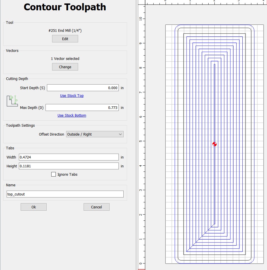
I have updated to 710 and on 708 I had a problem figuring out how to add tabs. I see the place to put your measurements for the tabs but I cannot get tabs to appear while clicking on the tool path. In V6 CC you went in to the “Edit Tabs” and placed your tabs. See picture below
In the new V7 version 710 and in 708 I cant figure out how to place tabs. There is a place for the measurements of your tabs but cannot get tabs to appear. How do you get tabs on the project?
One additional question. The tool path lets you set your tab width and height. I usually do not use the default ones C3d sets. So if I forget to change the default sizes are the edits made in the tool path after tabs are added and they change or do you have to remove the tabs in the size you do not want and go back to the tool path and set what size you want and go back to design and add the tabs in the size you want.
@gdon_2003 Guy - It looks like the position of the tabs is a design element, but the size of the tabs belong to the toolpath. So it looks to me like you have to adjust them in the toolpath. Seems like that’s the only place.
That’s an interesting point…couldn’t the size of your tab (the length, not so much the depth) impact the design layout in certain circumstances?
So with some amount of support for expressions, how far away are we from some amount of user defined parameterization? Also, I see ‘t’ is already defined. Are there any other variables that can be referenced?
I started using CC with my first CNC, a small Genmitsu machine. Because I learned CC, it was a no-brainer to move to my current Shapeoko 3XL.
Being able to save a G Code file and use it on the Genmitsu, and then the SO3 was perfect for me as a new CNC’er. The courtesy of offering CC for a non-customer, was a deciding factor in moving up to the SO3… only took about 3 months!
With a design PC in my office and the CNC in the garage (connected by my network) I was able to design in one place, and “make” in another…
This inability to not save G code files really feels to me like C3D is penalizing Shapeoko customers to keep out non-customers… disappointing!
I feel that the best solution would be an offline software program to pull a G Code file out of a V7 .c2d file… easy, effective, and limited to C3D hardware customer only, via serial number or some other non-online implementation.
My apologies, it’s not in the Move palette — it should work to just select something and then move it using the arrow keys, so icon necessary — it’s working here in 652 and 710 on Windows (will test on my MacBook when I get a chance).