We’re releasing our first public build of Carbide Create V7 today with a lot of big changes. The download can be found at: Download Carbide Create V8 for those that want to try it out. It includes major internal changes but our testing has shown it to be stable so we’re ready to share. (That said, we’ve changed the file format to support all of the changes we’ve made so please give it an initial test on a non-critical project.)
And now, on to the changes…
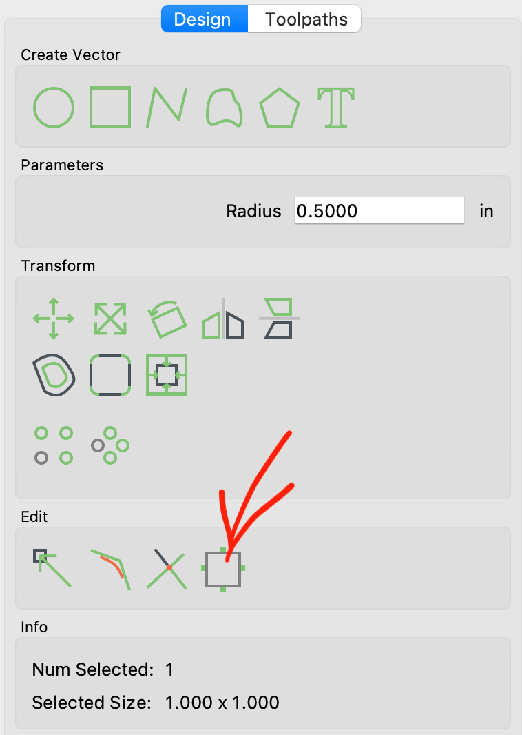
Tabs are now a part of the vectors, not contour toolpaths.
We added a new tab command to add tabs to a vector. If you copy the vector, you copy the tabs too. This should be helpful for users that are doing production work where they may want to fine-tune the machining of a single item and then copy and paste an array of them for full production.
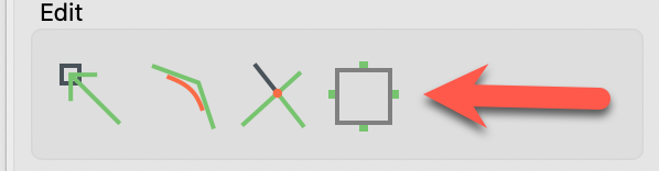
Look for the new command here:
Text alignment
Text objects now hold an alignment value of Left/Center/Right. For a single line of text that never changes, this doesn’t matter at all. If you have one or more lines of text that will change then this will be really helpful because the text will keep its alignment on the document after the text changes.
We also added a bit of code to update the text preview automatically as the parameters change. We may have to tweak this a little if we get feedback that some machines are bogging down. (It shouldn’t, we were pretty conservative about how often we update.)
Text on an arc
Text can now be laid out on an arc, with the text on the top or bottom of the arc. In the text command, you can set the arc by dragging the center point or the reference point of the arc to get the alignment and radius that you want. If you hold shift while dragging, it’ll move both the center and the reference point at the same time.
When text is on an arc, we use the middle of the text as the baseline so that text on the top and bottom of the arc appear to line up. There’s no reliable “middle” of a font so we determine that by taking half of the height of a “T” as the midpoint. That may or may not be perfect, depending on your particular font, but it seems to get you in the ballpark with our testing.
Expressions in numerical fields
In almost every numerical field we now allow math expressions. Type in your expression and then hit “=” to evaluate it and input the answer. For instance:
- “1 in=” will change the value to 1 or 25.4, depending on the document units.
- “25.4mm=” will do the same thing, but in metric.
- “25/2=” will update to 12.5 (which is convenient for people who want to convert a diameter to a radius, or vise-versa)
These have been useful to us so far but the real win is that toolpath depths, both the start depth and the max depth, can hold an expression and update anytime the project thickness changes. For instance:
- “t” will use the project thickness and update anytime it changes.
- “t=” will immediately evaluate as the project thickness but not update on changes.
- “t/2” will cut to half of the project thickness and update anytime it changes.
- “t+.01in” will cut .01in past the bottom of the stock and update anytime it changes.
As you go through the change log, you’ll see a lot of notes about bugs in the expression code. This was a deep UI change and we think we’ve got it working well but be sure to let us know if you find anything funky.
Once we get this build tested we’re thinking about adding 3-4 other depth variables so that you can have a few intermediate depths values that can update toolpaths. We’ll see if that turns out to be a good idea.
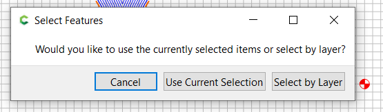
Toolpaths can be linked to layers
Toolpaths can now link to a layer instead of individual vectors. If a toolpath is linked to a vector, it will recalculate any time the contents of that layer change.
On the surface, this seems like a convenience feature, but we think it’s much more. When combined with the depth expressions above, it allows you to make template files that contain known-good machining precesses where you only have to add vectors to the correct layer and you’re good to go. There will be no need to tweak toolpaths.
For instance, if you have a wooden sign file you might have:
- Engraving layer linked to a V-carve toolpath
- Pocket layer linked to a pocket toolpath with the depth set to “t/2”
- Outline layer linked to a contour toolpath with the depth set to “t+.01in”
All you’d need to do when starting a new job is load the file and add vectors to the correct layers. If you change the thickness of the stock, the toolpaths will update automatically.
ANGLE rendering is now the default on Windows
We’ve found the ANGLE rendering option to work well on Windows so we’re making that the default now. You should not notice any changes from this but it’s worth noting in case anything comes up. (I wish I could share some of the customer interactions that triggered this change.)
G-code is now held in the C2D file
G-code is now stored in the C2D file, not in an external G-code file. This has been a request for a while but it had to wait for a new file format to make it work and it brings a couple of benefits:
- Only one file is required for a project so the G-code and the project should not go “out of sync”.
- Because the G-code and the project are stored together, you can always load it back into CC to edit something and then run it again.
The other thing this fixes is a growing support problem. We’ve been dealing with a lot of users who buy other (non-Carbide 3D) machines and then use CC. While it’s great that people are using CC, it’s bad because they’re buying from companies that provide little-to-no support so they end up trying to get us to help them use their machines and it’s not always clear that they don’t own one of our machines until there have been a number of emails back and forth, or a phone/video call. This is now getting in the way of us providing support to Carbide 3D customers so it needs to end.
We’ll be honest here, we also deferred this change because it felt unnatural to have the toolpaths in the design file. We’re not quite sure why it was unnatural other than, “because that’s not how it’s done”. After using it for a few weeks, we’ve become big fans of having a single file for everything and we don’t think we’d ever want to go back.
When you click the “Save Toolpath” button in CC V7 you’ll get a popup to save them in the current file or create a new C2D file. The “new C2D file” option will not update the current filename for future saves, which makes it a good way to output the currently-enabled toolpaths, but keep working in the original file.
The new C2D file also compresses most of the data so there’s generally no space penalty for putting the G-code and the design in a single file.
You’ll need to download Carbide Motion 565 or later, which supports the new C2D file format. 565 also adds a button to save the G-code to an external file if you want to review or edit it outside of CM.
Carbide Create Pro still has the option to save G-code to a standard file if that’s what you’re looking for.
We’ve also been testing this web-based G-code extractor for users that need to get their G-code out without Carbide Motion: Extract GCode from Carbide Create V7 . It’s not gated by a customer list yet, you only need a login for the community site, so feel free to give it a shot.
Rest Machining (PRO)
V7 adds a Rest Machining option for pockets that allows you to only machine the areas left behind by another pocket operation with a larger cutter.
Keyhole Toolpath
We also added a very basic toolpath to create Keyholes without amnually editing G-code, which is what a lot of users have done up to now.
Measure Command
V7 adds a Measure command to make it easier to determine the distance and angle between two points. It’s a simple command but it’s been high on the request list for a while.
Some users wanted to use the Measure command as a way to construct geometry, which is not really the intended use. Instead, we added segment length and angle information to the Polyline command that should make it a lot easier to create construction geometry that you can snap other object to.
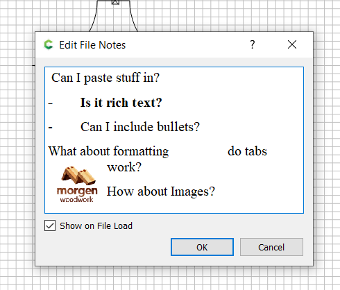
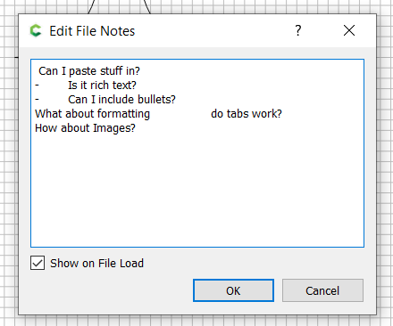
Notes command
After several user requests, we’ve added a “Notes” command so that you can add notes to your future self. You might want to hold change revisions, information about the customer or workholding, or where you sourced material for the project. It’s free-form and it’s totally up to you.
Other changes
We’ve made a lot of other smaller changes to make the program more responsive based on test files from users. Honestly, these are some of our favorite changes to make because these test files often show error in our thinking up to this point about how the program should be architected.
We’ve heard a number of comments like, “I don’t know what you changed here but it feels a lot faster”, which is not scientific, but it’s nice to hear.
Going forward
The changes above represent all of the deep changes we plan to make in CC7 so they were the minimum we needed to get done for the first release. The rest of the todo-list items are more user interface changes and changes to commands that don’t span the whole program. We’d like to get all the feedback we can soon so we feel comfortable getting V7 released. Once we hit that milestone, we can get more features added.
We’d love to hear how CC V7 works for you, whether the feedback is good, bad, or indifferent. Please reply in this thread so we can keep everything together and not confuse others who are not running V7 with V7-specific problems or comments.