The file is too big (>4MB). Any way to upload directly to you?
Put it on a network drive such as Dropbox or Google Drive and mail the link to us?
yep…
I bought the file from Minimega, who would like to use it please be so fair to pay that guy.
It would be better to send the link as a PM or in an e-mail to support — I’ve removed it out of consideration of copyright and for the sake of the person selling it.
Please re-send the link privately/securely, and make sure that it will be accessible by the recipient (set permissions to “Anyone with the link” or something along those lines).
Agree: that is the right way to do. Will send it to support. (how does PM work? It appears to me like an open discussion when I click on your name?)
The interface is the same, but when you click on a person’s name and use the “Message” button it will be limited to the folks specified.
Thanks to Will I now have the skills to do the contours for the STL when needed.Great support and thanks so much
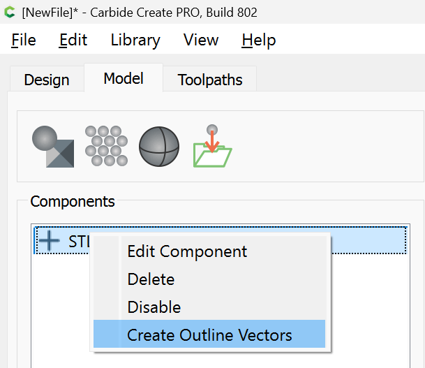
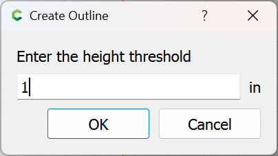
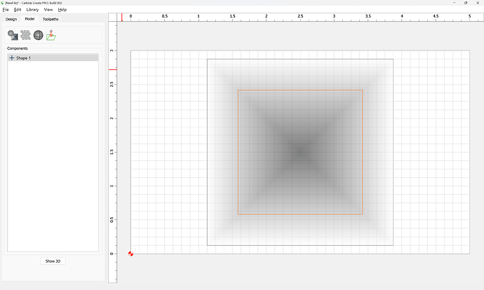
For folks who are confused by that message, it relates to a walk-through done via support, on how to use the new right-click menu entry for tracing the outline of a component of a 3D model.
Could this be conceivably used to create outlines of an STL model at various depths/protrusions from the rendering plane to manually create waterfall toolpaths?
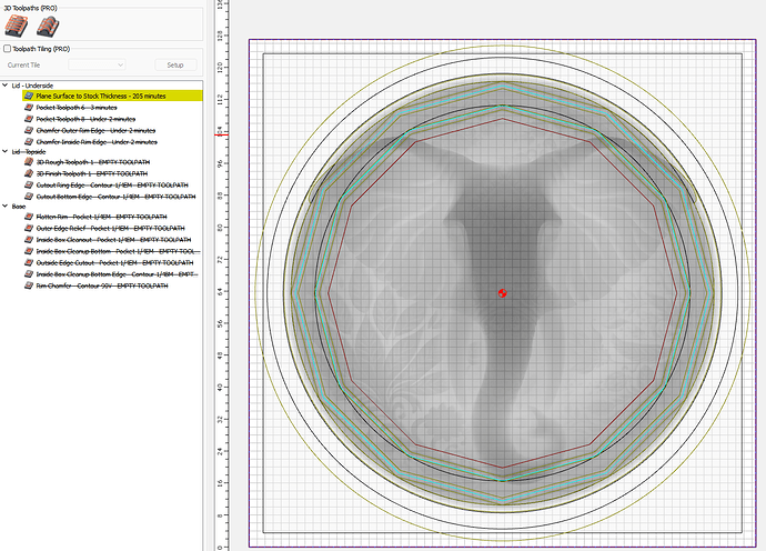
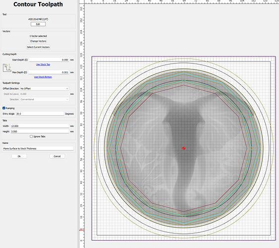
So looks like I threw CC v8 a non-typical toolpath setup & it spit out a non-sensical result.
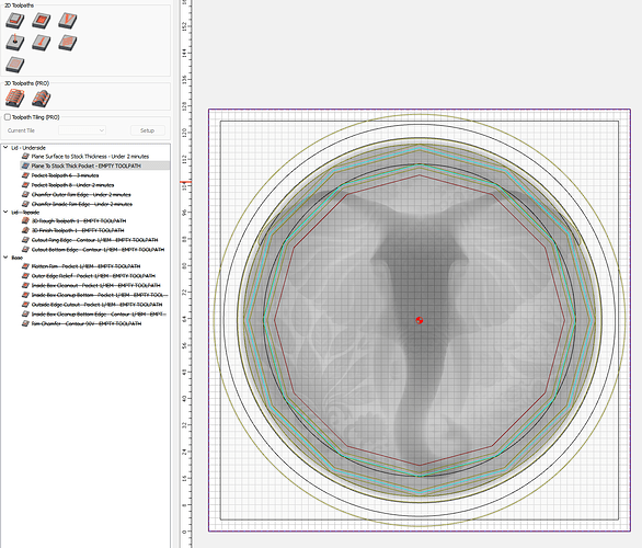
The toolpath color code would indicate that it is Empty, but yet it came up with a ridiculously long toolpath time to go around in a 127x127mm square.
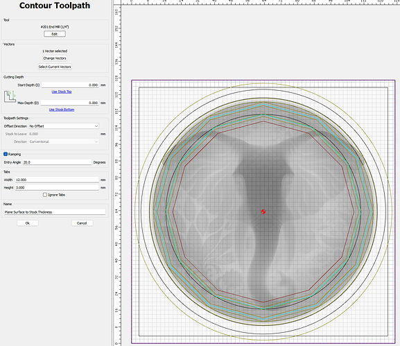
My stock thickness is a little more than what I had specficied in the project settings, so I decided I would try to just create a contour/pocket square that would plane down the stock thickness to spec.
So I’m just trying to get CC to create a toolpath at the top of the Stock height as the Z zero is set for the bottom. I would think it would create a toolpath which just results in zero removal of material within the proram.
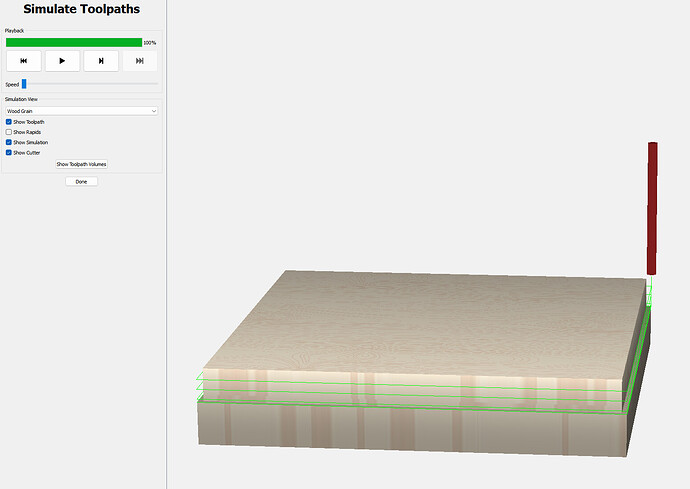
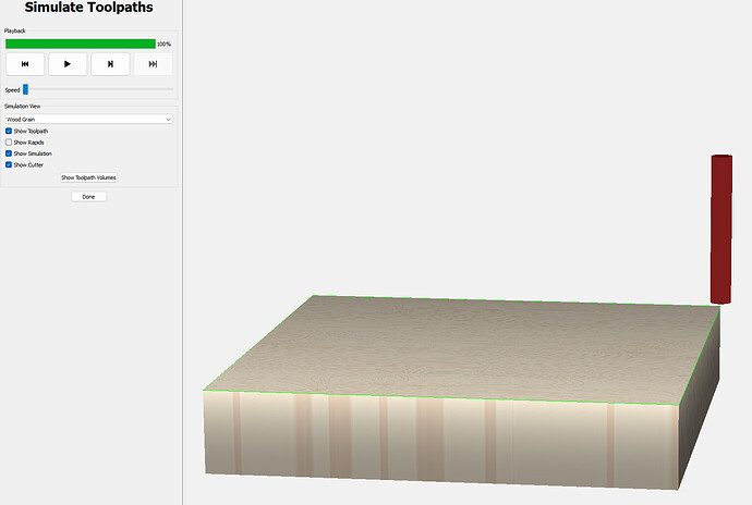
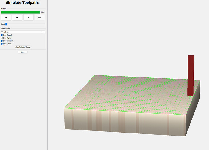
But then upon simulating the cut…
It appears it decided to go through nearly half the stock thickness at a DOC way larger than the 1.50mm I used in the tool setup.
So I think the whole trying to cut at 0mm height down to 0mm resulted in some kind of divide by zero & go crazy!
Changing the target Depth to 0.001mm seemed to make it happy.
Curiously, doing the same 0-to-0mm Start-to-Max depth in the Pocket toolpath generator results in just an empty toolpath - though it doesn’t get flagged with the yellow highlight color.
Again, changing the Max Depth parameter to 0.001mm allows it to work & generate a toolpath.
Anyway, just figured I’d document this behavior even though it’s quite a non-typical user case.
Any consideration to starting a subcategory on the forum under Software for the Beta posts? These threads that become huge are difficult to digest (matching up the question/answer).
I think the time to cut the text in this file is WAAY too long. 48 minutes. I have not been able to reduce it.
???
Neighbor.c2d (384 KB)
Try changing your Retract height to just a tenth of an inch above the stock height instead of 1/2in.
That cut it drastically, about 1/2. I hadn’t noticed that had defaulted in the Beta download.
Thanks,
I am surprised at the revelation that an STL import is converted to an image based model.
That is disappointing.
For folks who want a full 3D approach, our recommendation would be MeshCAM.
Can you post the file?
Create 803 is posted at Carbide Create Beta Downloads
- (Fix) Scale to Height button on STL import didn’t respect the document units.
- (Fix) Contour toolpath didn’t update the status properly when the calculation was complete.
- (New) Allow larger circular array diameters.
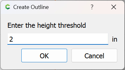
Just to confirm my understanding: The “Height Threshold” creates vectors at the point where the 3D object exists at that height?
Are there any rules about contiguous lines? Like…if it was a wave and I chose a height within the wave transitions…would it create non-contiguous lines / points?
