nukebert model part.c2d (120 KB)
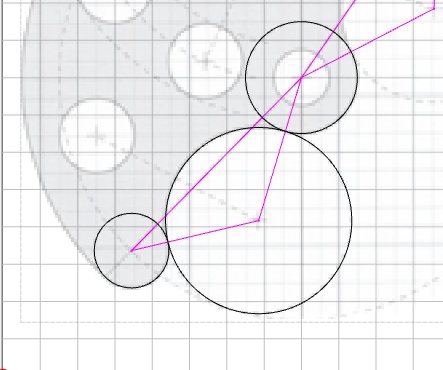
Try to trim & join the 3 circles. You first need to move the large circle to be as nearly perfectly tangent with the other 2 circles. I moved the other geometry out of the way…
nukebert model part.c2d (120 KB)
Try to trim & join the 3 circles. You first need to move the large circle to be as nearly perfectly tangent with the other 2 circles. I moved the other geometry out of the way…
As an update to the issue of Windows losing the Graphics setting for an application.
Using Fusion, I noticed the wrong GPU was being used.
I went through everything I previously stated with no success.
Now, I had been ignoring GEForce driver update notification. What a surprise.
I found that Windows will decide not to use a GPU if it determines the drivers are too old.
I updated the drivers to the current 8/28/2025 update.
So far so good.
The ability to drag a circle by its center point has been in previous CC versions. Is dragging a circle by its center point going to be restored in the next CC version?
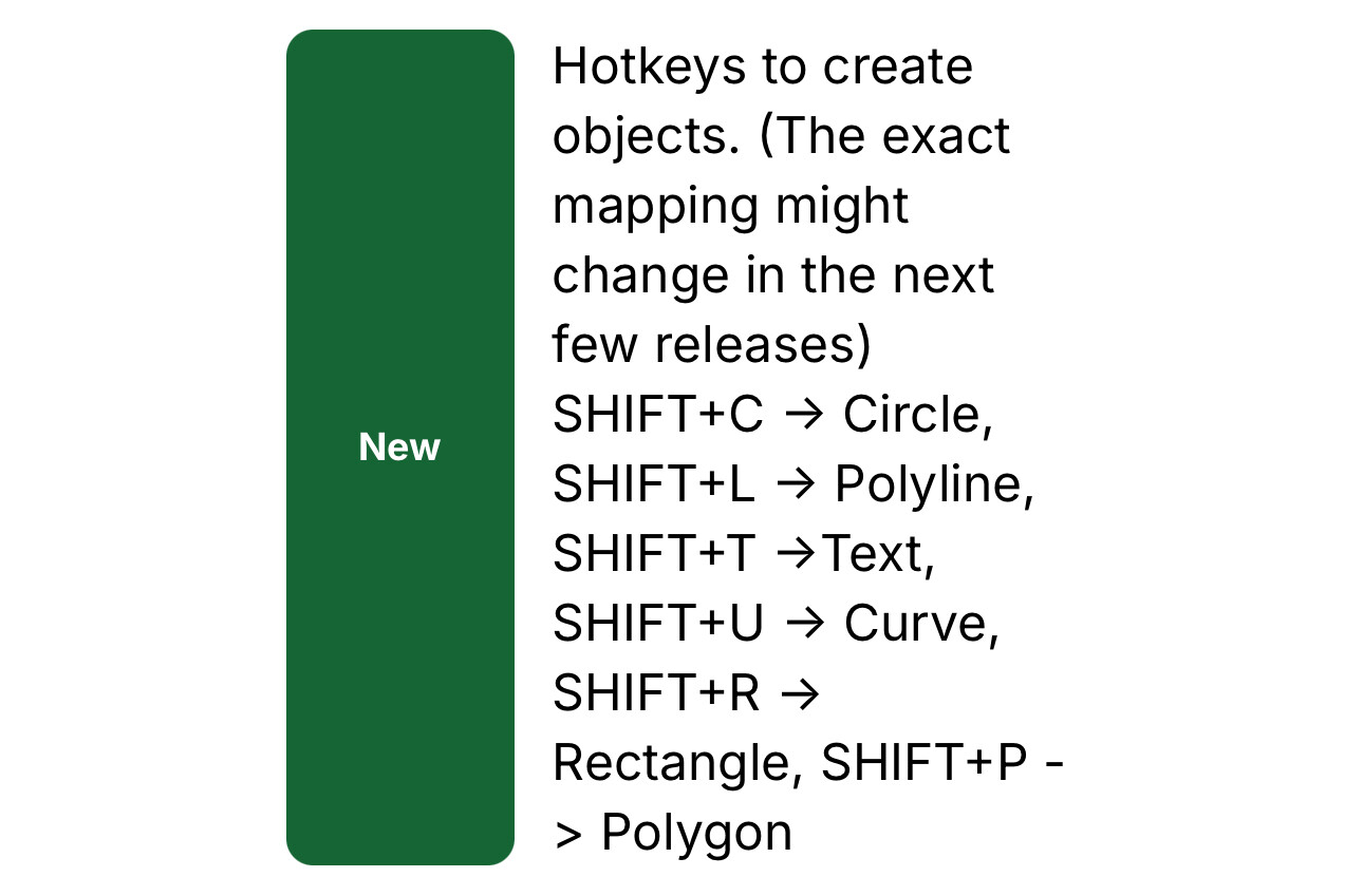
I want to say it’s a HUGE win for me to have the shortcuts! Many thanks for this upgrade. I finally got to use it for the first time tonight.
It would be nice if you could add the shortcut to the tooltip when you hover over the tool icon. You know, for us with memories that aren’t what they used to be.
I’d really appreciate a J hotkey for joining vectors. It doesn’t seem to have a hotkey, and I am using it a lot, and I don’t think J is used for anything yet… Thanks!
I was thinking the same thing as well when. That’s the natural “feel” of what I guess I’m thinking will happen.
@robgrz what are your thoughts on that sir?
Create 822 is posted to Carbide Create Beta Downloads
Three things I would like:
I think we’ll do that once the new keys/internals stabilize a little. Until then, we’ll try to keep this up to date: Carbide Create V8 (823) Keyboard Shortcuts
822 feedback. I ran through the changes/fixes and the shortcuts
Still can’t move a vector by dragging it’s center point. It deselects the vector.
When dragging a vector, it still snaps to it’s own (phantom) nodes
CTRL-F doesn’t appear to do anything
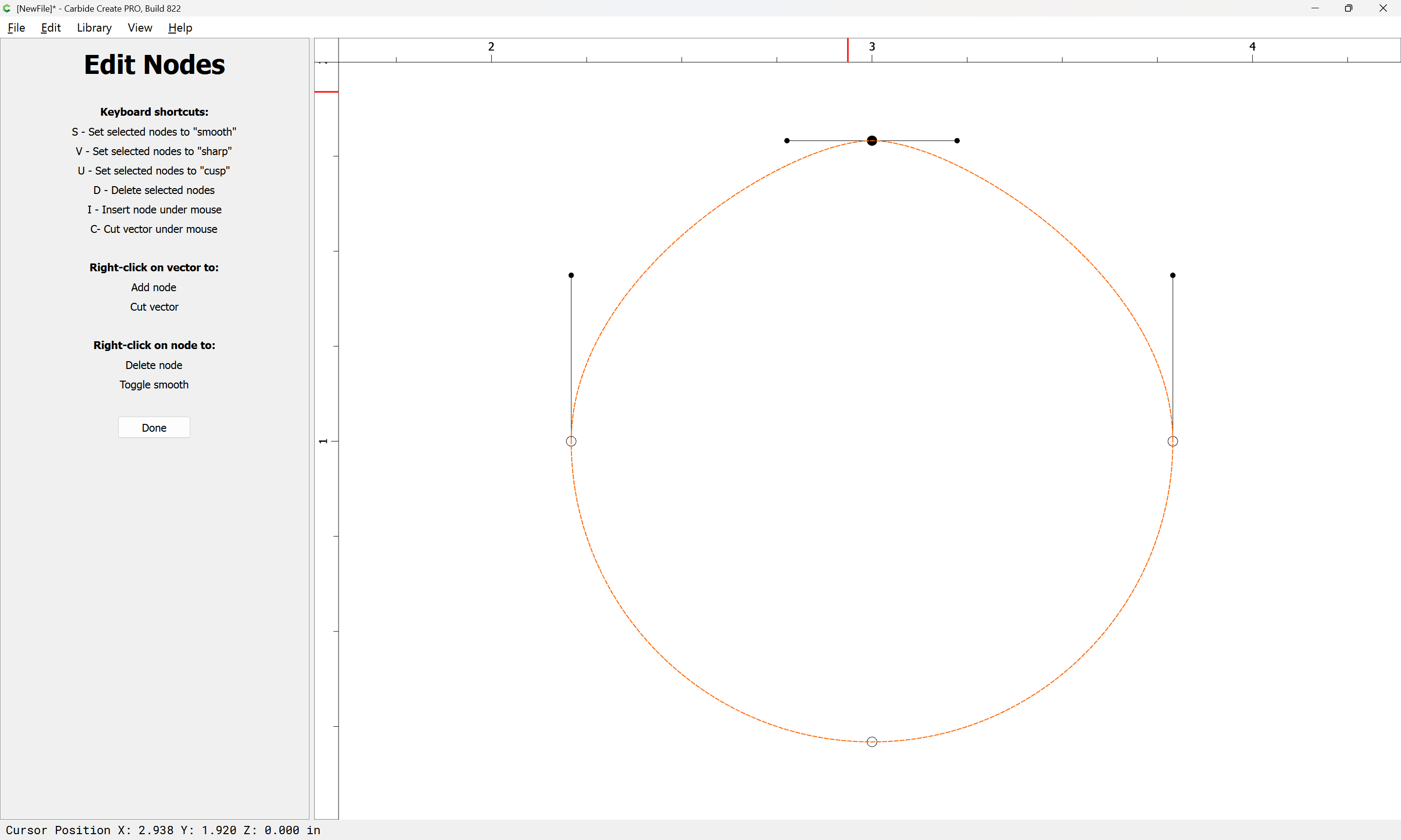
What is the definition of “cusp”?
What determines the magnitude of curvature (the length of the arrow) when smoothing a node?
I would expect if you made a square & then ‘smoothed’ it, it would become a circle. ??
Can the layer panel be made accessible in the model & toolpath views?
I created a line & added 2 nodes between the ends. If I delete the first node, it deletes the other end (the 2nd or End node)
I tried one with only one node added, and it reduced it to a (almost) point. These would be really hard to find!
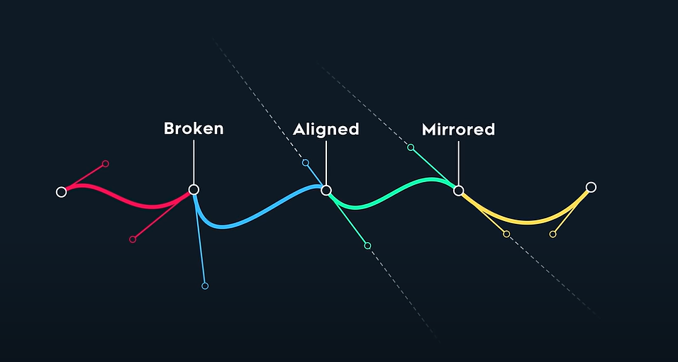
When drawing with a Bézier curve, there are several possible relationships between the on-curve node and the two associated off-curve nodes.
Freya Holmér did a wonderful video:

which examines some of the underlying math and has this definition/image:
where:
There is also the case of:
which is where the off-curve nodes are retracted/coincident w/ the associated on-curve node.
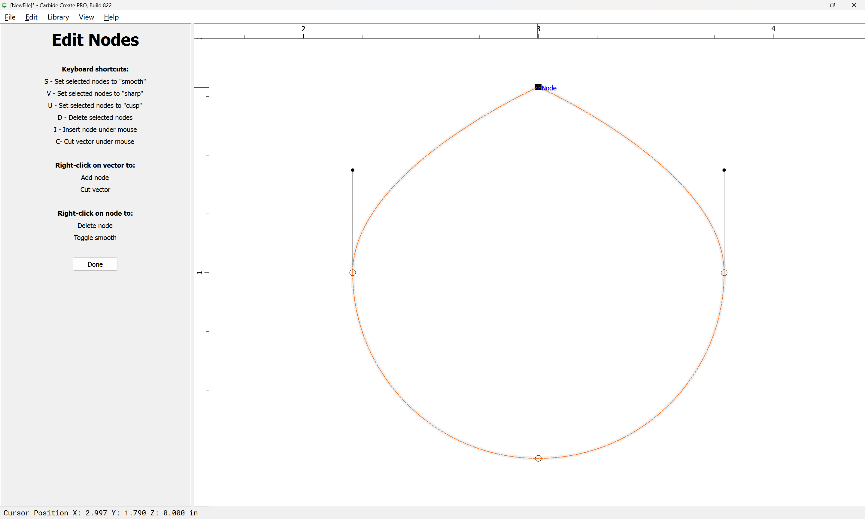
This seems to be hard-coded — cycling through the options in Carbide Create we get:
in addition to the Sharp node setting shown above.
Only at the specific size where the hard-coded dimensions for a Smooth node match up.
I don’t see how that could be made to work, and it seems a nightmare support-wise for me — the persistent Layer area in Design when working with objects makes sense, but a node has to be on the same layer as the object, and when working with Toolpaths, one wants that list, instead (if you want Toolpaths to correspond to/interact with Layers, assign them thus).
Thanks for catching that. After thinking on it and experimenting with it a bit, my take on it is since the singleton node no longer exists after exiting Node Editing (and usually if the penultimate node is deleted the last one goes as well), that’s a workable trade-off for allowing the user the ability to delete nodes as they wish.
That is a contextual command — it only works when an object is selected:
ctrl f
I have suggested that it should be overloaded to “Fit to Stock” when there is no selection…
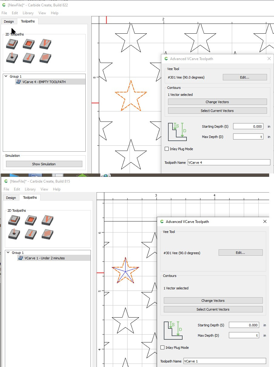
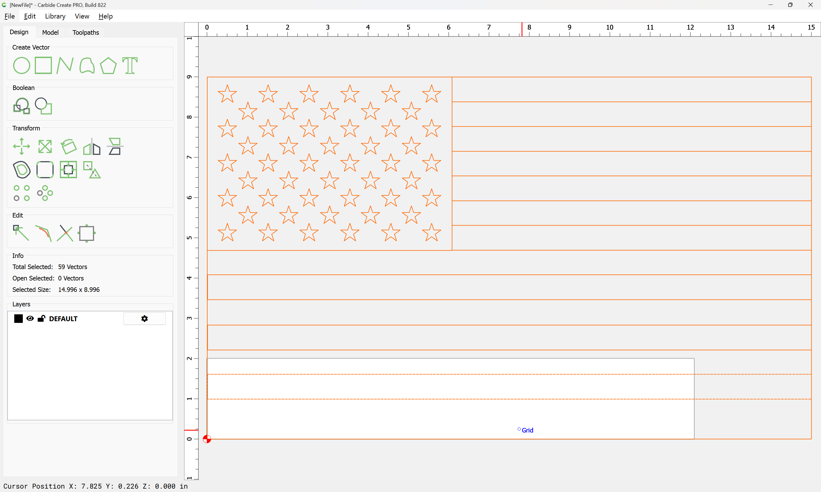
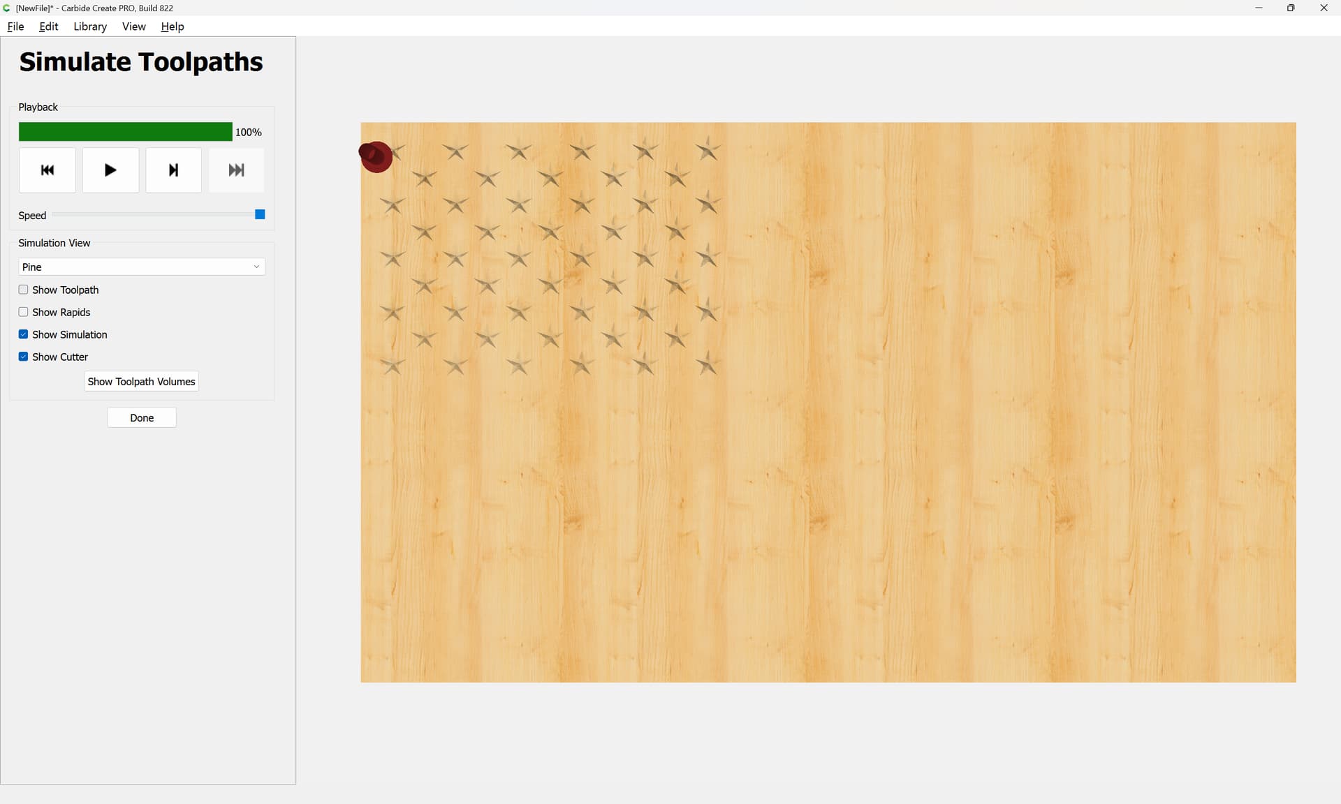
In 815: Load US flag from library, stock set to .5" thick, create vcarve, it works as expected. In 822 same process results in Empty Toolpath even after waiting a full minute and hovering over the toolpath repeatedly. Also, when hovering, it says the tool is a 1/8 in both versions even though the pocket tool is not enabled.
CTRL-F is listed in the shortcuts as “Fit to Stock”. Does it make more sense…
F (with nothing selected) - Fit to all geometry
F (with something selected) - Fit to the selected geometry
CTRL-F - Fit to Stock (Ignore geometry)
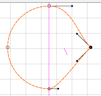
OK, it appears the “cusp” condition points the curvature vectors at the next node
I was asking what direction & magnitude the vectors would point with that condition.
The magnitude seems to be similar to the smooth magnitude.
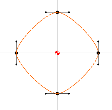
I don’t think so. If I try it with a very large circle or a very tiny circle, the results are the same.
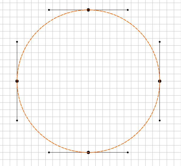
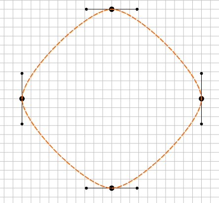
If you make a circle & examine the vectors, they appear to extend about 0.55 * R
If you then change the nodes to smooth, they appear about 0.3 * R
The vectors appear to be too short on any curve to truly “smooth” it. ??
OIC, the length of the off-curve nodes is proportional to some aspect of the size of the curve.
I still think if you go down small enough at some point there will be a (tiny/unusable) size where one gets something close to a circle — but no need for that, since one has a perfectly good tool for making circles (well, approximations of them).
Okay, import the file:
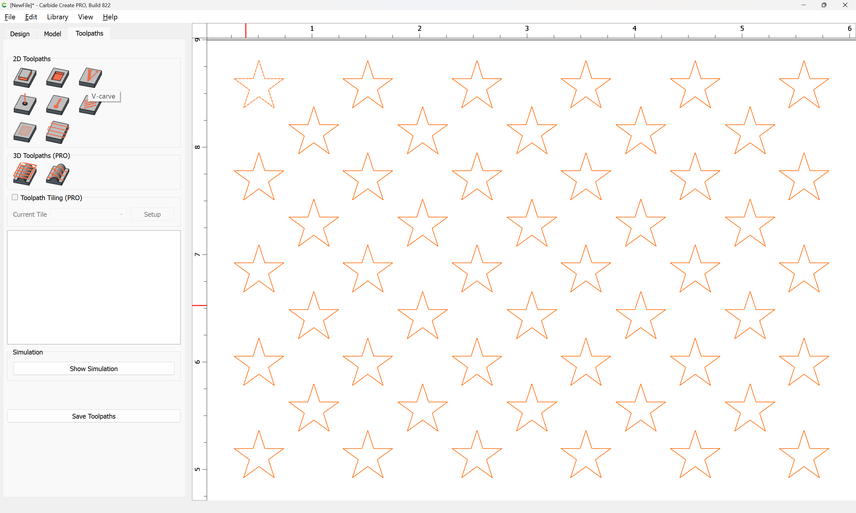
Select the stars:
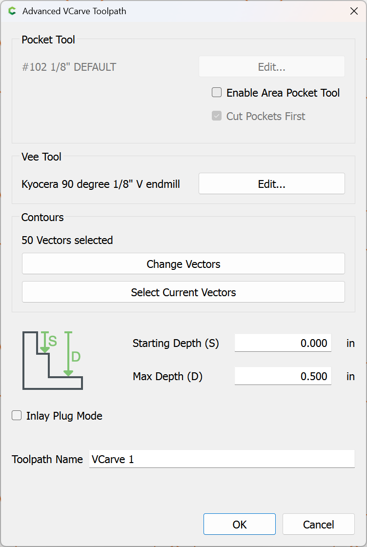
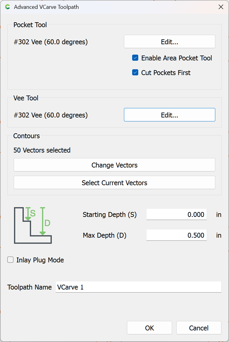
and assign a V carving toolpath:
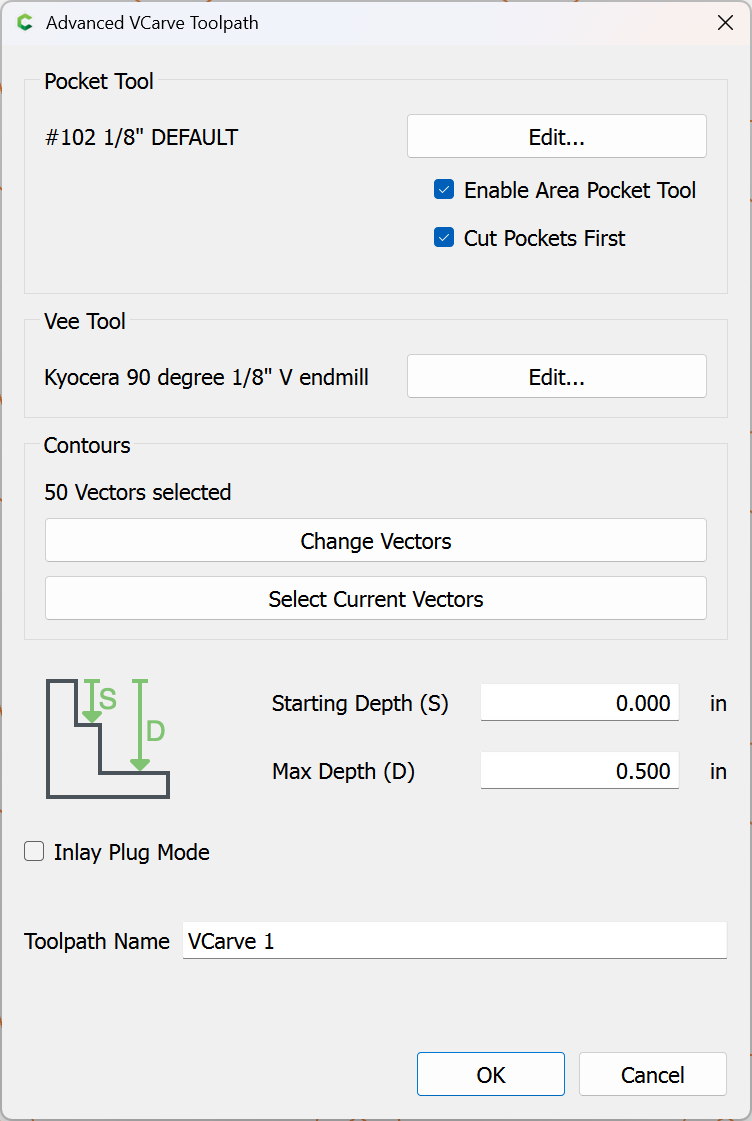
check the box for “Enable Area Pocket Tool”:
Edit the associated tool, selecting the same V tool which will be used for V carving:
Yes
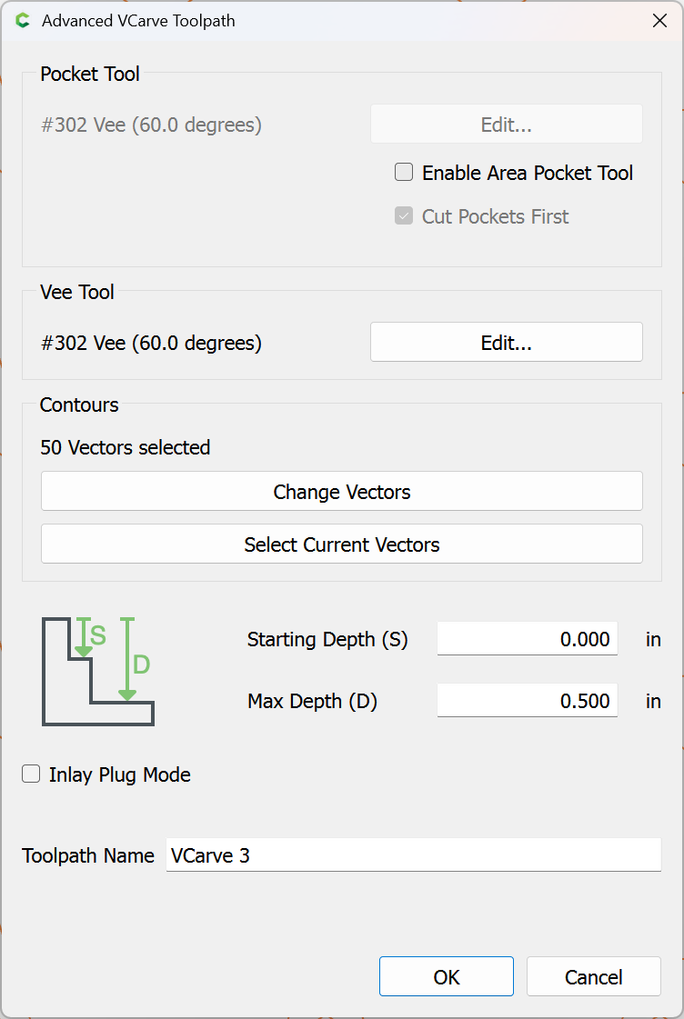
clear the checkbox for “Enable Area Pocket Tool”:
OK
R = 0.001, same results
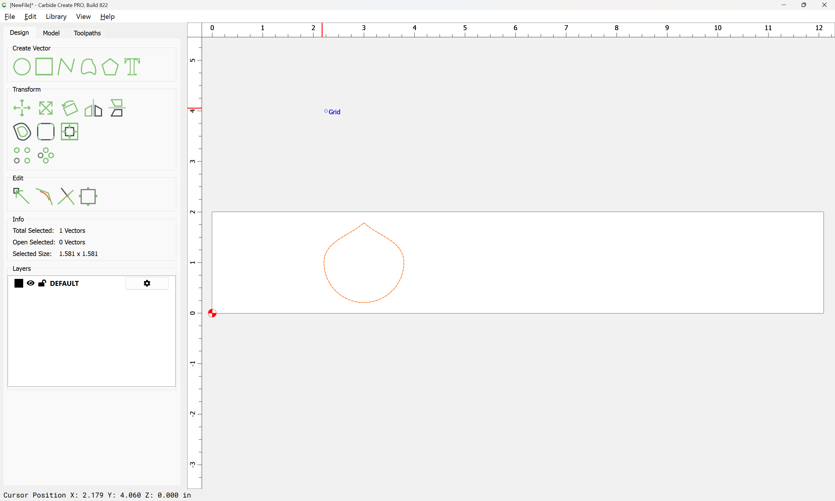
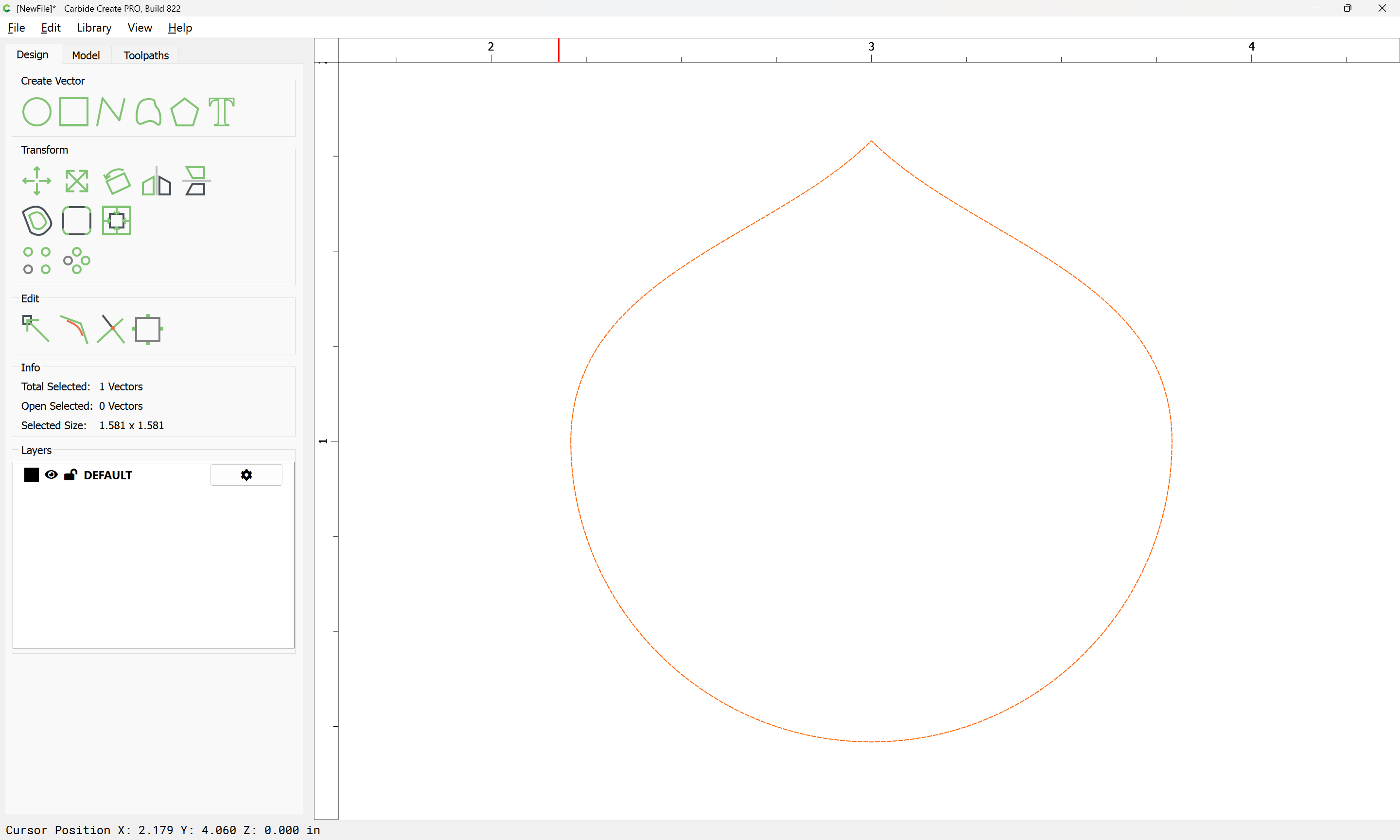
The problem isn’t really with circles since we can make those easily.
The circle just illustrates the issue better.
The problem is with bezier/nurb type curves, often imported with erratic spacing
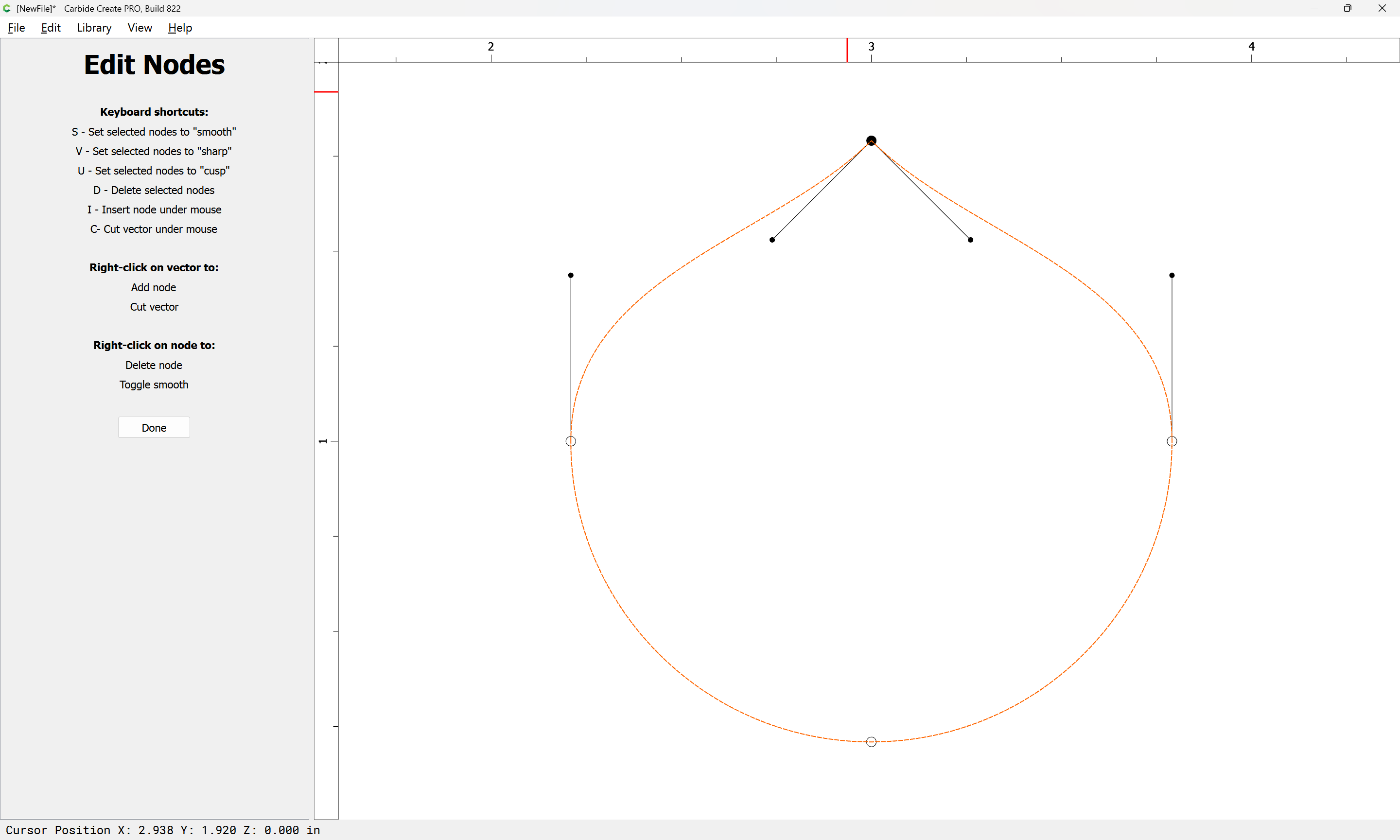
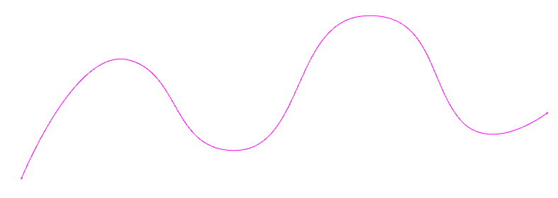
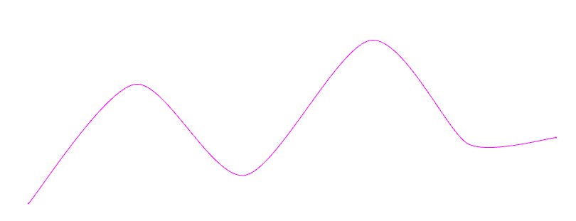
I’ve had several examples where I want to delete some of the nodes, then smooth the remaining nodes.
Before & after smoothing… i.e. what I would expect vs what I get
“Smooth” simply describes the type of node, not the actual effect.
It might be that it would be appropriate for the generated nodes to be further apart (perhaps following the “Rule of 30” where off-curve nodes are ~30 percent of the way towards the next on-curve node), but I view this as a default which gets the nodes created and makes it obvious to the user that they have the option of dragging them to the position appropriate to the desired appearance.
823 is posted to Carbide Create Beta Downloads
Unfortunately, the Windows build is unsigned again because Thales SafeNet is the Dell of security tokens.