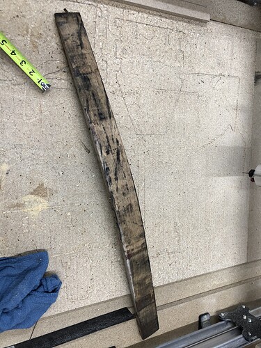
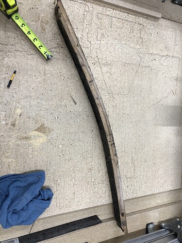
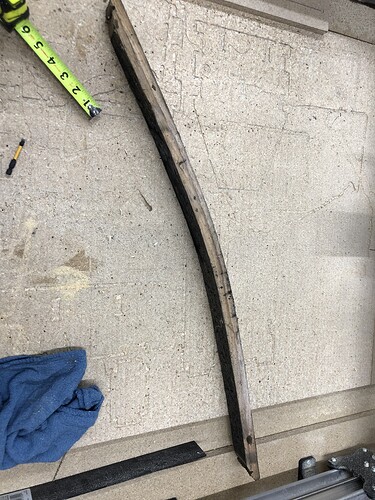
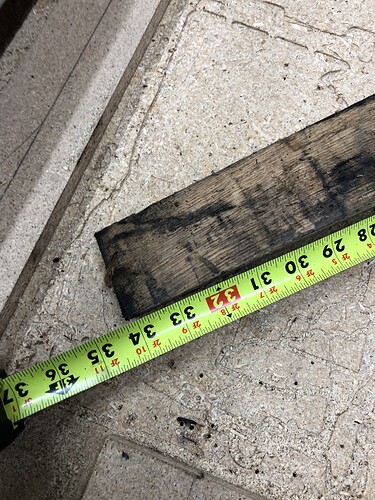
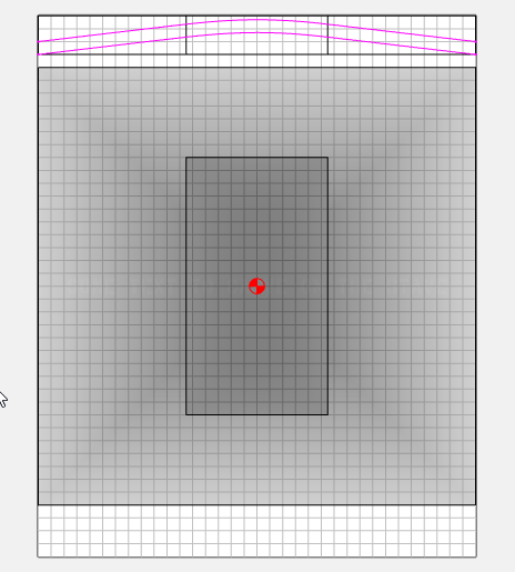
I made the assumption it was a constant curve (arc) through the cross section. It’s more like 2 lines, or 2 very large arcs, with a smaller arc in the middle. I took a guess & made this cross section using your dimensions. This could be refined by taking a few more measurements along the cross section.
To build the model you need to make the workpiece much larger than the actual finished part.
I made my workpiece 34 x 42 so I’d have room for the model plus the cross section.
Create a large rectangle for the angled portion, and a smaller rectangle for the curved portion
Now add your profile just to use as a guideline to place the text. And add your text.
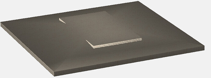
Now build the model.
Select the outer rectangle & make a Angled component, 45° is OK, Scale height: 2", Merge type: Add, Base Height: 1"
Then select the inner rectangle and make a round component. Scale Height: 0.348", Merge Type: Equal, Base Height: 2.353"

Now subtract the text. My text is about 0.160 wide, so I’ll use a 1/8" tool & cut 0.0625 deep.
Select the text, create a flat component, height: 0.0625, Merge type: subtract.
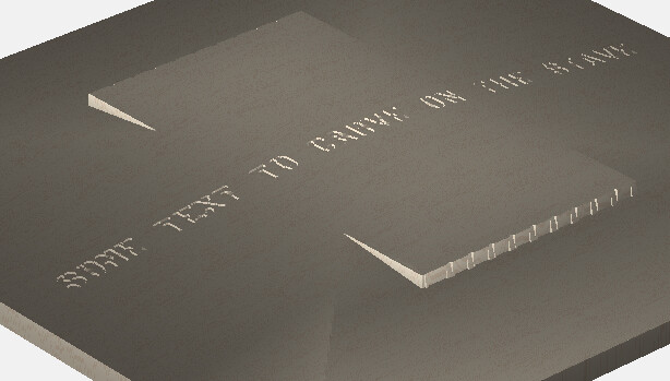
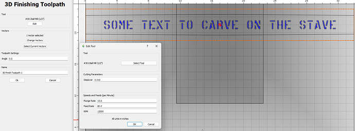
Now Toolpaths. I’m going to use the 4 x 34 rectangle to cut the curvature of the stave just for display purposes. I won’t use this path on the machine. It’s just for the simulation.
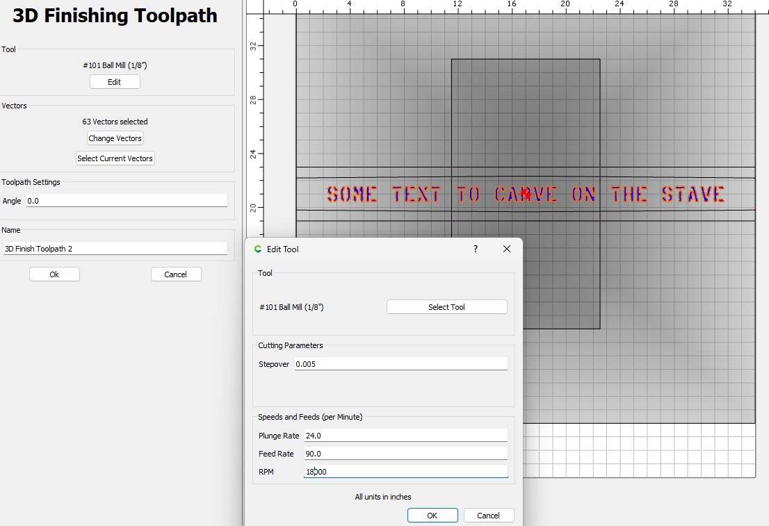
Now select the text & create a 3D finish path. I’m using a 1/8" ball.
Disable the first path, and output your g-code or save the CC file to send to the machine
For reference:
Brian_Hubbard_Stave.c2d (452 KB)

