If I have a 1.25" wide hexagon pocket in the middle of a piece of wood and it’s 3/4" deep and I want to put a 0.10" deep chamfer around the top of the hexagon, how would I do that? can I use a 90 deg V-bit and a contour path set to a depth of 0.10 or would I need to do it as a v-carve or use a chamfering bit?
thanks!!
That’s what I would do.
1 Like
The geometry of a chamfer tool (being a taper) means that the Z offset from the part edge has a direct relationship with the width of the chamfer when navigating pockets with interior angles. There is a maximum allowable offset to get an even chamfer all around the hexagon. Exceeding that will result in a deeper chamfer in the corners.
I would recommend doing this in CAD, and then simulating the toolpath in CAM.
1 Like
I’ll add that technically the point of a (perfectly pointy) vbit has a cutting speed of zero, which is not great for cut quality. So sometimes it is worth offseting the contour toolpath by a certain amount, and increasing the Z depth accordingly, such that the chamfering action happens using the “middle” of the vbit cutting edge. For a 90deg vbit the compensation is easy (for other angles you need to throw some more math at it)

But then again, in wood it does not really matter and the simpler approach of just following the original profile works.
If you can tolerate a little bit of rounding of the inner corners of your hexagon pocket, a profile toolpath (offset or not) will do.
if you need perfectly sharp inner corners, then you could do the chamfer as a vcarve op, creating an inner offset profile (offset inwards by twice the depth of the chamfer) and use that and the original profile as the boundary vectors for the vcarve.
7 Likes
What a good question by the OP, with really great answers!
I’ve not yet gone past cutting the tops of my boxes with square cuts, but with this technique I could form a small chamfer between the box lid and box bottom, making it a little easier to open while keeping a slight interference fit!
Thanks for asking the question, @WVDesigns 
1 Like
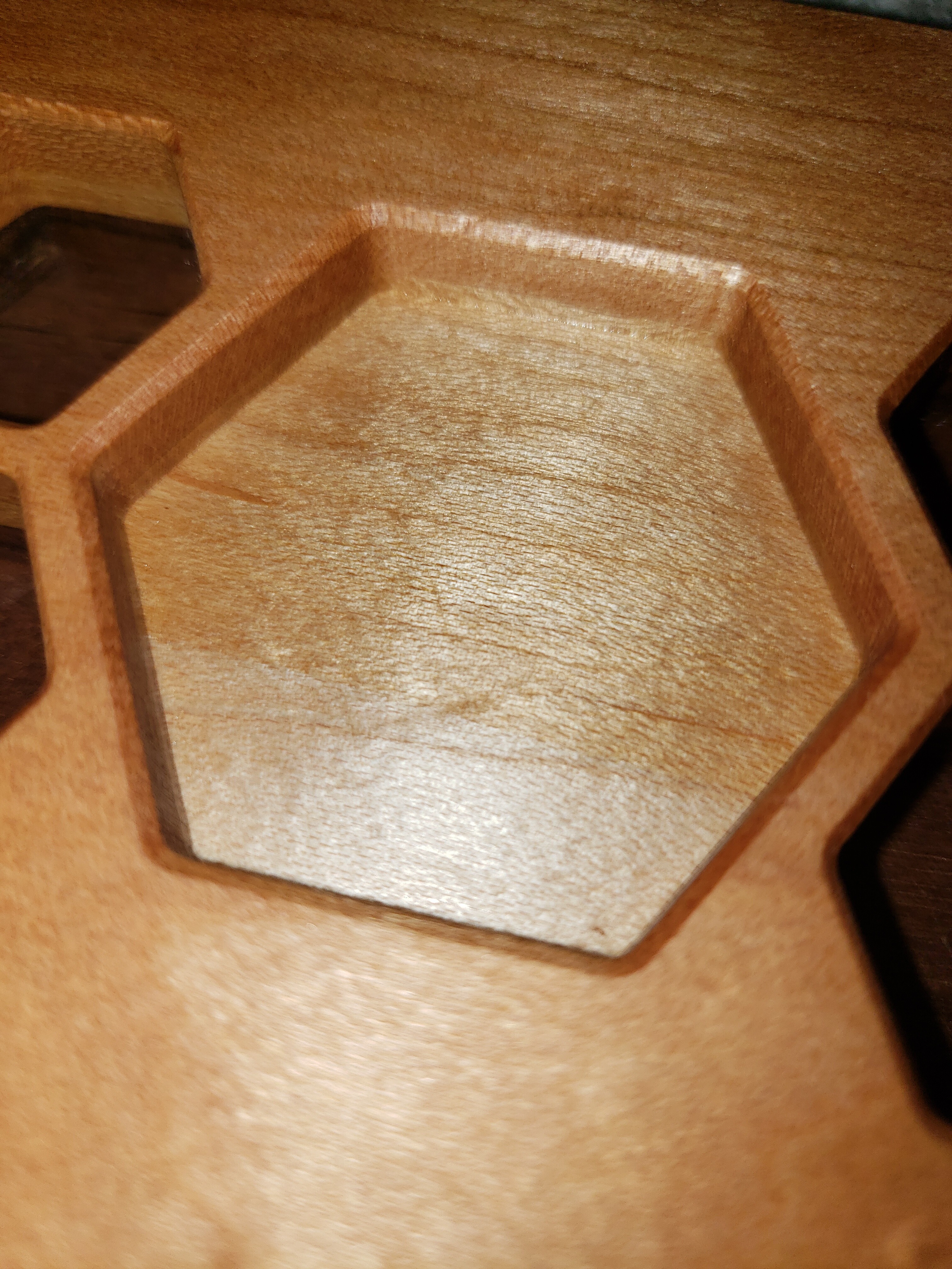
so what I ended up doing is ran a contour path on the inside set for 0.10" deep using an 1/8" endmill, but I installed a 90 deg V-bit into the router and it came out perfect. i know it’s not advisable to mix it up like that, and I was close to getting a v-carve to work, but it just wasn’t 100% like this was.
8 Likes
Was that done with a zero offset or the .10” offset?
Looks clean!
So the chamfer is more like a 0.04"?
I had figured out how to trick the program to work, but it’s not scale-able. so i’m back at trying to learn how this works. Julien, you mentioned rounded corners, that’s actually what I’m looking for, a nice easing of the sharp edge all around the hexagon pocket. could you walk me through a set-up? i have a 1" wide hexagon that’s .5" deep and i’m looking to put a small chamfer on it maybe a 1/16th". I’m getting bogged down in the stepover part (no understanding of the concept) and i’m not sure if I should run it as a contour with no offset or with the inside/left option. with the no offset it plows a groove in the top edge of the hexagon (maybe where stepover would help?) on the inside/left option it seems to run in the middle of the hexagon, as if the program is measuring on the outside edge of the .5" vee bit and not at the point. any thing would help, this one is stumping me!!
1 Like
What the “inside” option does is that it will shift the toolpath inwards by half the diameter of the selected tool, such that the edge of the tool touches the inner side of the vector. But while this is fine for a square endmill that has a constant diameter, for a vbit it does not really make sense, because CC will subtract half the declared diameter of the v-bit, and that’s the max diameter at the very top of the V, so it’s a large value like 0.5", which is why you end up with the toolpath moving “in the middle of the hexagon”
So let’s focus on only using a no-offset contour toolpath. The thing that may have caught you is that CC unfortunately does not render correctly contour toolpaths when a vbit is selected. It will show a flat-bottom slot instead of a V groove as it should. But while the preview is incorrect, the generated G-code is fine, so if you do run that no-offset contour with that vbit, you should end up with the nice chamfer you want. In fact this similar to what you did last time, by generating a toolpath for a 1/8" square endmill but then actually using a vbit. I had not noticed, but you did mention that you used the “inside” option, and that’s what made things non-scalable, because then there was a dependency to the 1/8" dimension. Just make that a no-offset toolpath, and whichever tool is loaded will have its tip move along the contour at the programmed depth of cut.
The only remaining thing is to determine the depth of cut, to get precisely 1/16" face width for the chamfer, it that matters. With a 90° Vbit, the face width is (depth x cos(45°)) so that’s 0.7*depth. To get a 1/16" face width, you would set the depth of cut to 0.044". But then again maybe when you said 1/16th chamfer you meant the height/width of the chamfer legs, I’m no machinist so I don’t know how one properly characterizes a chamfer dimension. In that case of course just set the depth to 1/16".
So, to circle back to @neilferreri’s post #2, just use a contour toolpath, no offset, 1/16" or 0.044" depth of cut, with a 90° vbit, and it should work just fine.
And THEN, if you ever get fuzzies or a less-than-sharp bottom edge of the chamfer, you can optimize a bit further by shifting the toolpath inwards, and go proportionnally deeper, as I tried to illustrate in my post-it notes earlier: you would:
- select the hexagon contour
- use the “offset vector” tool in CC, and create an inside offset by e.g. -0.05". You end up with a slightly smaller hexagon shape, you select that and create a no-offset contour toolpath based on it. But this time you need to cut deeper to get the same chamfer face width as before. Exactly 0.05" deeper, for a 90° vbit.
I really hope I did not add to the confusion ![]()
1 Like
Julien, thanks for the very clear and easy to follow explanation!! I ended up figuring out the last option you suggested and so far it seems to be working good after a dozen tests on different sizes and shapes. It was nice to see it as one of your recommendations to give credibility to that method.
Thanks!
1 Like
This topic was automatically closed after 30 days. New replies are no longer allowed.