Choosing Endmill Helix Angles

Kind-of like it would on a router table where you’d likely use 24,000 RPM for anything less than 1" diameter in the “New World” (where most router bits only have 2 flutes)? I’ll bet you didn’t get much tear-out on the faces though, right? Even if you were cutting Baltic Birch, your cutting forces probably wouldn’t have caused a router table user to slow his feed rate.


Your Chip Thickness was 0.0012", which should make @Julien happy. Measure/log spindle currents and try it again with 45 degree helix up or down cut?
Measure noise too?

3 Likes

The helix angle for your posted endmill image looks like 0 degrees to me.

There was very little tear out, a little fuzzy but the finishing pass dealt with most of that. It wasn’t super high quality ply and no, the spindle didn’t even blink. I was watching the output Amps on the HY VFD and it went from 1.9 to 2.2 during the cut so the spindle was basically idling.

This is that bit doing a slightly slower adaptive clear in a pocket;

4 Likes

When/how much do you sleep (assuming that you do get some sleep)?

1 Like

After a lifetime of working with US employers and customers I am roughly on EST :wink:

4 Likes

Interesting question. And yes, you’re right, you can pick the helix angle to ensure full axial engagement even for a radially narrow cut, so that the cutting forces are essentially constant. Here’s some data:

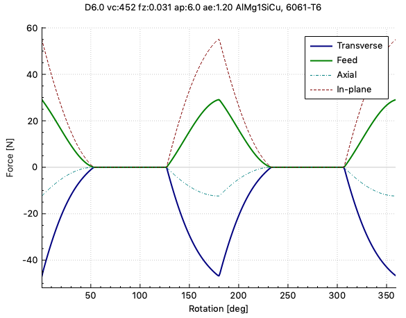
Forces (Newton) for one revolution for the SECO JH40060, which has a very sharp edge at low helix angle (25 degree):

fha25

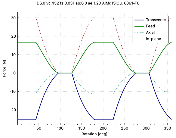
Keeping everything the same, but changing the helix angle to 40 degree:

fha40

And finally 55 degree:

fha55

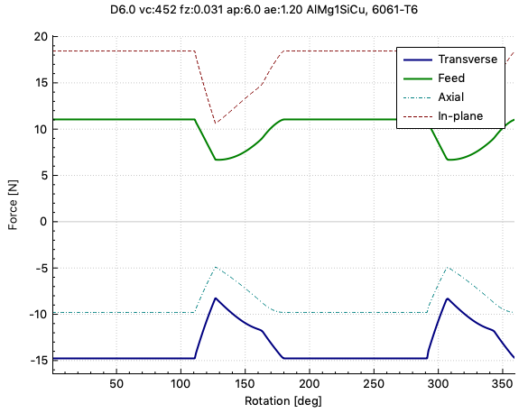
This last would be close to what you suggest, forces practically constant. Iff, and that’s the problem on a Shapeoko, if you can keep the chips from clogging up the flutes (just my impression with higher helix angle endmills).

9 Likes

Interesting,

Could you explain the force directions on the chart a little more pls?

I think I get axial, this would be vertical forces up and down on the cutter.
Feed is presumably in the feed direction, i.e. the direction the spindle is moving.
In plane and transverse though?

Also, what software did you use to get this data from?

Thx

1 Like

Yes, positive feed force pulls the tool “forward”, sort of supports the steppers, negative holds back. Transverse is perpendicular to the toolpath, positive to the right when looking into the direction of motion - in this example here, negative transverse force means the tool is pressed away from the workpiece (climb cutting). Axial is positive when the tool is pressed into the spindle, negative here.

In-plane force is the magnitude of the vector sum of the feed and transverse forces. This is what your weakest axis motor needs to drive/hold in the worst case, a very critical value for the shapeoko, as I have found out (ouch!).

6 Likes

Thanks,

That is really interesting.

From some previous discussions I believe the received wisdom is that the Shapeoko is better at cutting harder materials using a shallow depth of cut with a higher width of cut. Would it be possible for you to show a comparison of two equivalent removal rate cuts but trading width for depth to see what happens to the forces? e.g. trading 0.5mm DoC at 3mm WoC for 3mm DoC at 0.5mm WoC

3 Likes

Here’s the comparison you were asking for (harder material? let’s go 7075; tool this time is WNT 53501060. But please read to the bottom of this post…

0.5 mm axial by 3.0 mm radial

3.0 mm axial by 0.5 mm radial

So, for your constraints, it’s a wash, more or less. However, is this the question you should be asking?

More often, we may want to know which parameters to choose to reach the highest removal rate given the limitations to the machine - and that’s not the same problem, because this stuff is not very linear: you can’t always simply scale. So the answer is … it depends.

8 Likes

What calculator did you use?

1 Like

That’s interesting.

What I was wondering was whether there was some sign in the data of why the machine was less happy with the total MRR when taken as a deep narrow cut rather than a shallow wide cut. It’s quite frustrating to only be able to use 0.5mm of each cutter.

As you say the forces are quite similar, also they both show as pulses of similar width. Once machine deflection is taken into account things may change.

We might reasonably expect in the region of;

  • 0.25mm lateral deflection for the 3mm WoC given the 41 N peak lateral load
  • 0.2mm lateral deflection for the 3mm DoC given the 33 N peak lateral load

But these deflections would change the effective cutter engagement and therefore the forces (in the first pass, in the second we’d end up having to take that extra material if we’re stepping over by the WoC)

  • 0.25mm in the shallow cut is subtracted from (correct sign?) the existing 3mm width of cut to give 2.75mm (92% of original) and the cutter pulls about 0.08 in the feed direction
  • 0.2mm in the deep cut is subtracted from only 0.5mm width in the deep cut giving 0.3mm (only 40% of original) whilst the cutter pulls 0.16mm in the feed direction

So whilst the initial deflection is smaller in the deep cut the total engagement change is quite a bit larger, this might be a pointer to what’s going on when we try to swap radial for axial engagement, larger changes in forces giving us a stronger vibration input to the spindle.

There’s a bunch of simplifications in there, we know the Shapeoko deflection is not symmetric in the X and Y axes at all and there’s a bunch of coupling in the Y and Z deflections too. Also those cutting forces were calculated assuming a rigid machine?

Thoughts?

@gmack have I completely jumped the shark?

I’m assuming there’s existing research already done on how machine and cutter deflection impacts cutting forces and how those variables interact to impact overall machine behaviour, but I haven’t seen any of it.

2 Likes

Maybe because people aren’t using enough of the endmill helix to smooth out the cutting forces as shown feasible in @spargeltarzan’s first post? Note that he apparently used an axial DOC equal to the endmill diameter. Many endmill manufacturers recommend 1.5 - 2 times that for side milling (enabling lower helix angles).

LOL - I had to look that one up even though I used to watch Happy Days! But, this is exactly the kind of input/feedback I was hoping for. :grinning:

2 Likes

Let’s say it’s part of expanding Julien’s colloquial english vocabulary :wink:

4 Likes

Absolutely. Thing is, the signs in the data depend on machining conditions, it’s not so easy to make a general statement one way or the other. In your question, you constrained it to just swapping radial and axial engagement, but that yields thinner chips for the case with small radial engagement. Thinner chips mean smaller shear angle, leading to larger shear strain and strain rate. In ductile materials (metals), flow stress increases with strain. In short, 3.0/0.5 vs 0.5/3.0 while keeping feed (MRR) is not “fair” comparison. For example, as @gmack points out, you could go further and increase ap much more to reach the point where exactly one cutting edge is in engagement all the time, and reduce feed and ae to push the - then practically constant - forces down.

Certainly - deflection changes everything. I think you’re using the belt flexibility for your computation. But the peak loads occur twice per revolution, that’s 833 times per second. The tool itself and maybe the spindle shaft you can excite at frequencies that high. But the belt/V-wheel/whatever upstream flexibility only sees the loads filtered by the z-axis assembly mass, more or less the mean forces averaged over one revolution. So for the tool deflection in the shapeoko, use the mean forces.

Good thinking. And you’re right, while the first pass with high-ap, low-ae will see lower than nominal engagement, the second pass will be a lot worse, precisely as you say, although probably not quite as much.

Yes, the loads are for a rigid machine. Accounting for flexibility correctly makes it a fully dynamic problem, everything is a function of time and the graphs become indecently messy. Sometimes it can still be useful to see the machining forces that excite the dynamic system in the first place, even if they will change with motion (a lot).

3 Likes

The manufacturers’ recommendation might also have to do with tool life.

With a little simplification, the axial engagement ap for which exactly one edge is always engaged is, if I got my sketch right,

image

where D is tool diameter, n_f the number of flutes and \lambda_s the helix angle. This will “smooth out” the forces over one revolution. That gives:

2 flutes, 25° helix: ap/D = 3.4
2 flutes, 55° helix: ap/D = 1.1
3 flutes, 42° helix: ap/D = 1.2

That said, sometimes reality catches up with that theory when the pocket to cut ain’t that deep…

8 Likes

In Fusion360 you can set “minimum axial engagement” and its says that its commonly used to keep at least one flute constantly engaged and can reduce tool wear and chatter.

I haven’t used it but gonna ask the bossman about it tomorrow. Could definitely have a positive benefit with our hobby machines.

5 Likes

Thanks for that! Do you think this topic should “close in 14 hours”?

Definitely not, we just gotta message a mod, no problem.

I know alot of what you guys are throwing around is theory and honestly I even have to read these posts multiple times to make a bit of sense.

My new day job is to prove out cut recipes for hobby machines. Would love to start playing with helix angles and how they effect things.

And would love to use that calculator, Haha.

8 Likes

I have enormous respect for you sir! You were an early pioneer in this forum by empirically demonstrating, by seemingly unbiased trial and error, that high cutting speeds can be really useful for maximizing the performance of “hobbyist machines”. Thank you! :star_struck:

9 Likes