Yes, that should work. You should be able to get them half as cheap though, examples:
1 Like
Agreed those should work. Do you have wires to attach things together? The joystick have a few wires flying off of them but they are very fine gauge, and the x and Y potentiometers do not have any wires yet, at least on the ones I got. You will need to solder wires on and then have some way of plugging them into the Arduino.
1 Like
ok thanks,
i have wire, soldering material, and i know how to solder. i just need to have a plan or instructions… but i’ll ask you later.
so we can make a tuto, for the next ones.
should there be buttons? to enter functions? X Y Z?
there is no need for a molex plug?
It’s up to you if you need other buttons or not, I would probably at least add LEDs so that you can indicate what axis and speed is active. Would be useful even just for debugging.
2 Likes
Hello to all,
I received what I ordered, to put a joystick on my shapeoko.
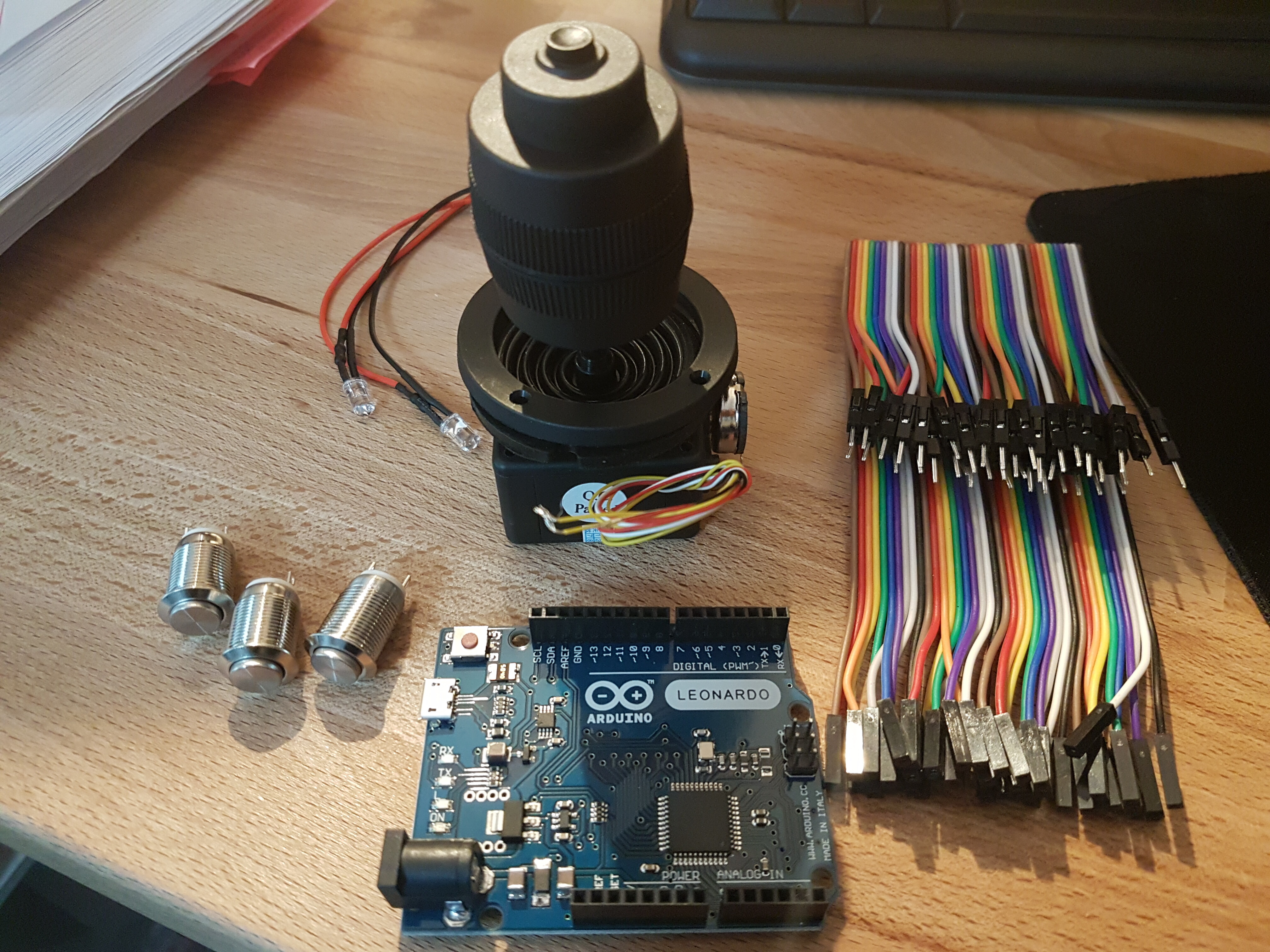
joystick, carte arduino leonardo, 20 leds, 10 boutons…
But I’m a bit of a noob in electronics, and I would like to have some ideas…
button for X Y Z, buttons for speed adjustment? joystick, leds, what else?
do you have plans for the electronics?
Can I configure a joystick with carbide motion? Or do I have to use CNCjs?
I’m waiting for your help and ideas.
@Julien @theworkshope …
vivien
3 Likes
Diving head first into it, great ! ![]()
Do you have one of those:
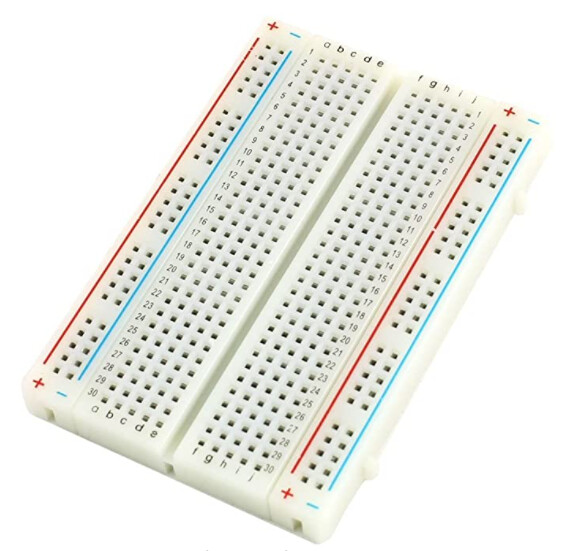
It helps immensely to prototype your circuit before making the real project.
I suggest you start by:
- learning how to set a GPIO output / toggle a LED with the Arduino
- learning how to set a GPIO input to read the state of a button or the value of a voltage.
With those two things you are well on your way to become an Arduino master ![]()
The arduino.cc site has plenty of tutorials, e.g. https://www.arduino.cc/en/Tutorial/BuiltInExamples/Button
A minimal setup you may want to try is connecting a set of buttons and LEDs to the arduino, and programming it such that each button lights up a different LED.
And in parallel, start thinking about what you would like your control box to look like. The joystick obviously for jogging, and since this is the core of the function I would start by not adding anything else. But this is slightly more complicated than just reading a button, so once you’re at that point we can cover that (and leverage @mindle’s source code, he did all the hard work already)
@mingle’s example code above is for CNCjs. You could derive a version that could work with CM, because the Arduino can behave like a keyboard. It may not be the ideal beginner project, but with a little forum help…why not.
2 Likes
ok I’ll look at it tomorrow, thanks.
and no I don’t have this thing here, to make a prototype… what is it called?
Breadboard
1 Like
ok I like the idea of not being stuck on cncjs only.
and i followed your advice, i bought a starter kit for beginners  so i’ll have everything to start and learn.
Maybe in the future, I could make a lot of stuff for my home…
@Julien it seems to me that you have made a lot of things in arduino at home ?
after that, the hardest thing for me to learn is English, I have to spend time to translate everything … it’s hard
This, my friend, is how it begins, you just caught the Arduino bug! Sorry ![]()
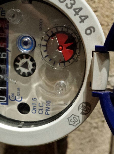
You can have all kinds of fun (some would call it "spending way too much time to make something one could have bought from the store). I lost track of how many arduinos and Pi I have at home, in various states of working conditions and usefulness. One that has been working for years now is a very simple one I installed on the face of my water meter which has a spinning wheel with a shiny/reflective half:
I used one of those $4 IR sensors:
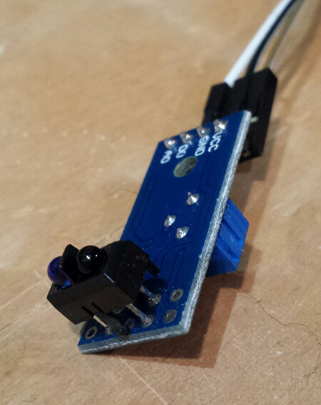
and mounted it onto the water meter facing the spinning wheel,
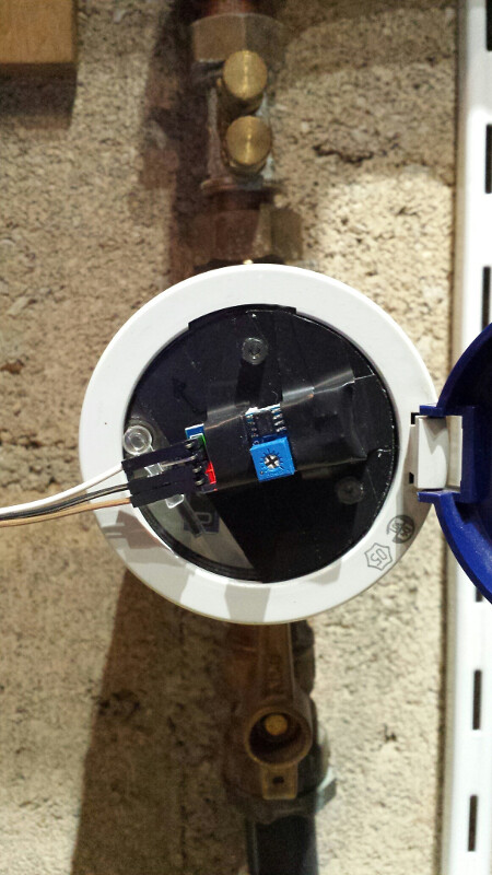
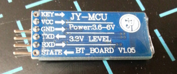
and then a little Arduino sauce to detect the variations in reflected light to count the wheel turns, a cheap Bluetooh module,
and I have a sensor that logs my water consumption.
But now I’m diverging from the Joystick pendant topic…
It is hard, but also an excellent way to learn (more) English. And we’ve got your back!
4 Likes
Do You have to pay per m³?
Yes, in France we pay per m3.
2 Likes
They haven’t started with that here, yet, but I guess it won’t be long until the greedy politicians do here too.
How much is it for a m³?
Around 5 euros per m³ (and rising)
Admittedly, it helps everyone be aware that this is a precious resource (and yet…greedy politicians and corrupt water management organisations, too)
2 Likes
Hi,
I found this yesterday while doing some research. What do you think? @Julien
https://www.crazy-logic.co.uk/archives/1053
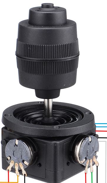
I am looking for a diagram to wire my joystick JH-D400X-R4-10K avec une carte leonardo.
thank you for those who can illuminate me… 
I am back from vacation so can diagram this for you today. The Z axis wire coloring is weird on these but the X and Y pots are as expected (middle is the changing/sense line). How you wire them up affects directionality, but you can always flip that in code (should pushing in a particular direction result in positive increasing values or negative values).
2 Likes
here is my joystick with the wire colors. they are not like on the video.
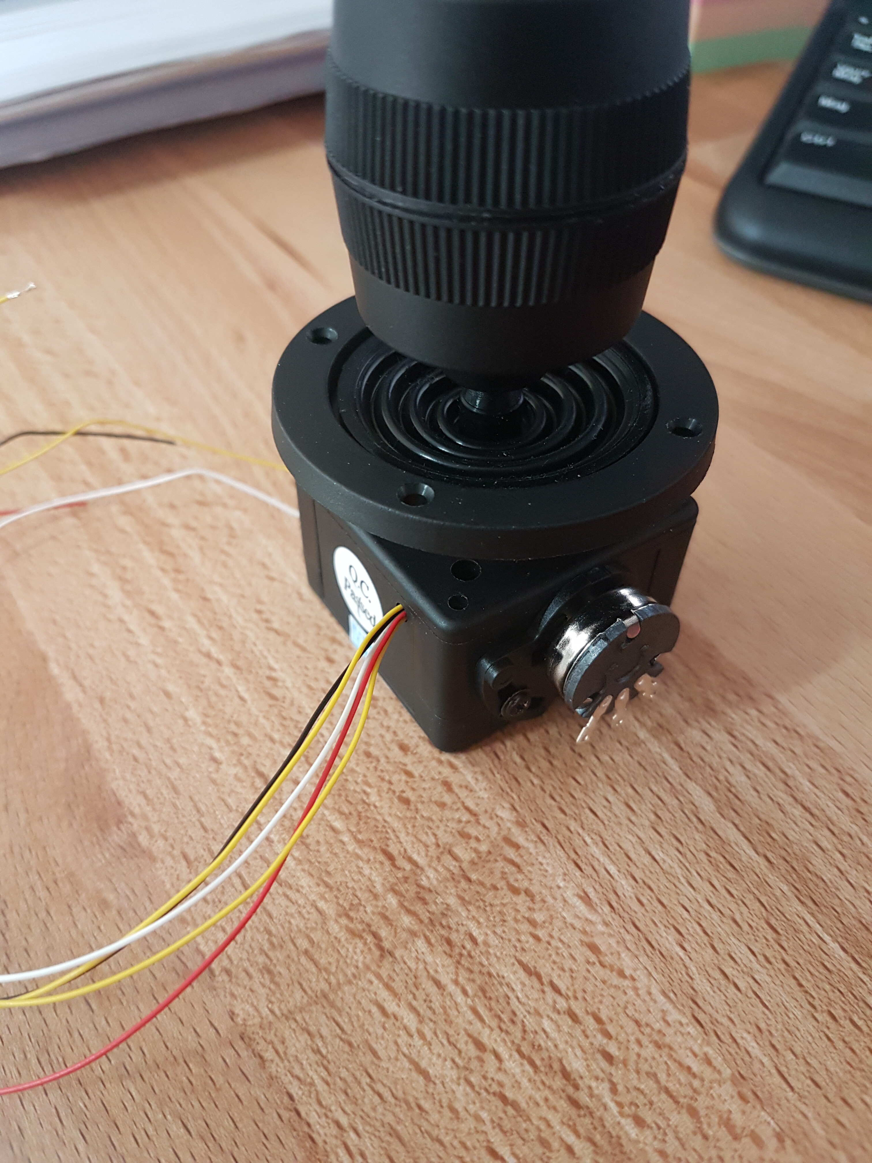
thanks for your help. @theworkshope
1 Like
@Bwood34 That’s how mine look as well. Try this out -
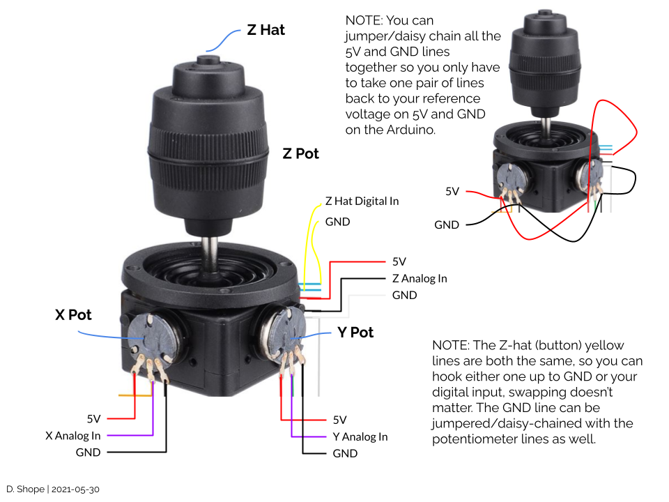
My convention was just to use something other than red/white/black for my analog inputs, in this case purple. Yellow lines were used for buttons since the Z-hat already started that. I would use 22ga or something similar rather than the 30-ish ga coming off the Z lines for durability. Once you are happy with you wiring you can also use hot-melt glue to strain relieve the cables to the bottom of the joystick. Just make sure you don’t gum up any of the moving parts ![]()
Following this diagram you should have the following back to the Arduino:
- 5V
- GND
- X Analog In
- Y Analog In
- Z Analog In
- Z Hat Digital In
3 Likes
cool thanks for the info.
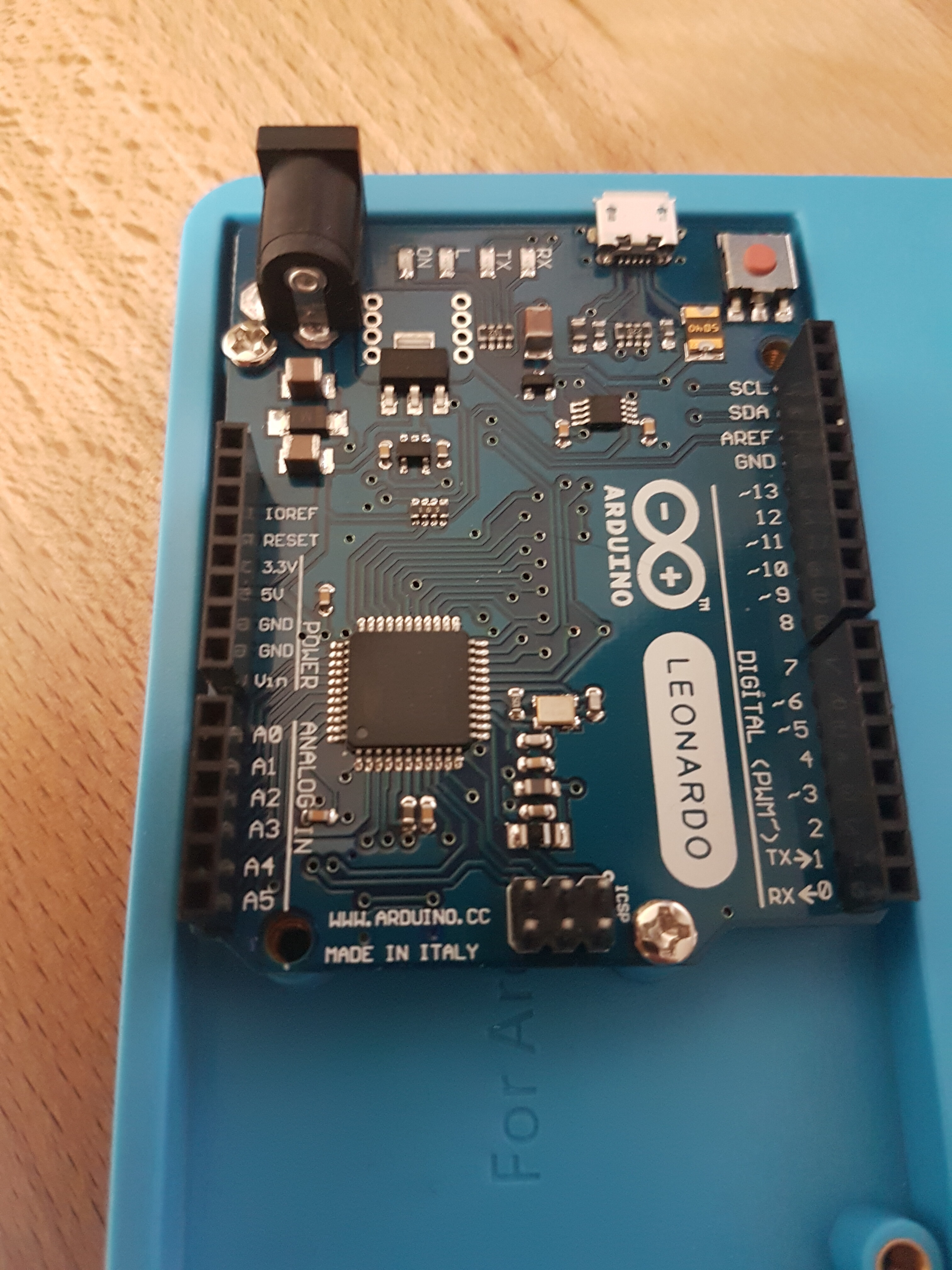
The Y analog, the x analog and the Z analog are to be connected to either A0, A1, A2, A3, A4, A5? it’s up to me to set it up after?
There are two GND on the leonardo card.
So where to connect the black GND and white gnd wires on the board (according to your plan…)
I am a noob in this field
once the wires are well connected, for the parameterization on the arduino, some advices. what do you think about that…
do you think I’ll make it with this information…