CNCjs Joystick pendant

Correct, you can use any of those though I usually try not to use A4 and A5 as those are dual purposed as a special communications line (I2C). If you need to add an I2C device to this particular project later, it’s nice to have them free. On my project I had two joysticks so did end up using all A0 through A5.

  • A0 - X
  • A1 - Y
  • A2 - Z

would be a good setup.

On the board the GND are the same so you can use either one, or both!

3 Likes

Hey @Bwood34,

I suggest you start by using the AlignedJoy library, because:

  1. this is what @mingle used in the code he posted above, so in the end it will be good for you to be familiar with that one
  2. It has a very simple example that you could use to test your joystick once everything is wired:

It’s available here and the code goes like this:

// INCLUDE LIBRARY
#include <AlignedJoy.h>

// PINs DEFINITION
// joystick 1
#define PIN_JOY1_X   0  //(up  down)
#define PIN_JOY1_Y   1  //(left  right)

// CLASS CONSTRUCTOR
// new joystick object
AlignedJoy joystick_1(PIN_JOY1_X, PIN_JOY1_Y);

void setup() {
  
 // SERIAL SETUP FOR DEBUG
 Serial.begin(9600);
 while(!Serial){} 
}

void loop() {
 // for read axis value use "read" method. For x axis -> objectname.read(X); for y axis -> objectname.read(Y).
  
 // print joystick 1 axes value
 Serial.print("joystick_1 X -> ");
 Serial.print(joystick_1.read(X));
 Serial.print(" | Y -> ");
 Serial.println(joystick_1.read(Y));
 delay(500);
}

Which is pretty much the simplest code you can write to use the joystick:

  • one line to include the library header (AlignedJoy.h)
  • two lines to tell the code which pins you used for X and Y. You would write “A0” instead of “0” and “A1” instead of “1” there.
  • one line to create the joystick object
  • the “setup” function present in all Arduino programs just open the Serial console (so that you will be able to see the debug traces in the Serial Monitor window, that you can open from the Arduino environment.
  • the “loop” function is also present in all Arduino programs, and gets called…in a loop, over and over again. In this example, each time it is called it will just read the current X and Y position of the joystick, and display a debug message with their value
1 Like

ok, I will try this in the next few days.
thanks

@Bwood34, just to confirm.

Couldn’t resist, ordered (another) Leonardo, joystick, connected things as per @theworkshope’s image,
uploaded the code above with
#define PIN_JOY1_X A0 //(up down)
#define PIN_JOY1_Y A1 //(left right)

and it works fine (prints out a value between 0 and 1023 for each axis depending on how you move the joystick

I figured it would be easier for me to support you (if you still need it, that is) if I had the exact same setup available.

3 Likes

cool, I did my soldering, everything is ready, but I didn’t find the time to test the thing and set up the parameters on arduino… but I’ll tell you if I need to.
what are the leds for?

Nothing. That’s what happens when you grab a breadboard from the last project, and you are so lazy you don’t even bother cleaning-up :rofl:

2 Likes

Are the bits of wire insulation left over too? :stuck_out_tongue:


it’s ready… I have to test it, but not before next week… no time this weekend.

2 Likes

the white wire is not connected?

That’s the Z axis and the example code I showed does not read it. Easy to add afterwards.

This is what happens when I realize it’s 10pm already, I have a few minutes of shop time left but I want to get this done anyway, so I grab everything, start-up the soldering iron, solder solder solder, plug usb, load code, run, post about it, and doooooone. If I could buy time, I would. :sweat_smile:

2 Likes

we are all the same here… we work until 11pm…
I did my welding on Tuesday night :wink:

1 Like

It looks great. I will definitely try to build one myself. I already have the leonardo and the oled display. I will order the joystick and the mpg but I have tested the arduino code with a simple 2-axis joystick and a rotary encoder and I can see in the serial monitor it’s working fine. Could I get a 6 terminals mpg and connect only 4 of them or I should get a 4 terminals mpg?

I’m not familiar with the cncjs code (haven’t tested yet the pendant code) but I could help with the arduino code and I might rewrite some functions to match the hardware I have in mind.

The display will be on for both modes showing what is active. I don’t want to use the mode selector switch. I’m thinking to use the joystick button to enable joystick mode, and then use either the axis button or step button to enable mpg mode. I want to add as much buttons as my board (pro micro) allows to add more functions (home machine, zero selected axis e.t.c). Would that be possible to add functions like connecting to the machine, probe Z and other macros?

2 Likes

not sure about connecting to the machine, but anything that executes G-code (macros) does work, as the CNCjs pendant interface basically allows one to talk to the machine directly. I implemented smooth jogging that way:

1 Like

This topic was automatically closed after 29 days. New replies are no longer allowed.

FINALLY some progress, it’s alive:

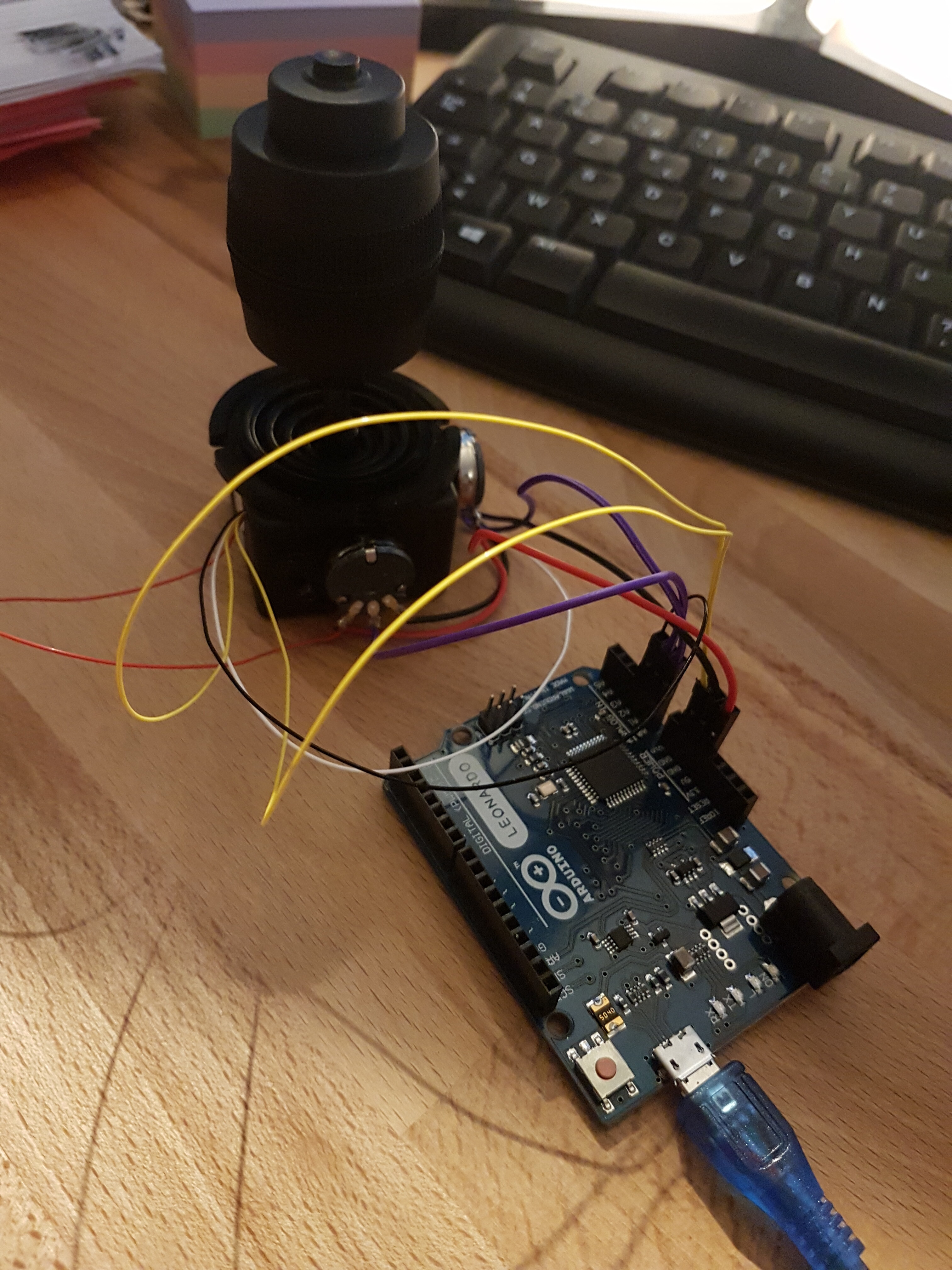
I restarted from @mingle’s code (thanks! experimental as it may be, it saved me hours of effort), and customized it for my setup.

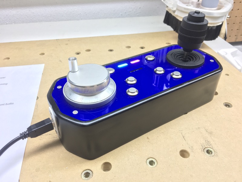
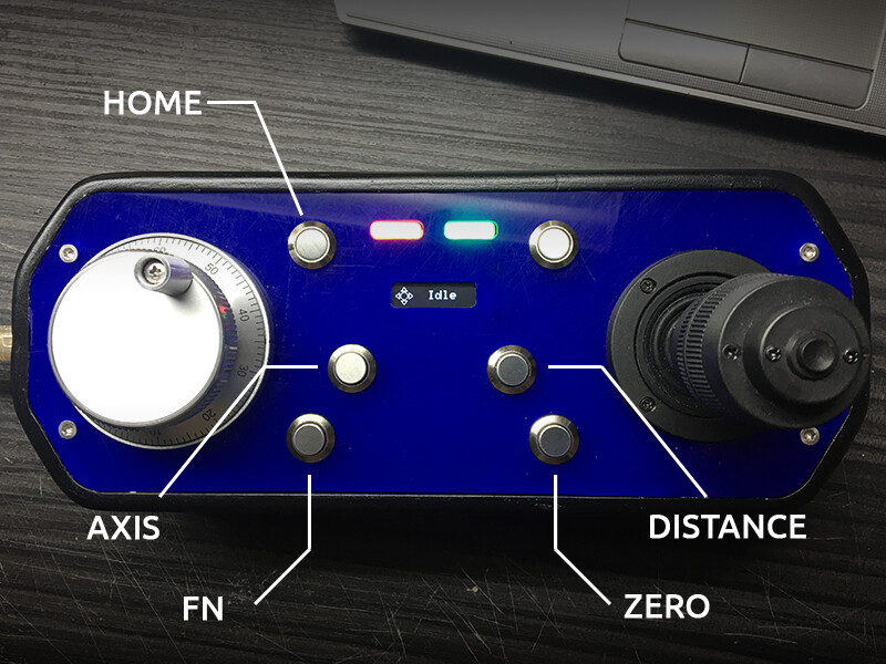
I added the management of the joystick Z-hat/button, it now acts as a safety enable for joystick movements (because eventually my joystick box will be located at the front right of the enclosure, and I wouldn’t want the machine to start moving if I hit the joystick when leaning into the enclosure)

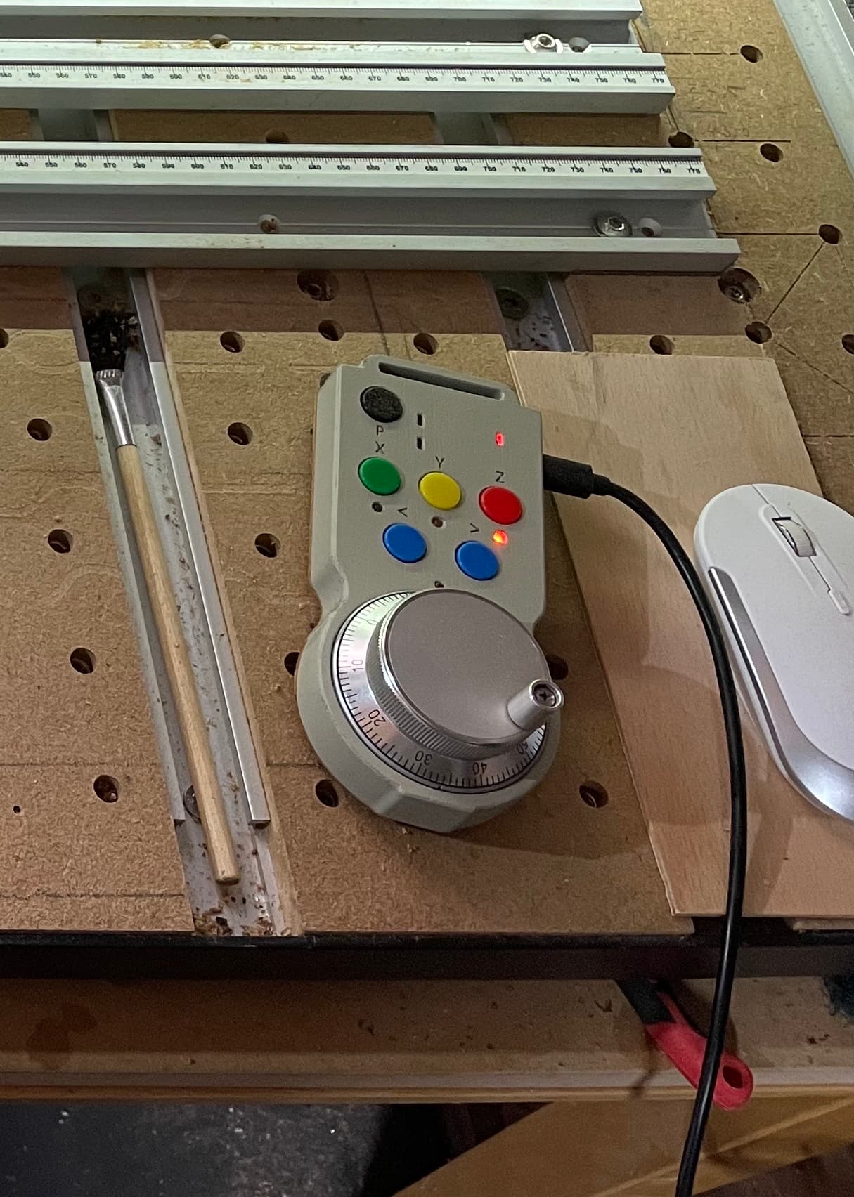
The buttons on the right are used for X/Y/Z single step, and the top three buttons allow to select between 1mm, 0.1mm, and 0.05mm steps (which is all I ever use in the CNCjs interface anyway)

I’ll probably tune the delays and steps to smooth the speed variations (which can be heard in the somewhat funky jogging noises), but I think I’m hooked to the joystick as a jogging device. It feels much more natural to me than all keyboard-based jogging solutions I experimented with previously. And since I moved from the SO3 to the XXL, the importance of being able to jog quickly to any location matters a lot now.

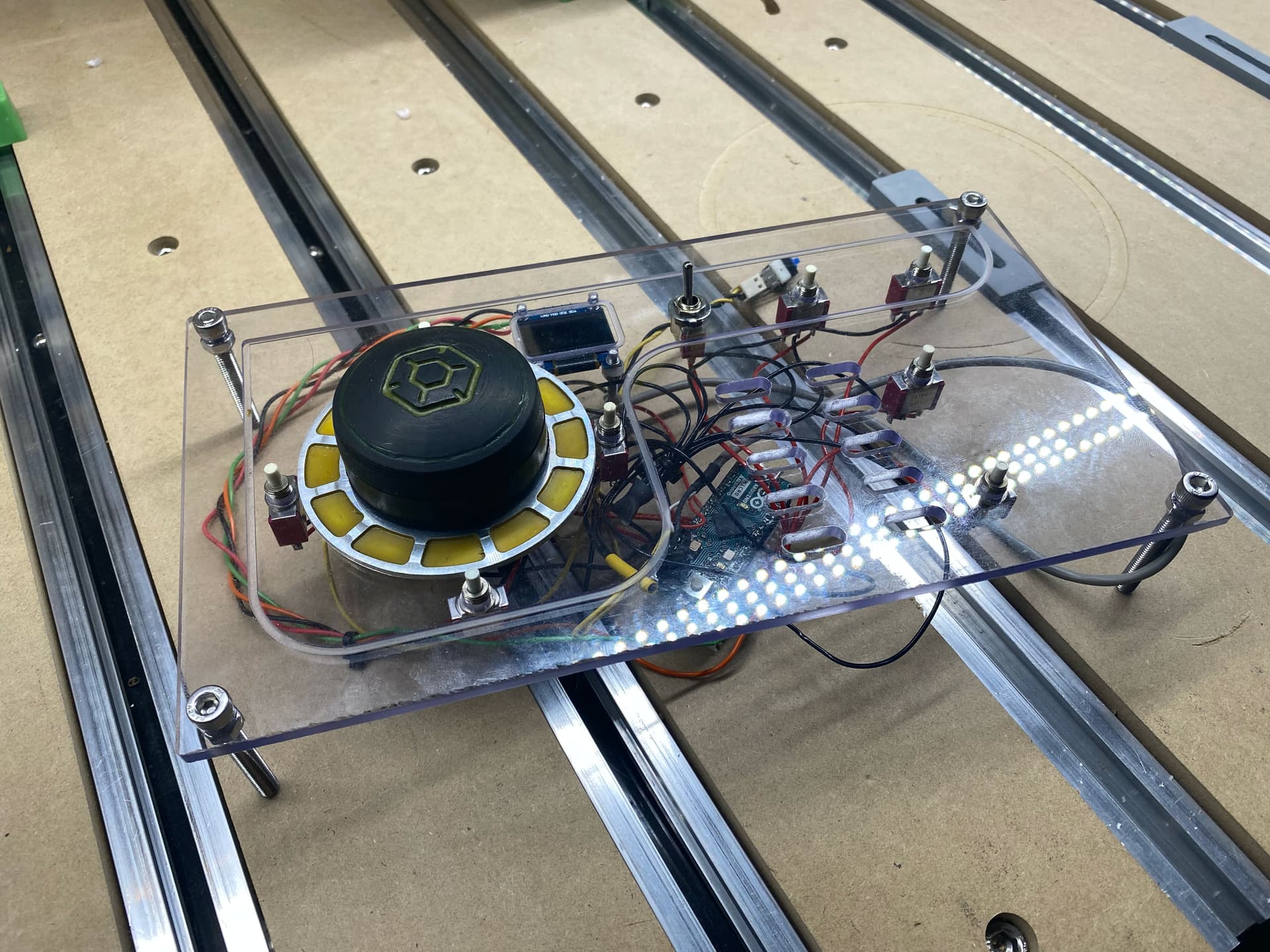
Note1: the 3D-printed case for the small OLED display was only supposed to have it at an angle for better visibility, somehow it turned out looking like a mini iMac or something, which looks cool so I did not bother printing a less bulky version.

Note2: I used an Arduino Leonardo since I initially wanted to emulate a keyboard, but at the end of the day a plain old UART (that can run on any Arduino) like @mingle did is much better, as one does not have to care about window focus then, the CNCjs pendant just runs and listens to anything coming on a specific COM port, regardless of the currently active window.

Note3: still, the Leonardo will come in handy if I want to use this setup to control Carbide Motion via keyboard shortcuts emulation. Right now it’s a CNCjs-only solution.

8 Likes

I went down the USB/Keyboard emulation route, @Julien, and have a dial-based jog pendant which like yours has become indispensable in use. It will work with any Sender app that can have keyboard shortcuts, and any host OS (Pi, PC, Mac). I would argue that second only to the HDZ, the pendant has been the best addition to my 3XL. I designed a housing, mini-PCB to hold the switches and Leonardo etc., wrote the Arduino software such that I could experiment with switch de-bounce ideas (settled on integrator/numeric settling), and so I could include rotary axis control in such a way that the static axis (Y in my case) can’t be nudged in error once aligned with the chuck axis.

Using mine with UGS (so I can have the visualiser graphic, and also 5-axis numeric display) works really well, and only occasionally do I suffer from the ‘jog keyboard’ losing input focus. The Mac just beeps if this happens as I have chosen keyboard commands that can’t accidentally cause some other action if focus is lost. I might experiment with Lua Macros to see if an embedded pendant function is possible, in which case I have the best of both worlds. One for another day, I have a rotary axis to play with now :slight_smile:

6 Likes

I finished mine a few weeks ago. It’s also based on @mingle code but I have made a few modifications especially on the Arduino code.

The joystick stops transmitting data when it’s idle. That way the buttons work only when the joystick is idle.
There are 6 buttons + joystick button.
Joystick button: switches the mode from MPG to Joystick.
FN: acts as function to add alternate commands to each button when it’s kept pressed.
AXIS: switches from Joystick to MPG mode. In MPG mode it switches the selected axis between X and Y. It enables Z if FN is pressed.
DISTANCE: same with AXIS. Decreases the selected distance. Increases if FN is pressed.
ZERO: in Joystick mode it sends G10L20P1X0Y0. In MPG mode it sends G10L20P1x0 where x is the selected axis. With FN pressed if selected axis is X or Y it sends X0Y0, if it’s Z it sends Z0.1. All of these could be easily change in the Arduino code.
HOME: sends $H or G53G21X-50Y-50Z-10 with FN.
EXTRA BUTTON: not assigned to anything yet.
I have added two ws2812 LEDs which show which mode is enabled (MPG or joystick). I could add more functions to the LEDs later.

I had to experiment with joystick.js to find the best values for my machine. My machine is homemade and it’s not very fast. I was changing manually the values in this equation: step = v * dt; until I found what is the best step for my machine. Then I calculated what should be the MAX_SPEED to achieve that step and I experimented with SMOOTH_JOG_COMMAND_INTERVAL to have a smooth result. It might need a little more effort but I’m happy with the result.

If you need them I could share the edited files and my Arduino code.

11 Likes

Disapointed in myself right now for not reading this thred throughly the first time, but thanks for the video´s all of you. I´ve spent &"%#$"%$ hours browsing for backdoors into CM and UGS to find faster JOG interface than keyboard emulation. The @mingle method seems great! Now I need to test CNCjs… If anyone knows any alternative ways where motion program is still able to track position during jogging (while at the same time showing it on the screen), then please share.

As a break, I decide to put more effort into the GUI on my side for the moment as I temporarily need a break from the annoyingly slow respons in CM.

Sorry, I read that twice and I can’t tell for sure what this means, can you please elaborate ? (on the off chance I may have an option for you based on my own tests)