For bugs, we would prefer that folks just mail them in to support@carbide3d.com — include the .c2d file, and a screengrab showing the selection state in question and provide clear step-by-step instructions for causing the problem and we will do our best to look into it.
Yay, I look forward to seeing this and using it. Like others, I’m sure, I clicked through the options to trim the vectors hoping one of them is the one that works best. Thank you for implementing this.
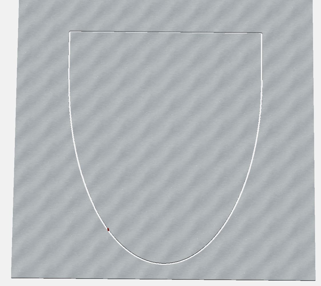
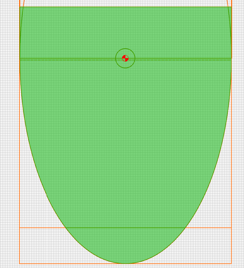
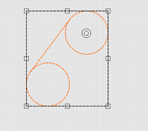
I just had my first “real” usage of the Region Builder and it made my life SIMPLE. I was just creating a template for cutting an oval table top (62"x31")…I won’t be cutting the whole thing on the CNC (because I’d rather not deal with the tiling…and frankly using a pattern bit with a template and a handheld router is faster. But I wanted to create the template with the CNC out of 1/4" hardboard. The template was a half-oval with squared lead-ins on both sides (for alignment and starting/ending points for the pattern bit. I ended up with this:
Adding my thank you for this improvement. I have struggled with trimming vectors and this made a project I was working on so much easier. Thank you thank you.
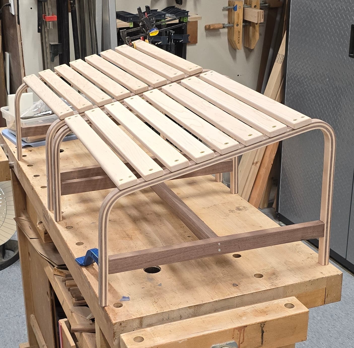
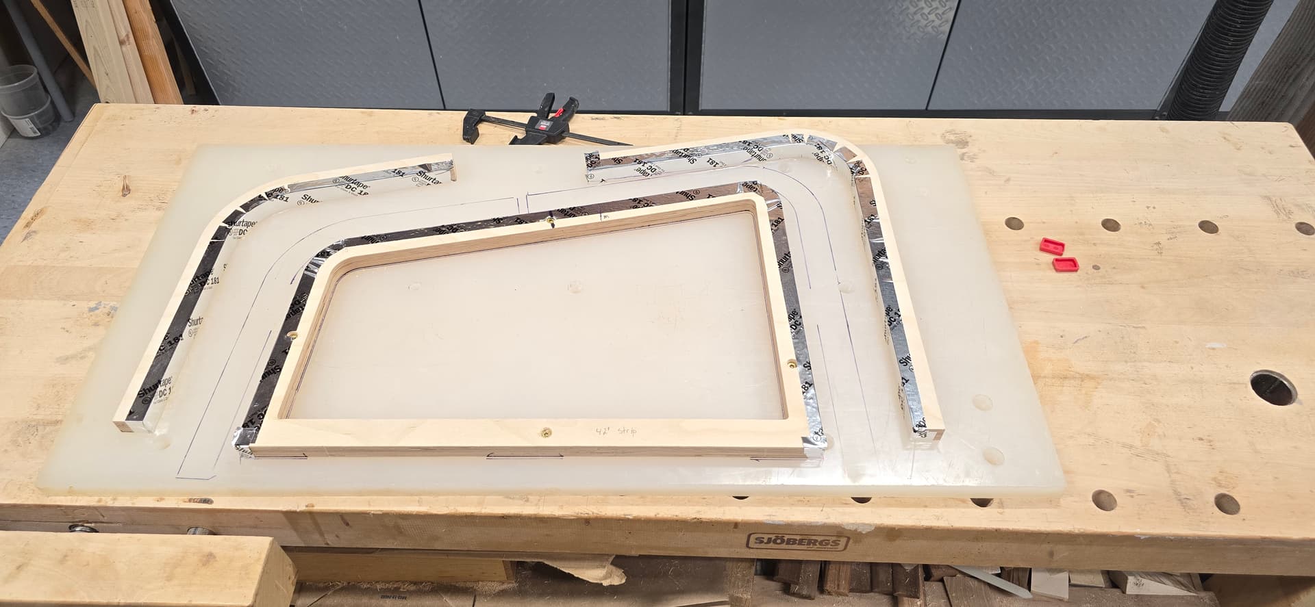
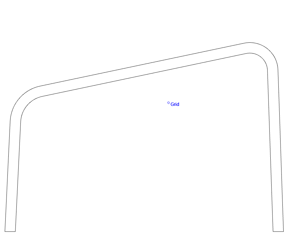
I recently struggled to make a steam bent wood forming tool for an Adirondack chair footstool. The concept was fairly easy but figuring out how to draw the outlines to get to the toolpath drove me crazy. This is what I ended up with but had to use several packages like inkscape to do it. I’ll go backwards from the completed project or it will be hard to follow. This is the completed stool.
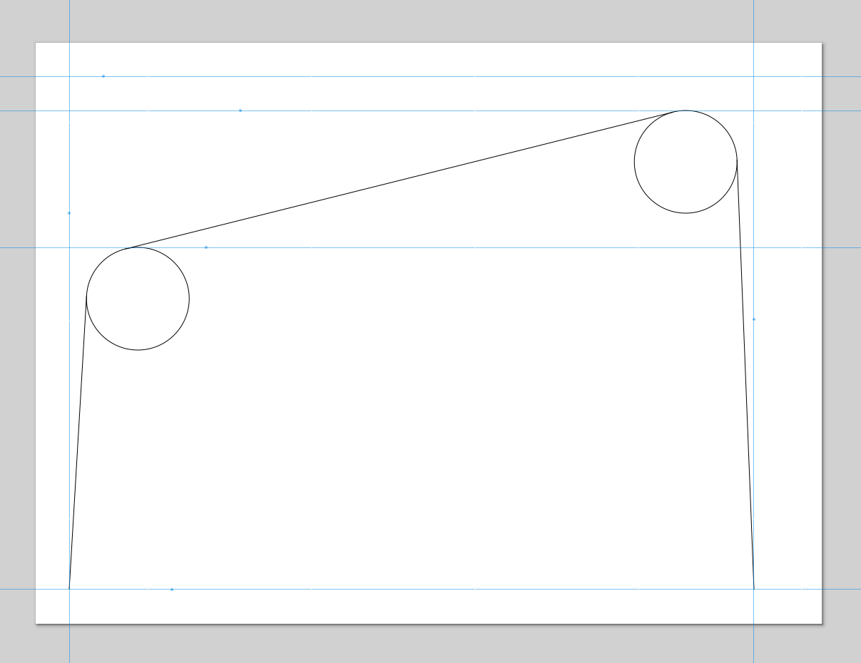
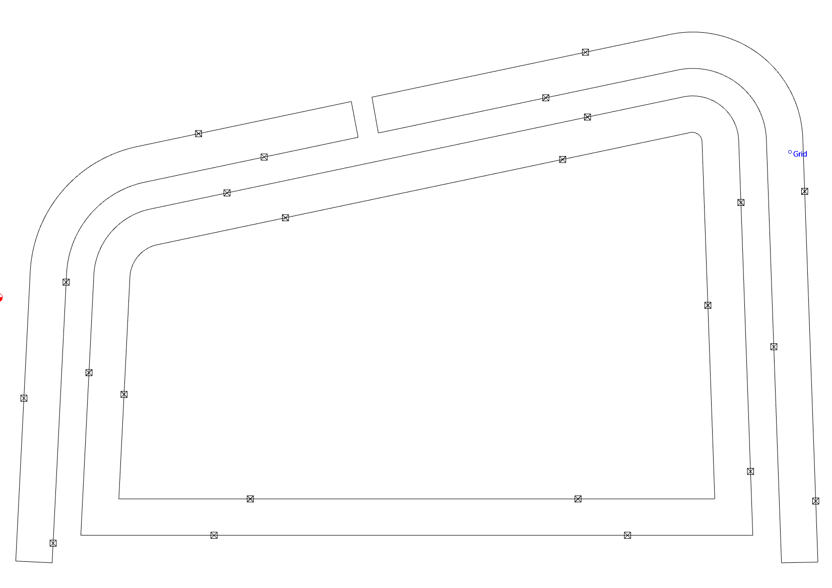
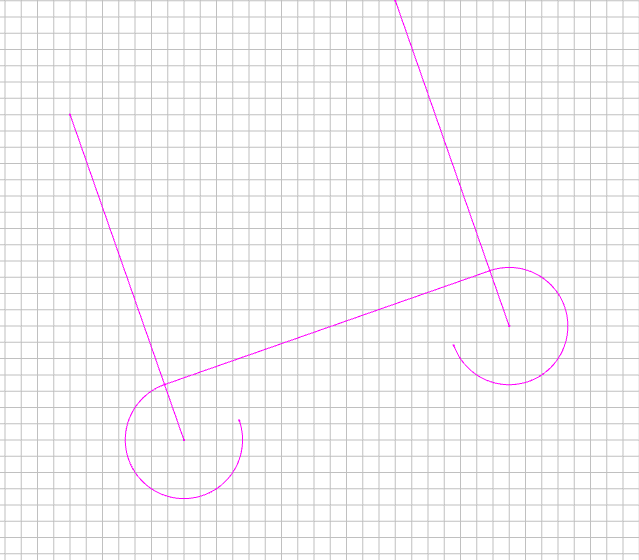
This took me hours to figure out how to get tangent lines to intersect circles and then trim them back. Then I had to make offsets for all of that and trim those back.
I finally got there but it could have been much easier. Years ago I was selling a $10K drafting software package from Hewlett Packard called ME10. It had a super simple concept of “drafting lines” and “geometry lines”. Sort of like my “sketch of outline” picture which is a little similar to this new vector trimming. All you do is use various 2D drafting tools to draw lines, circles and other boundary condition geometry and then you enter the “geometry line” mode and click on the segments and nodes you want to turn into the final geometry. You could click on a circle and it would draw a line on top of the circle until you got to the intersection you wanted and you click o that. It is similar in concept to the new functions but many times you don’t have completed enclosed geometry or there are several options to pick from. Just a suggestion. Happy to provide more info if needed.
What you describe should be pretty easy to do using Trim Vectors (remove geometry which is not wanted) then select what is wanted and join it. If you have difficulty with anything, let us know and we will do our best to assist.
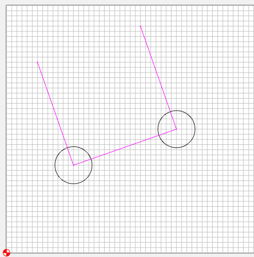
I do like trim vectors and use it a lot but I couldn’t get it to work with tangent lines. Look at the “Design concept was simple” picture. I created those lines in inkscape since I didn’t see tangent line functions in Carbide Create. Is there are way to do this in Carbide Create? If so I would love it. I teach a steamed bent wood fly fishing net class and deal with a lot of tangent situations.
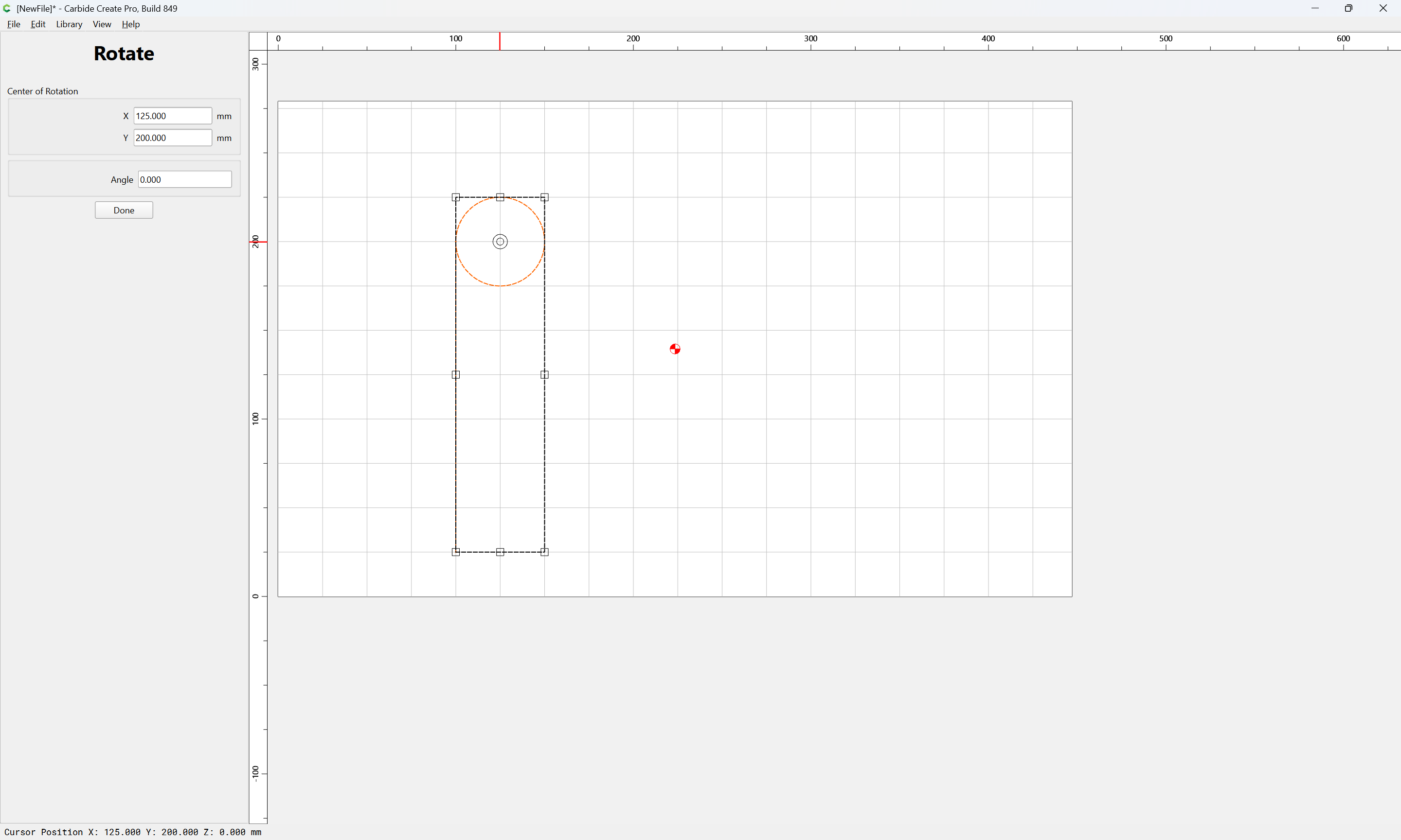
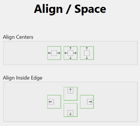
If you can create the circles on an axis (x or y) and draw a line between the centers, then you can move that line to the outer edge with the alignment tools, group them together, and then rotate around the center of one of the circles. Might be a bit easier than trying to go back and forth between the edges…
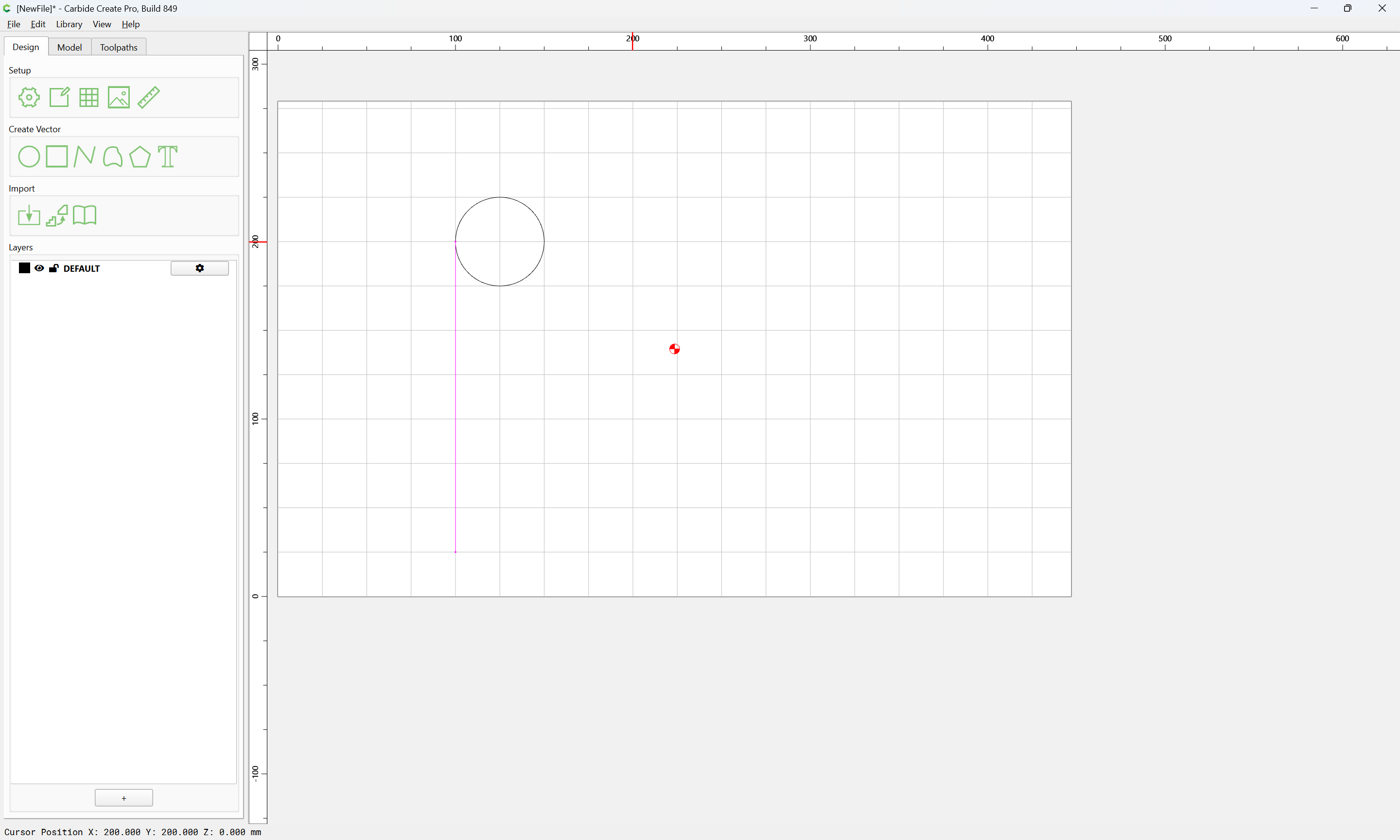
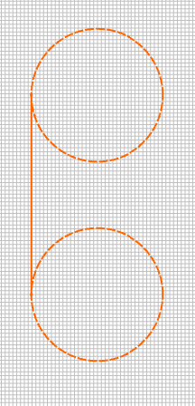
Here’s how I did it:
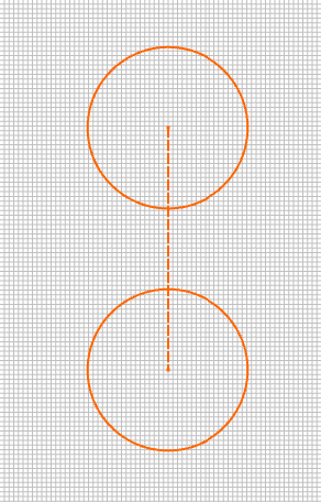
Drew the two circles (I used the linear array with 1 column and 2 rows to ensure centers aligned…and to place the two circles the ultimate desired distance apart (after rotation)
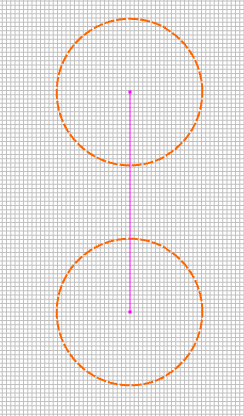
Then I connected the centers with a line (you can see “Center” when your mouse is over it)
If you have 2 randomly placed circles, draw a line between their centers, copy the line twice & rotate 90°. Place one rotated line at each circle center