This sort of thing is discussed in:
which I’d recommend to anyone interested in this sort of thing.
This sort of thing is discussed in:
which I’d recommend to anyone interested in this sort of thing.
Fiddling with the design and making test pieces to try different woods and feed/speeds probably took 4-6w of ‘some evenings’, But part of this was learning Vectric vs CCreate. The main cutting took probably 2w of evenings etc, then re-made some of the gears after reading up on tooth profiles, friction and backlash to help the clock run smoothly. Building and refining the basic running another week or so - still have to do the day job… Thinking of the Raspberry Pi construction then laying out and waiting for PCBs to arrive and build was 2-3w. Bringing it all together, then looking for the inaccuracies and wheedling them out seems to have been a never-ending game. So 2.5-3 months in all, interspersed with other distraction projects
Gear-O-Graph
Challenge is a good way to categorize this one. I am not a Mechanical Engineer. I know enough about gears not to smash my finders. SO, what to make for this months challenge? Believe it or not, I was considering a clock. It would have taken me a year to do what Andy did. I also considered (and will try in the future) a kinetic machine. The professional ones are AMAZING!
I even considered a marble roller coaster for a little while…
But, to stay at my skill level, I settled on an inspiration from thingiverse
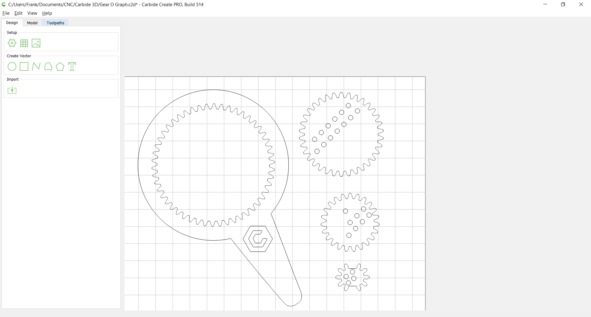
I took on what I call the Gear-O-Graph. I followed Julien’s example and used the Planetary Gear Designer to come up with the layout. I deleted the parts not needed and used Carbide Create to design.
 teeth.
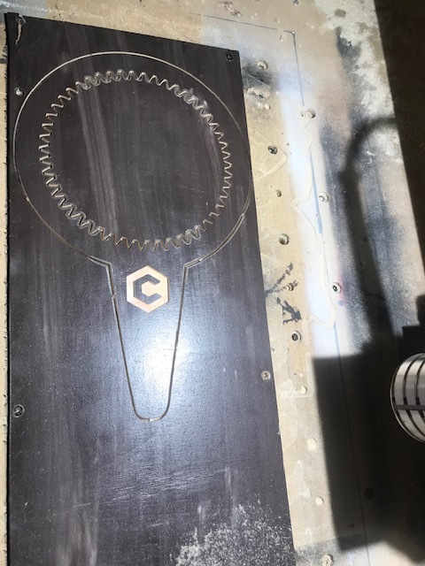
Start over with quarter inch birch ply and the handle came out pretty good
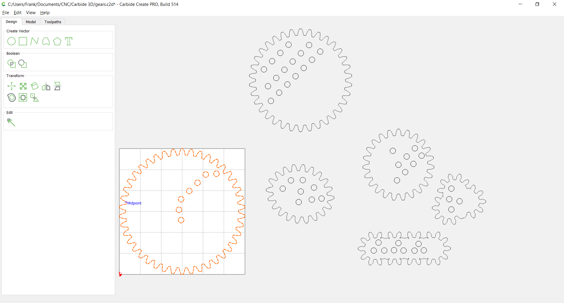
On to the gears themselves. I tried a few designs and will go back and try more. Circular is easy enough for a design test, so that is what I cut today.
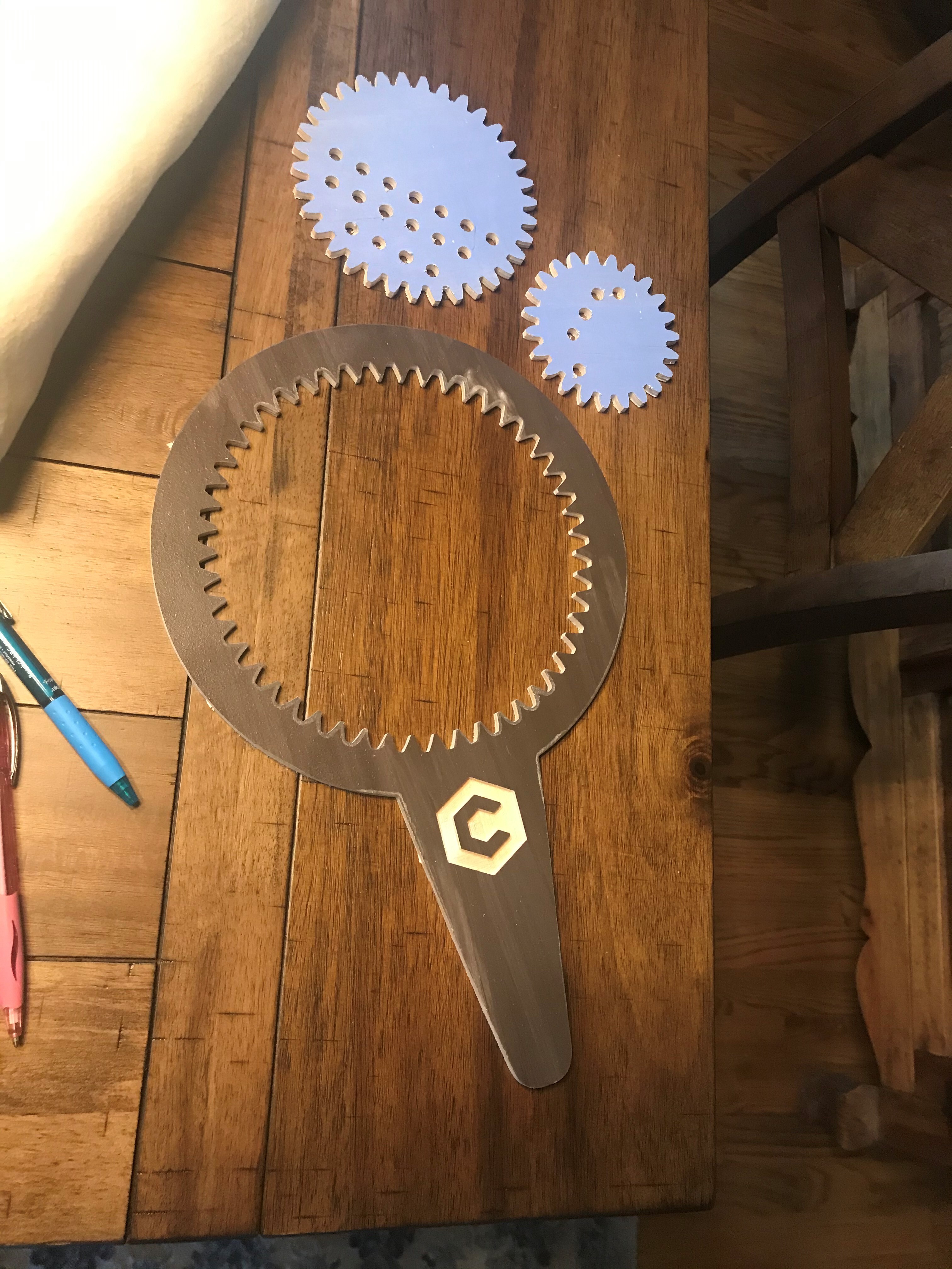
Birch ply again and the holes are a little large, 1/4". Good enough to test…And final cuts from today.
I’m sure this can be greatly improved upon but learning is the point…right? Files:
Gear O Graph Handle.nc (1.5 MB)
Gear O Graph.c2d (3.3 MB)
Gear2.nc (644.9 KB)
And Cutrocket: https://cutrocket.com/p/5f8f968ddfff1/
(Note: Uploading to CutRocket not working properly. I was not able to add pictures…)
Hi Franck,
Thanks for your entry and bringing back childhood memories!
Making a wooden CNCed spirograph is so much better than buying a plastic one, I’m sure some will benefit from your sharing those files to make gifts for their kids/nephews.
Great Job Frank, that is really cool!
Thanks, Mike. Keeping it simple.
Design would be better in plexiglass like you did. Maybe I’ll try that soon
I had already built a Planetary Gear, and was trying to find a way to reuse that design in another project.
Then a long-time friend asked me to help him build a PC for his kid for Christmas. By “help” what he actually had in mind was to order the parts and have them shipped to my house. The parts will slowly trickle in between now and Christmas. I already have the case he picked out. So while I’ve been waiting, I’ve been thinking up ways to design something on the CNC to make the computer really unique.
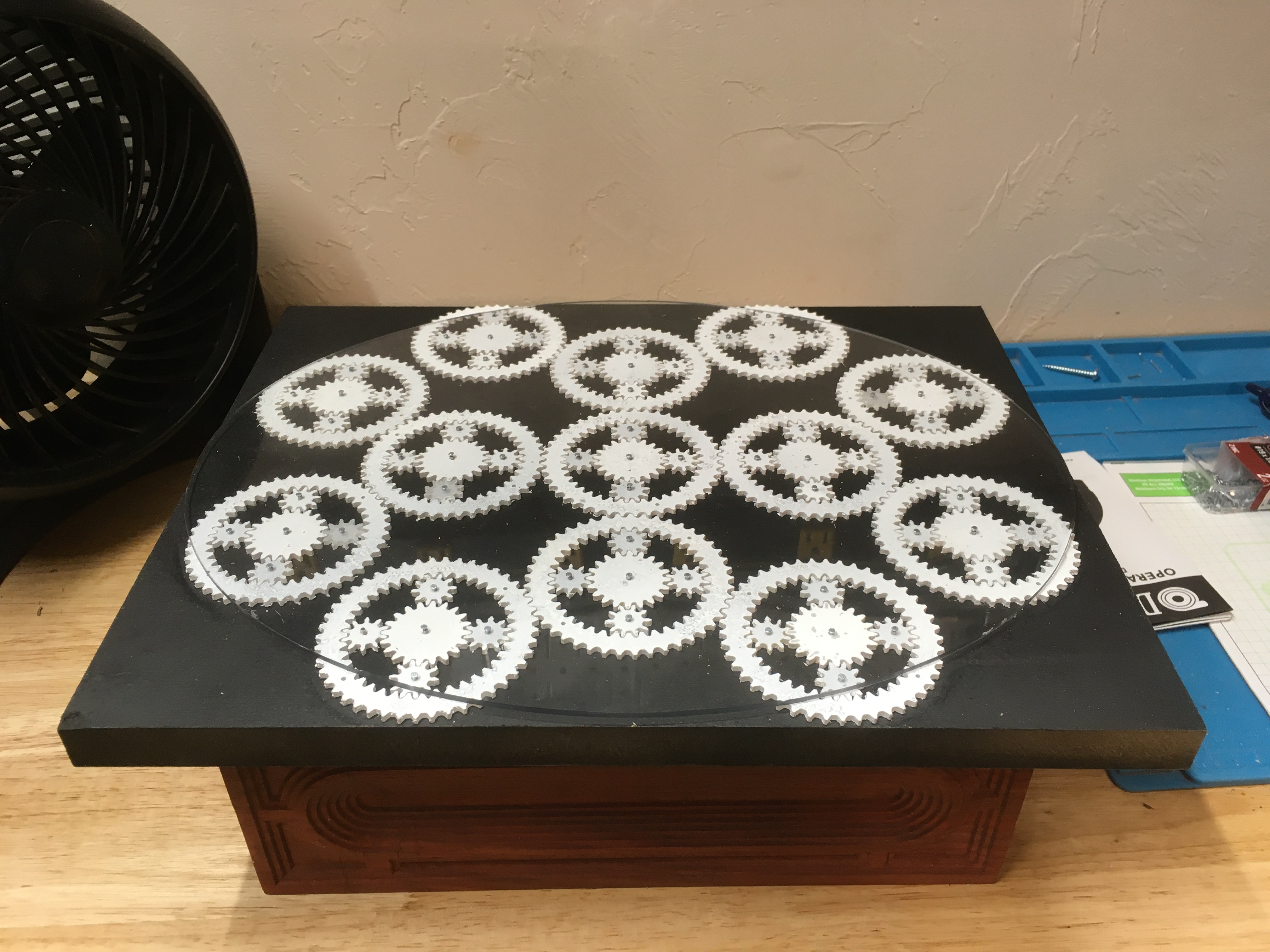
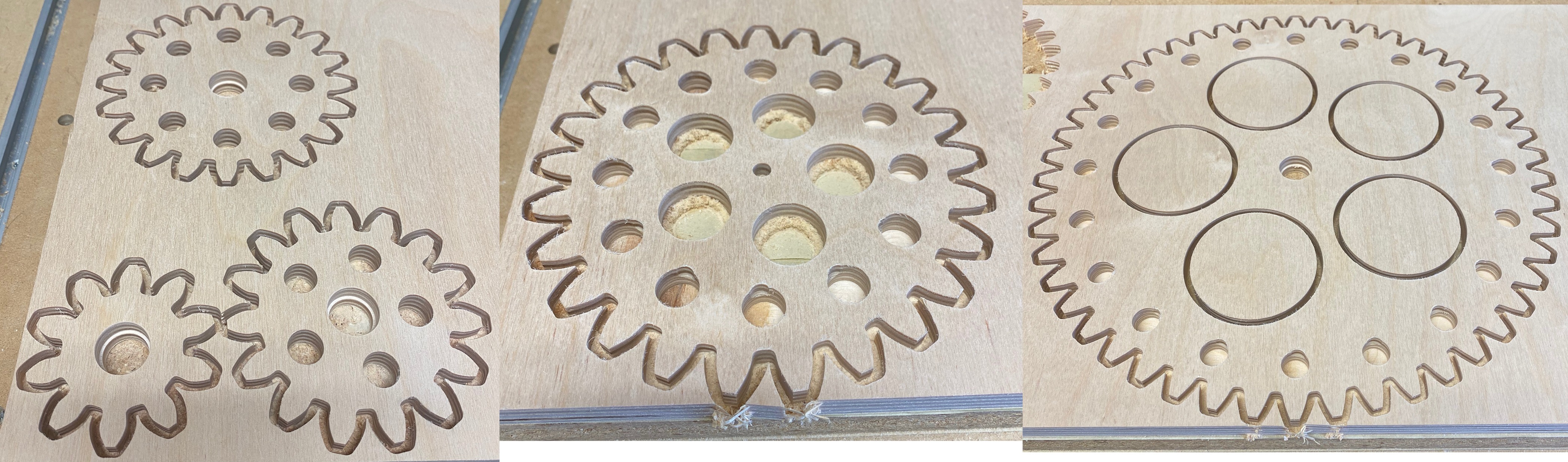
The color scheme on the computer is going to be black and white, so I used lexan and my Shapeoko to make 13 planetary gears that fit/spin together. Kind of a Stormtrooper / Steam-Punk mash up. It looks busy, but doesn’t actually do anything, like a politician.
I first laid everything out in Carbide Create, to see how the gears could fit together, and used this to cut a template (for assembly). But what you are seeing is just the initial concept, I’ll rearrange the gears in the computer once the computer is fully built. My goal at this point is to get the gears cut out and ready.
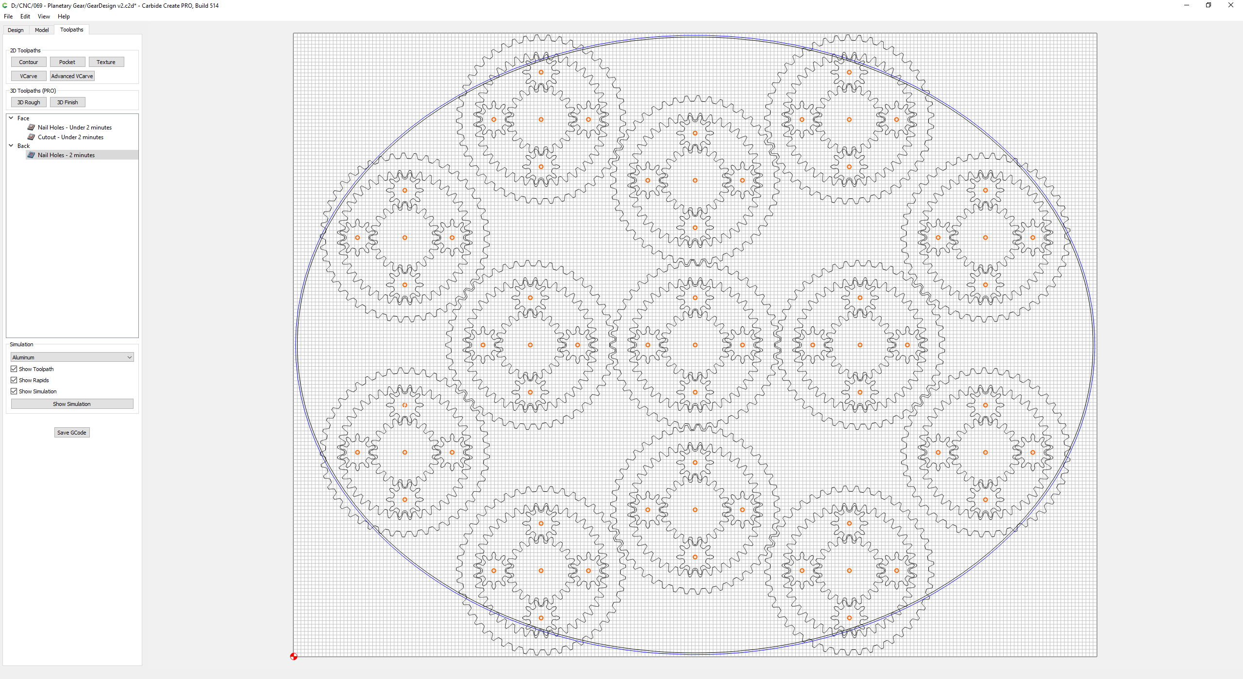
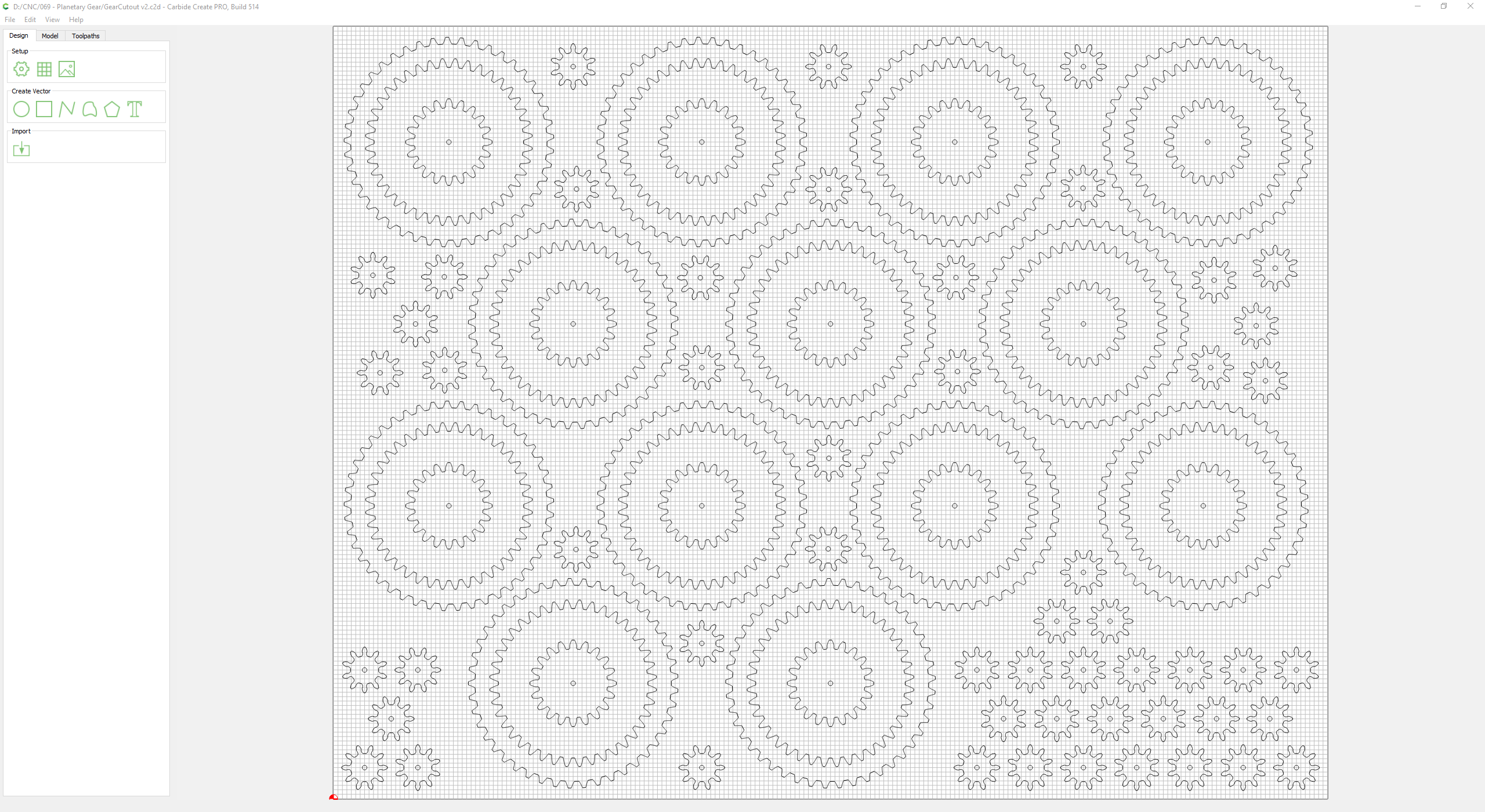
I took that Carbide Create “GearDesign” file and did a save-as so I could rearrange the gears in a way that I could cut out each individual gear. I already had 14x11 sheets of Lexan (Polycarbonate) and was able to cut all 78 gears (and a few extras) from a single sheet.
I used the #112 1/16 endmill, 1/32 depth per pass, 100 in feed rate at 10,000 rpm. This cut the polycarbonate cleanly, without any melting.
I used small, smooth shaft nails for axles and another sheet of lexan with just the nail holes drilled out (from that GearDesign file) to assemble this useless machine.
A fun project, that actually works, but now that I see it I’m not sure it fits with the computer design. Looking at @AndyC clock design, wow!!, yea think maybe I should start over.
The Carbide Create files are 33MB each. 25MB zipped, way to big to share here. Not sure what I did to make the files so large, but I basically took the single planetary gear design and made 13 copies.
Planetary Gear.c2d (2.9 MB)
That PC case is going to be one of a kind !
I can’t quite see on that last pic, do you plan to add pins in every hole, and then have some way to rotate the outer gears ? (maybe that’s the reason for making the acrylic part a bit smaller, so as to be able to turn the gears manually from “the outside” ?
Imagine integrating a small motor that would spin that central outer gear very slowly while the PC is turned on, spinning every other gear in turn…how cool would that be?! That and some obligatory subtle LED backlighting?
Every gear has a hole, and nail/axle (so 5 per planetary gear). I’ve bookmarked a few 12v 1rpm motors on amazon, but not committing to anything until I know what the pc is going to end up looking like. At this point I think the design is too flat, one dimensional. Looking at @AndyC clock and how the gears are stacked, that is the direction I want to take this, even if it results in giving up the gears actually rotating.
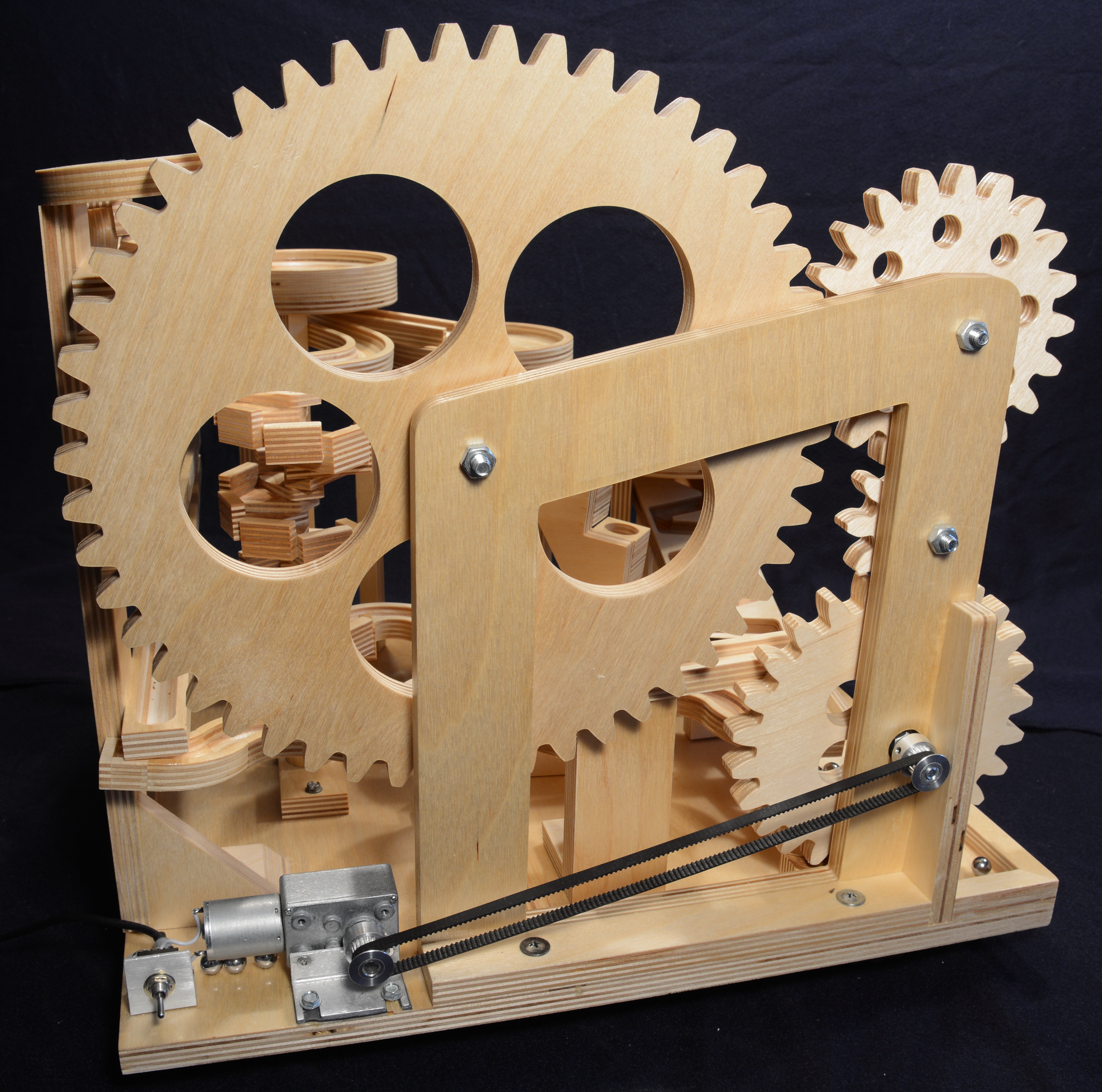
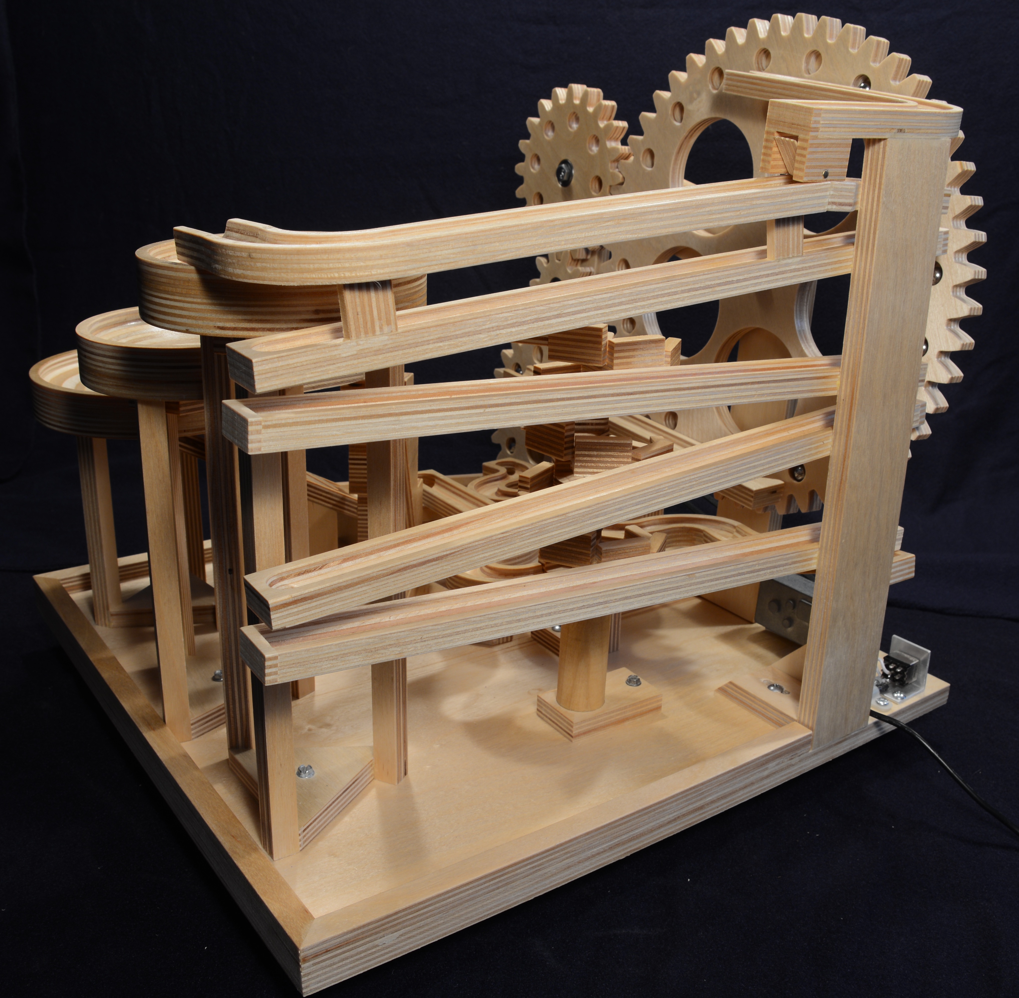
MARBLE MACHINE
Photos don’t do it justice - please watch the video, with sound ON!
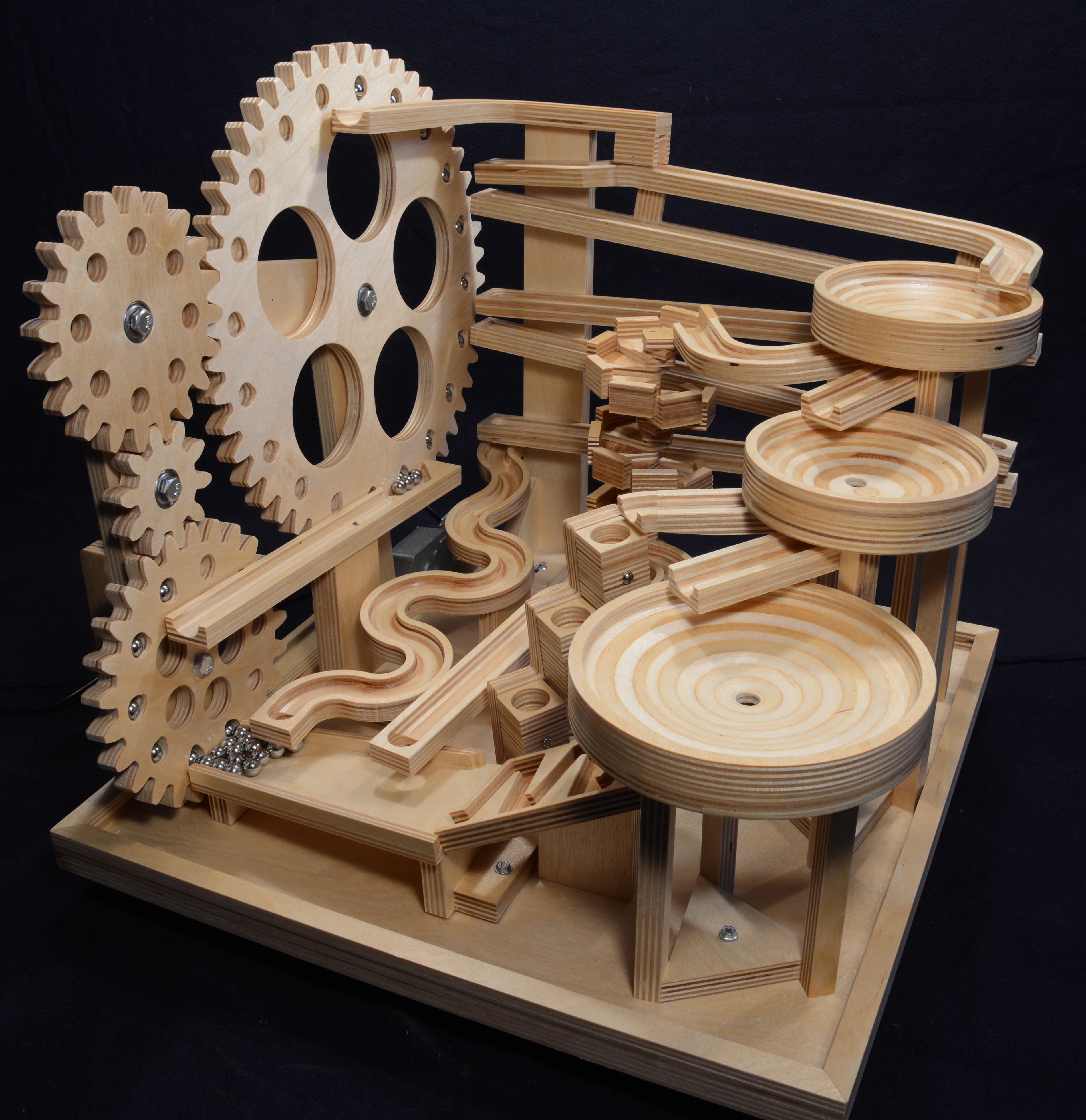
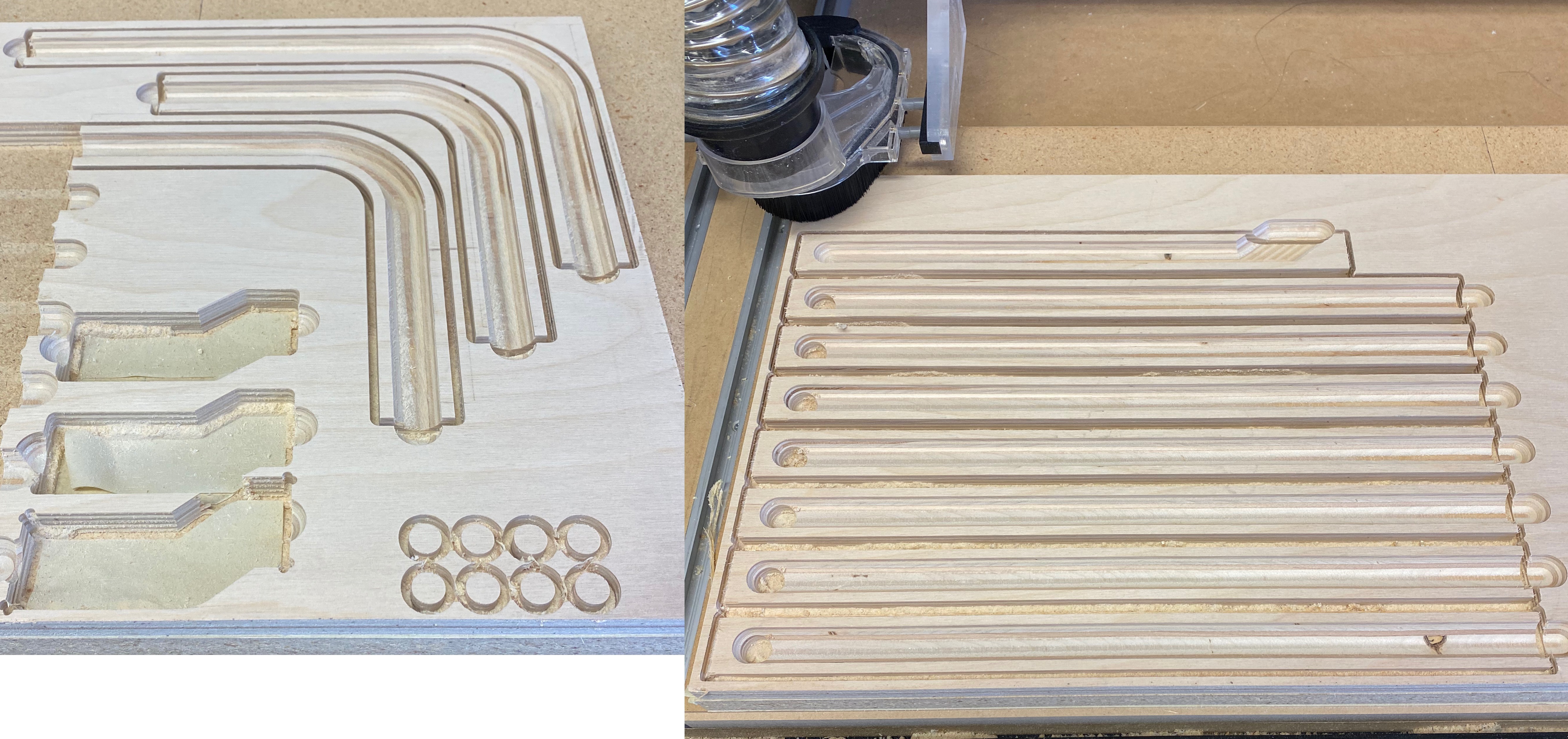
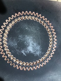
The hardest part was getting the marbles to load, not fall out on the ride to the top, and then dump out consistently at the top. Gravity keeps them in place for the ride, because the gear rack tilts back 4 degrees. Then through trial and error I machined “divots” on the inside edge so the marbles fall out at the top. [Note: The “better” way is to drill the marble holes on an angle with a Forstner bit in a drill press. But who wants to use a drill press for 30 holes when they have a CNC???]
I had no particular plan. After successfully getting the lifter mechanism working, I just made it up as I went, adding on stick-by-stick until all paths led back to the start.
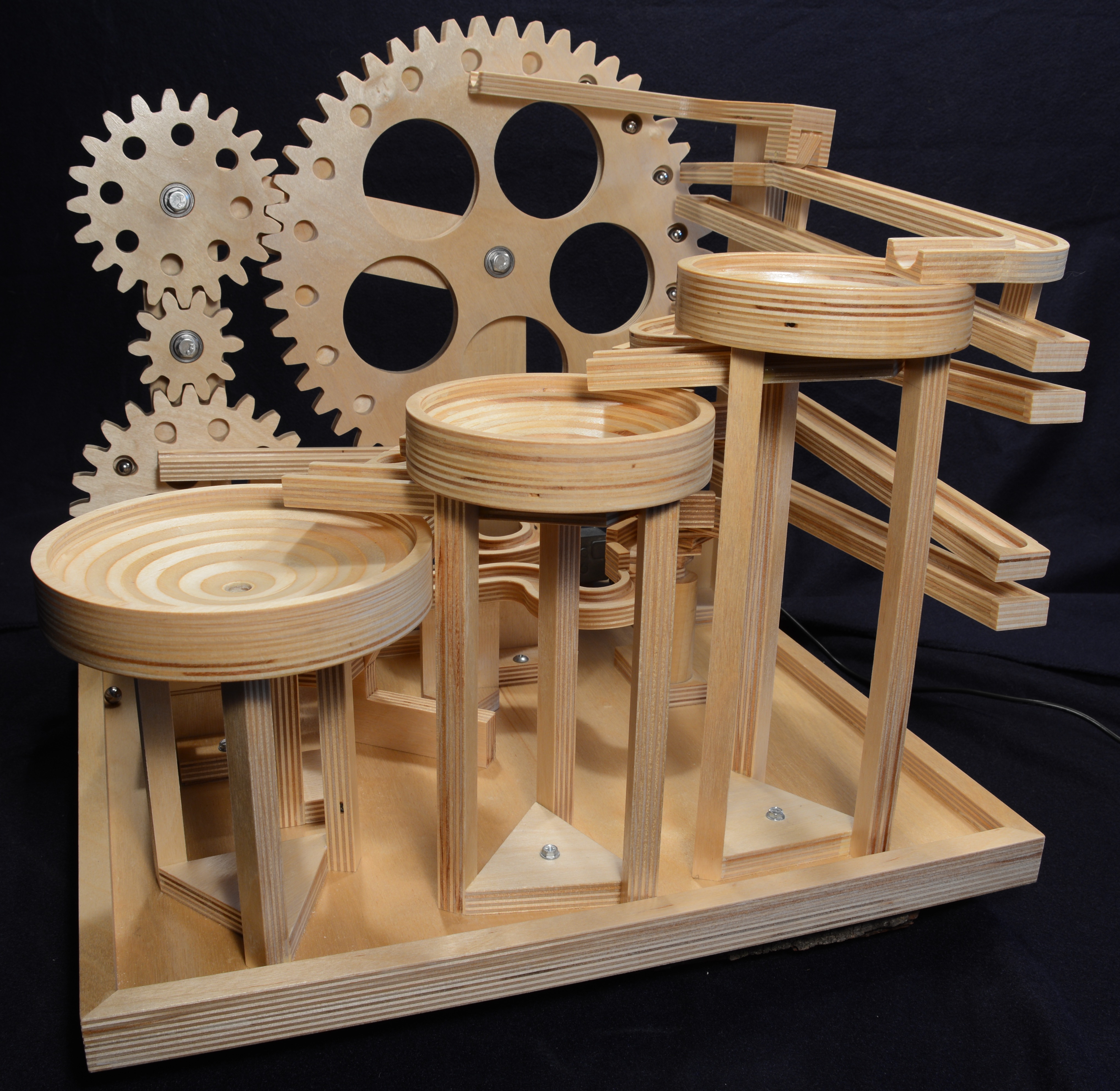
FINISHED PROJECT PHOTOS
DESIGN NOTES
THINGS I LEARNED
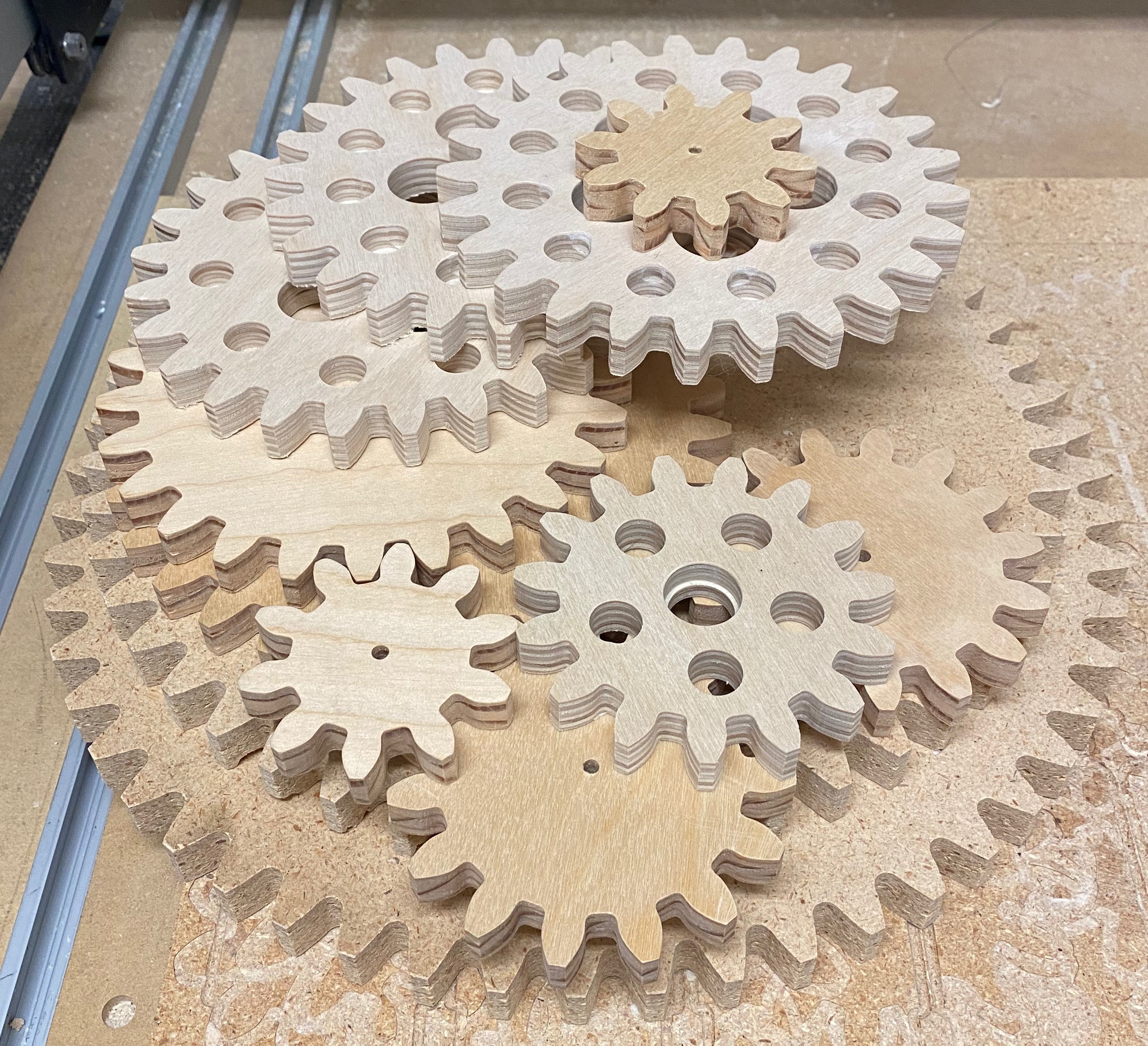
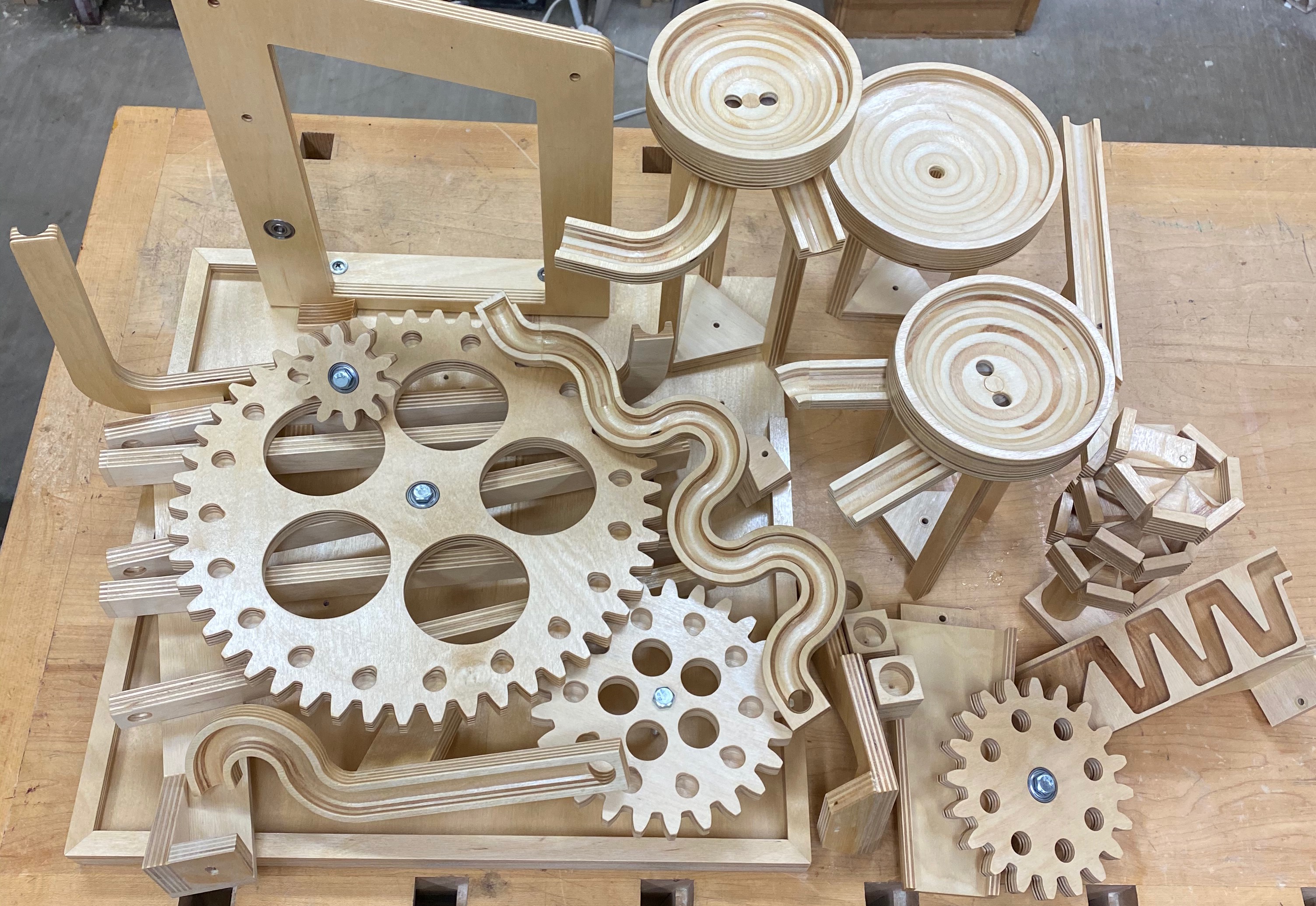
THE BONEYARD, a.k.a “THE ISLAND OF MISFIT GEARS”
Prototypes, extras and mistakes:
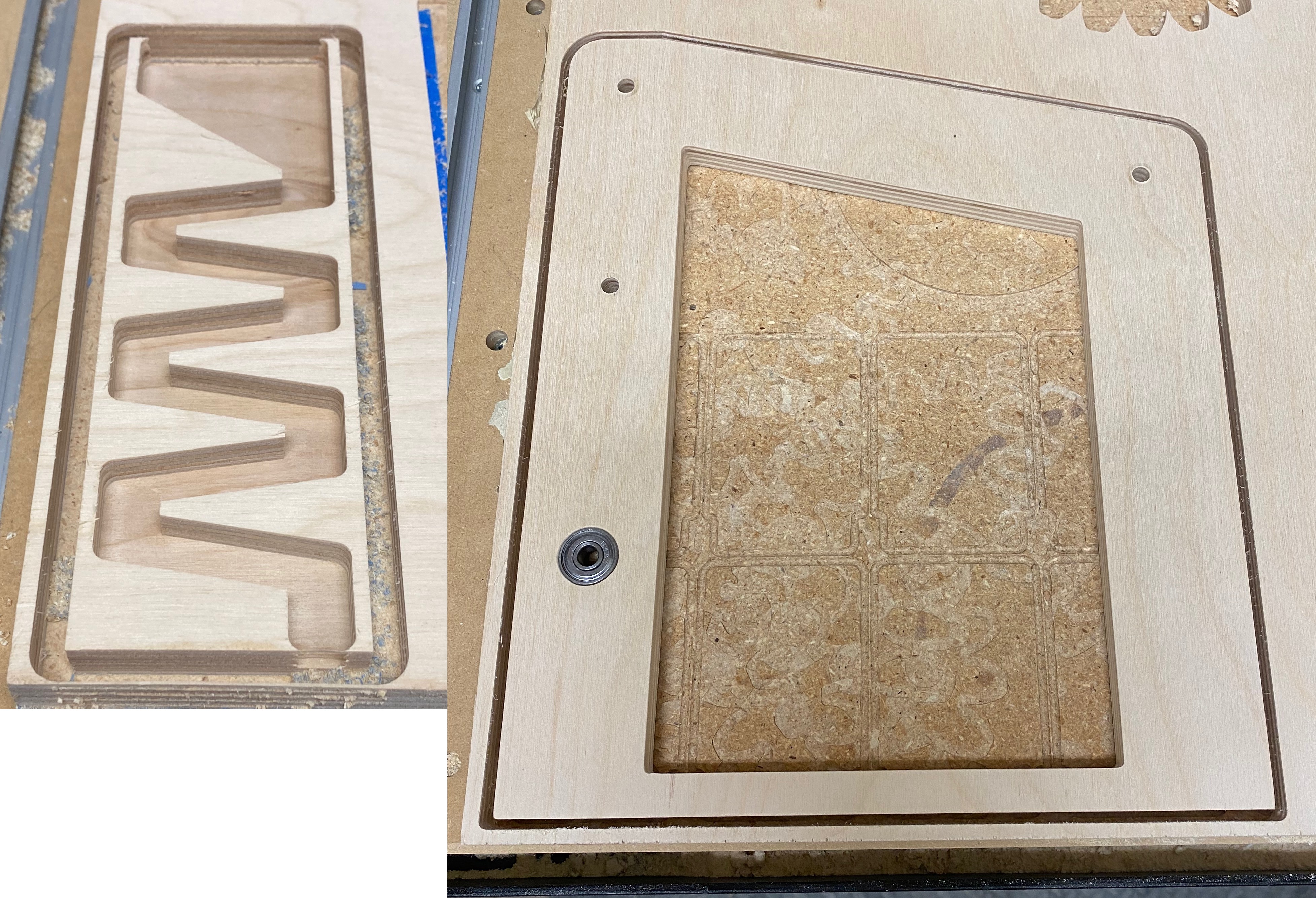
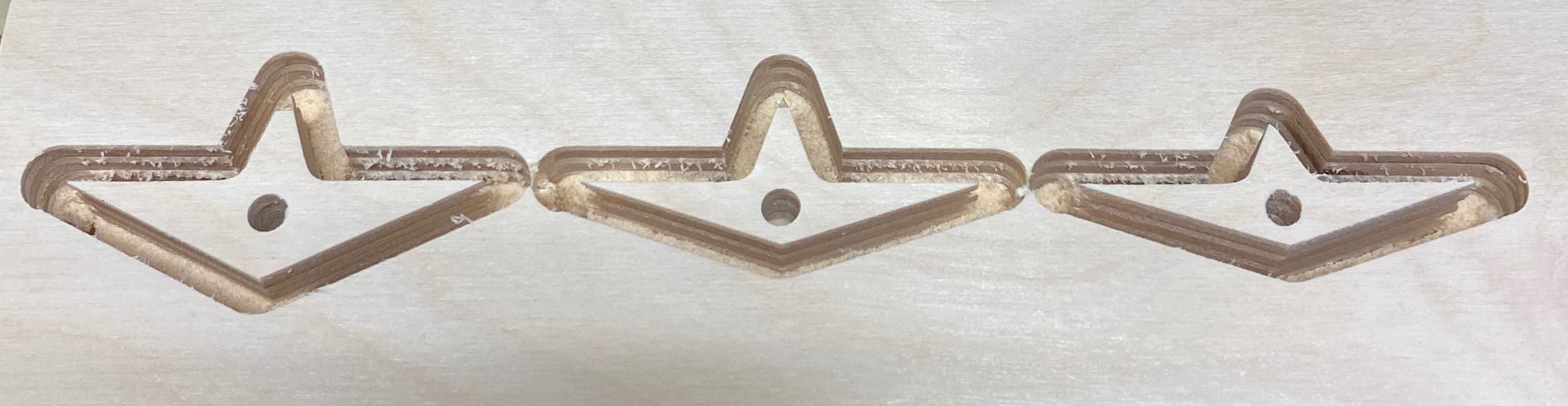
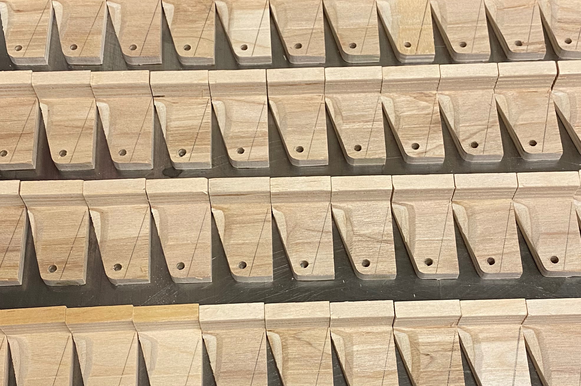
A FEW CONSTRUCTION PHOTOS
Gears:
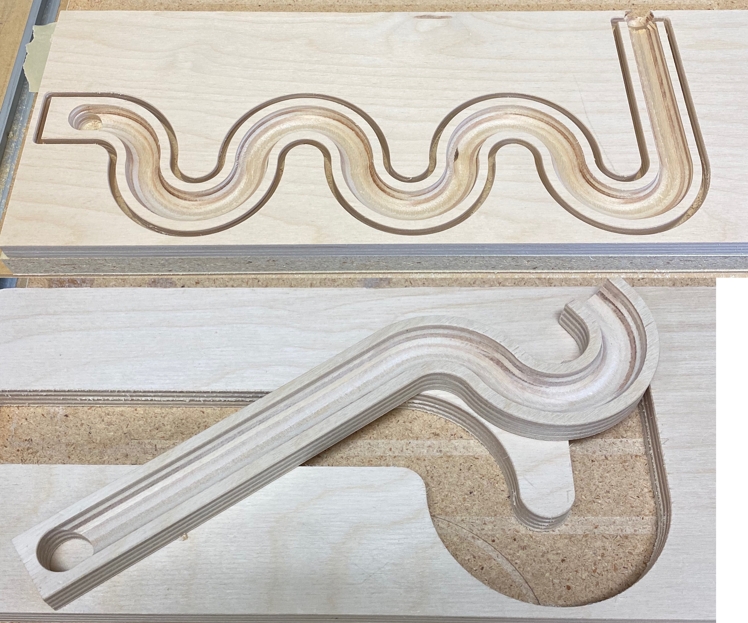
Tracks:
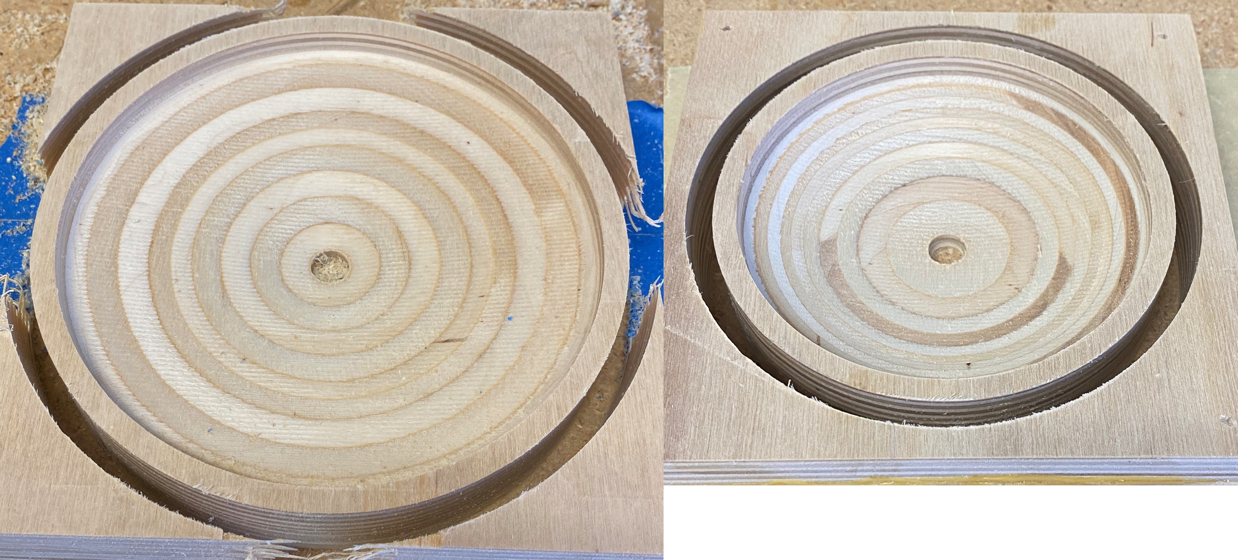
Vortex Bowls:
ZigZag and Gear Bracket:
Left/Right Gates Prototypes:
Spiral Staircase Steps:
Shellacked parts, ready for reassembly:
CARBIDE CREATE DESIGN FILES
Marble Machine c2d files.zip (2.4 MB)
CUTROCKET LINK:
Territorial Cup to you, Sir!

Well I’d better grab a few sheets of ply, this may well be what I needed to keep me busy for the upcoming 4+ weeks of [lockdown, season2]
Okay, when you put the files and plans on line ( for a small fee of course) count me in.
Video, pics and details have been posted!
How am I going to get any work done today, if I keep watching that video in a loop ?!
Great fun, and very nicely made 
@ScottsdaleSteve Awesome! Nicely done. Solid and it sounds great!
@ScottsdaleSteve - Wonderful job with a great mesmerizing effect!!
What bearings did you use for the gears? I was wondering what I was going to do with the Z belt from the maintenance kit, thank for the solution!
Some cheap ones from Amazon: https://www.amazon.com/gp/product/B0824W4SZW/ref=ppx_yo_dt_b_asin_title_o00_s00?ie=UTF8&psc=1
Wanted 1/4" inside diameter so I could use standard 1/4" bolts.