Community challenge #19: CC's Image Tracing (closed)

So before I made a mistake I asked the following

So @WillAdams suggested I ebonize the wood but I read up on the process and it looked like a 7 day affair

However he suggested

Which might seem obvious, but I was so in the weeds of worrying I’d make a mistake and trying to YouTube the perfect solution I didn’t even think to try that

Anyway,

First Step: took some steel wool 0000 to fix the fuzzies. This actually worked extremely well in cleaning up the loose fibres, and didn’t remove the shellac coating.

Step two: flood coated the surface with varathane premium wood stain and used a brush to make sure it went in all the grooves

Step three: After 30 seconds took white tshirt material and wiped it clean. As I had shellac’d the surface prior it penetrated the wood perfectly to accentuate the grain, but keep the yellowness of the wood.

Step four: three coats of oil based polyurethane satin. In my self study on google, the consensus was that the stain on the top will eventually rub off because the shellac had wax in it, but that if you coated it with polyethylene it would seal it.

The results

Super happy with the results and just amazed at what some wood stain would do.

11 Likes

Just in case you missed it, Winston just posted a video walkthrough of the image tracing feature, so now you have fewer excuses to not participate in this challenge :slight_smile:

6 Likes

Well finally got around to finishing the painting on the entry. So the project was for my sister who wanted this awhile ago and luckily the image tracing would be needed anyway so I figured this would be a great project for it.

First I started off sourcing a image since the picture had sent me had to much issues with lighting and angle since she took it at a game. So here is the image I ended up using:

It ended up looking like:

All together the image tracing worked as planned and was much easier to use than the inkscape I had been using. Next I cleaned up the tracing for things I did not need and also straightened the lines. This was done using the node delete and deleting all the nodes between the corners, which straightened everything up nicely. Here was the final product:

Next I created the toolpaths and everything for getting it cut on the XXL. The sign is 28"Wx17"H. Here is the Cut File:
Wrigley Marquee Sign.c2d (1.3 MB)

And final product after painting. The black banner portion is chalkboard paint so she can write whatever in chalk:

Most of the problems on this project were focused on the user. I had painted the 1/2 MDF red and put two coats of water based polycrylic on as I do with most of my projects. This project I used the polycrylic over polyurethane which I normally use. The thickness of the water based product was unexpected and two coats did not do well. After I painted the white I sanded as usual and went through the polycrylic layer into the red causing several places where it went back to bare wood. To get a uniform color right I decided to paint the surface red again, which bled into some of the white so had to go back and touch up the white. Have I said how much I hate painting!

And last the cutrocket link:
Wrigley Field Marquee Sign by hkyswim (cutrocket.com)

12 Likes

I decided to go a little bit more natural and take my first stab at a tray of sorts. I found a leaf from a bush we just pruned and got to it.

FIrst, I scanned the leaf on a basic flat bed scanner. I think I scanned it at 1200 dpi. I got a pretty good file out of it, but since it was so detailed I wasn’t able to get Carbide Create to make much of anything from it. With a little help from photoshop and some curves and exposure I was able to isolate the veins and outline, fill them with black and move into Carbide Create to use image trace.

From there I used image trace, which worked super well to create a vector based image of those two components.

Using model I created the recess in the tray and was able to shrink the veins to fit in the bottom of the tray as well. I did have to trim some of the ends of the veins to fit within that space. End file looked like this.

I had a piece of rustic maple I picked up a little while ago that I didn’t know what to do with, so this seemed like a perfect application. I flattened on both sides on the Shapeoko and went to running this file. Lots of sanding and I came out with this guy.

Pretty new to all of this as I just got my Shapeoko in February, so a lot of these processes were little victories for me. Piecing together a successful pocketing with finishing action, using the live trace, first v-carve. Overall I’m happy with the result.

Things I learned:

  • The finish even after two passes at opposing angles still left a very rough finish. Sanding with hard maple took a while. Maybe more passes next time?
  • Workflow is super important when doing 3d models in CC. You have to set your workpiece depth first, then make the workpiece rectangle, then do the subtraction. I definitely had to go back a few times to correct mistakes.
  • You can actually route the bottom of this funky shape and have it come out pretty good!
  • Not sure how to better finish inside of these little v-carve channels. Sandpaper just made scratches around them so I ended up just leaving the little fuzzies on the inside, which I don’t think you can see in the end.

Cut Rocket
C2d file: Leaf Tray.c2d (2.3 MB)

19 Likes

The usual suggestion to clean up V carve fuzzies is to just re-run the V carve — possibly after spraying a fixative.

My inclination would be to just use a parting tool which had the same (or slightly more acute) angle than was used for the V carving:

2 Likes

Toothbrush is usually how I clean up some of the fuzzy stuff

3 Likes

I’ve experienced this same issue previously. Decreasing the stepover takes longer to cut, but decreases the sanding and I really do not like sanding.

Beautiful job on your entry!

2 Likes

I have been a Doctor Who fan since the 1970s, and was delighted in the early 2000s when BBC restarted the series. (For those who are unfamiliar Doctor Who follows the exploits of a Time and Space travelling Time Lord from the planet Gallifrey with multiple lives known as “The Doctor” who finds him/herself in situations resolved through wit and intellect.)

After the new series was started in the mid 2000s the series took a series of excursions into darker moral territory, one of which detailing when The Doctor had spent one of his/her lives fighting in a terrible war across time and time. During the episode (The Day of the Doctor) it is revealed that his nom de plume “The Doctor” is a Promise: “Never Cruel nor Cowardly. Never Give up, Never Give in”

As a military officer and father I’ve found this bit of fictional lore a steadfast guidestar, and wanted to commemorate it in a way that had a deep meaning to me (and didn’t violate copyright.)

I started with the fan-fiction version of the Gallifreyan language developed by Loren Sherman, specifically the Adrian17 version of the language generator on Github. I found this interesting, but it didn’t have that personal feel (and it didn’t fit on the piece of Red Oak I wanted to use.)

So… I had to learn to write in Gallifreyan.

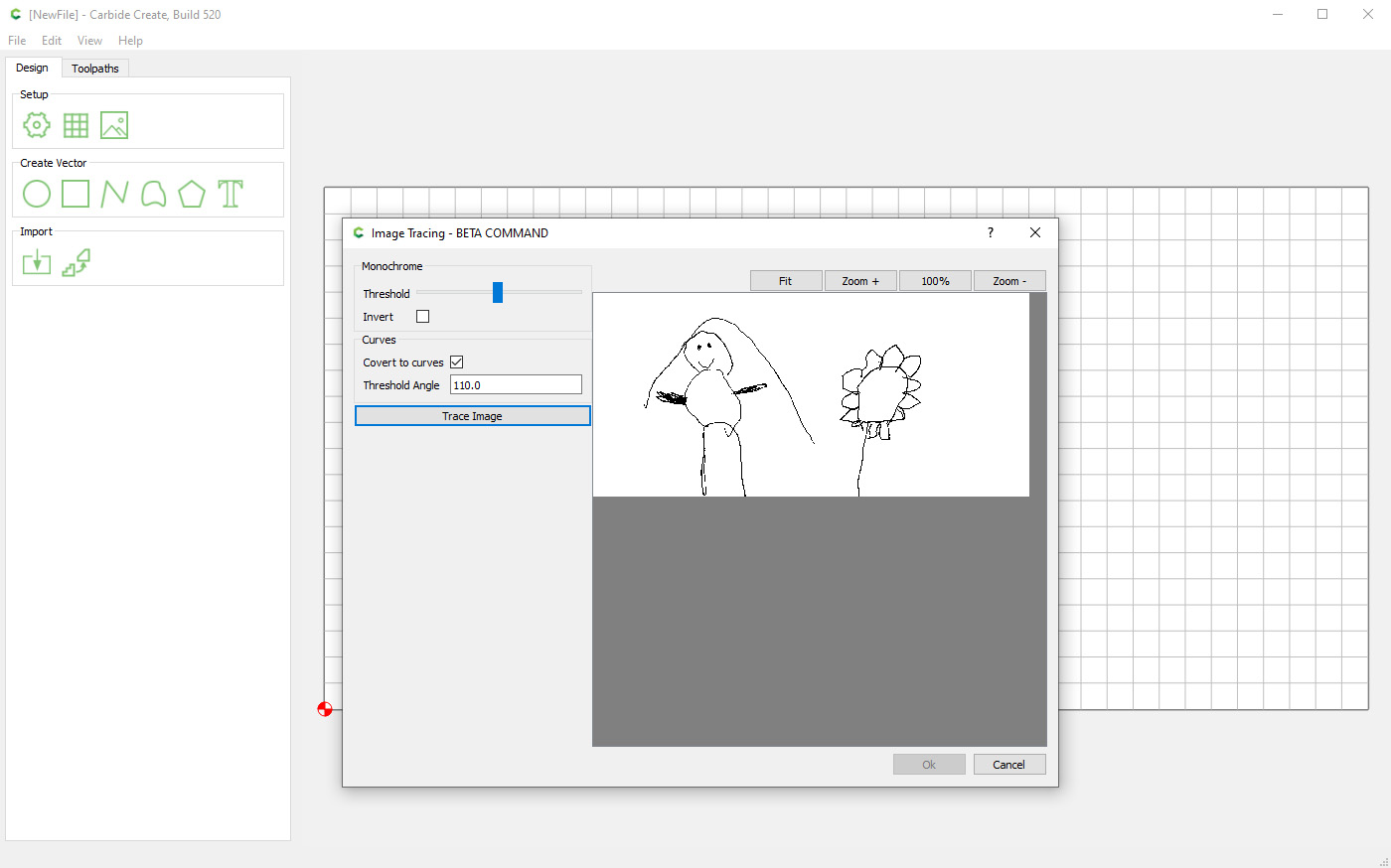
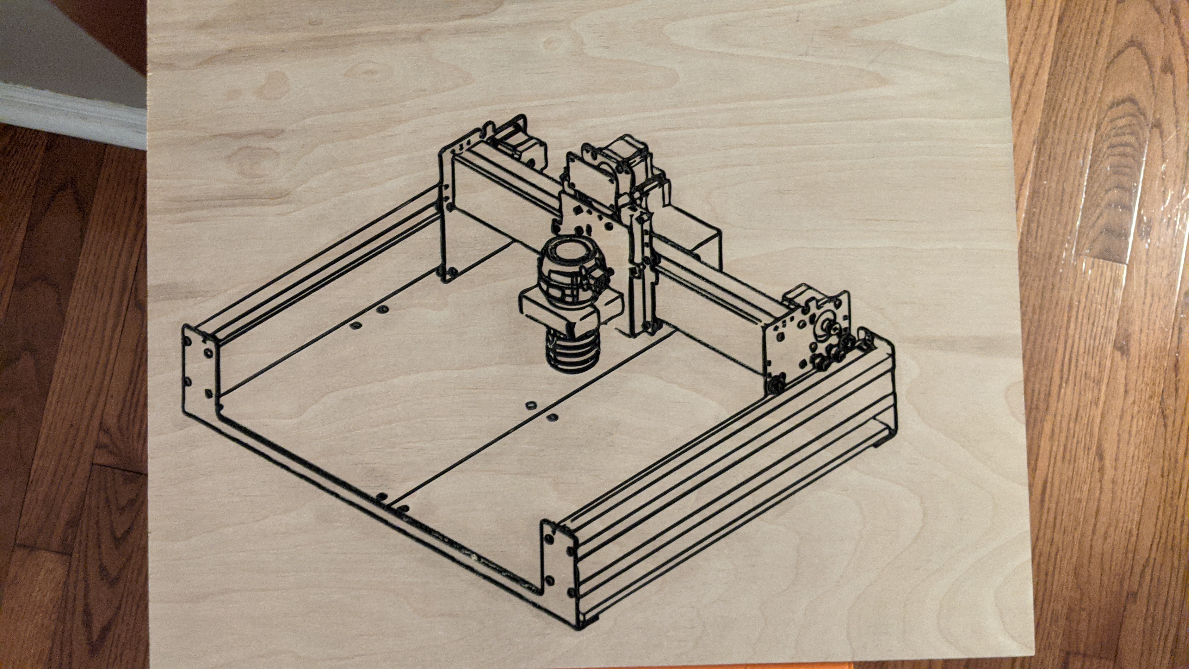
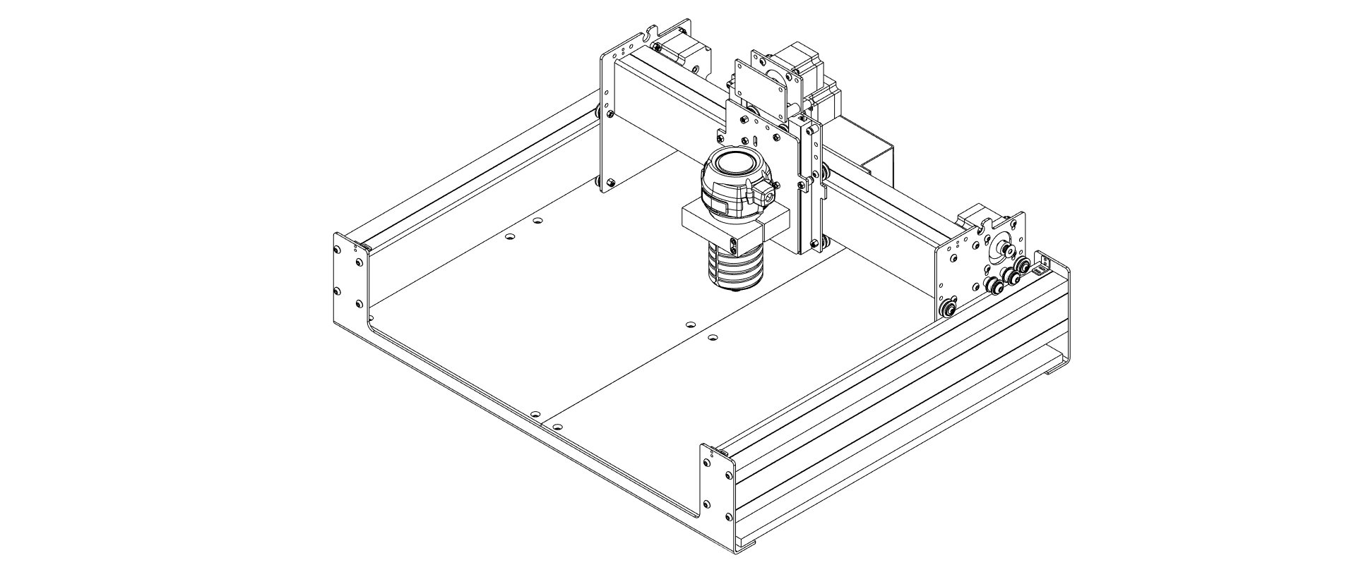
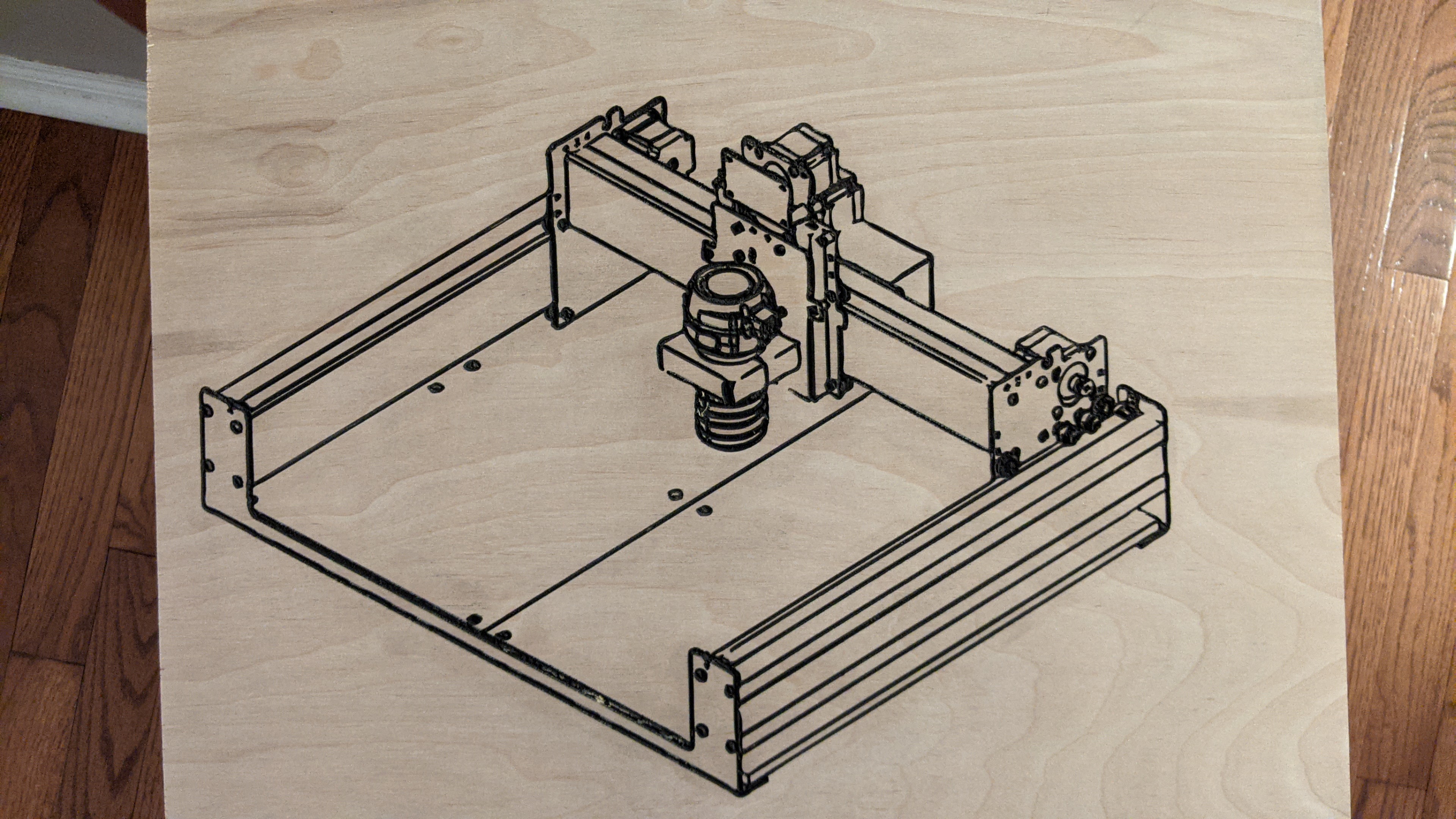
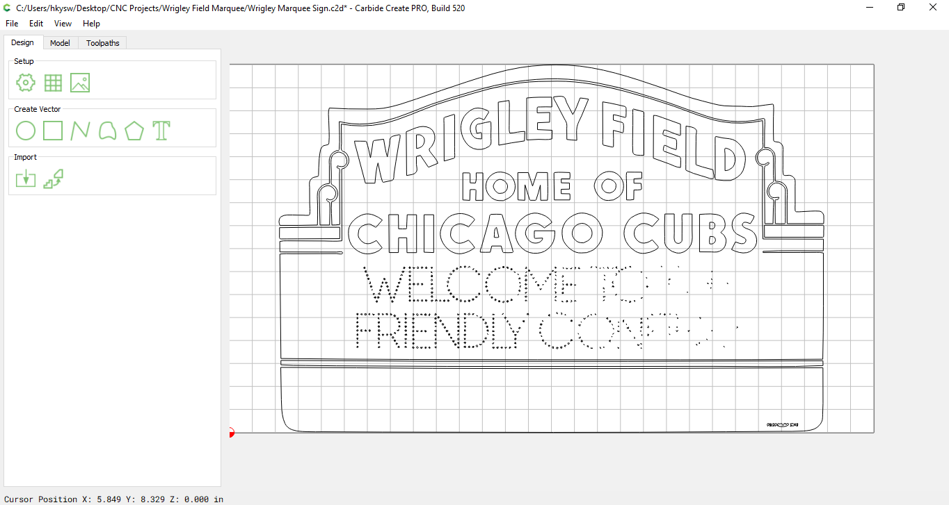
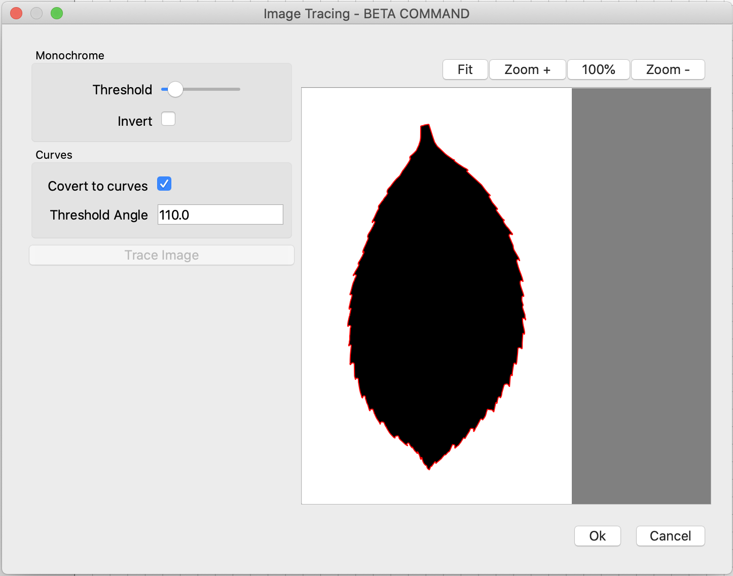
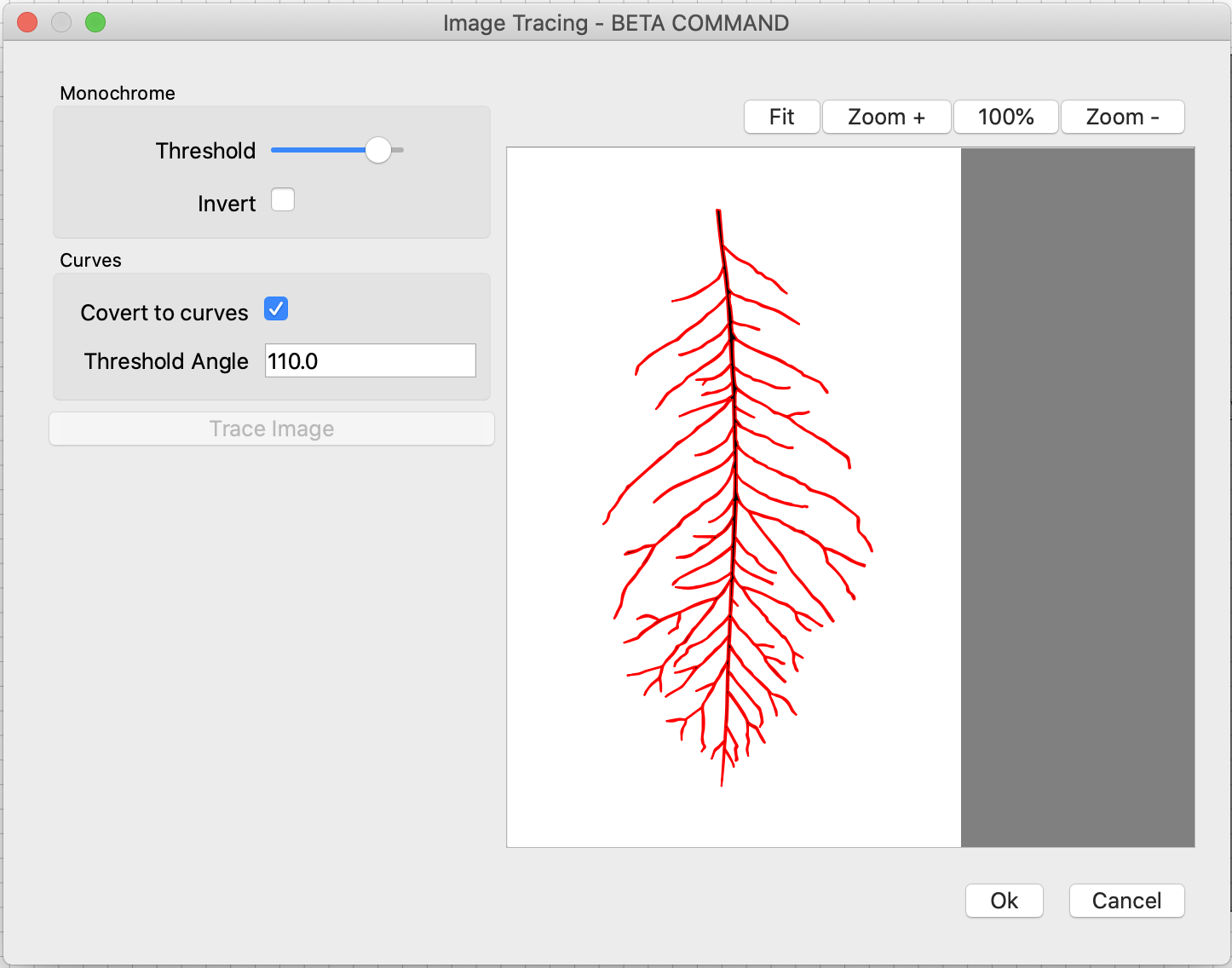
The words are written in a circular fashion, with some words having divots that can be artistically arranged with leading/following words to make a beautiful pattern. Line extensions for some letters can also be artfully woven into the overall pattern of the phrase leading to a unique design. I figured out the words, did some practice drawing, then brought it together into a final version which I scanned and imported via the new Carbide Create tracing tool.


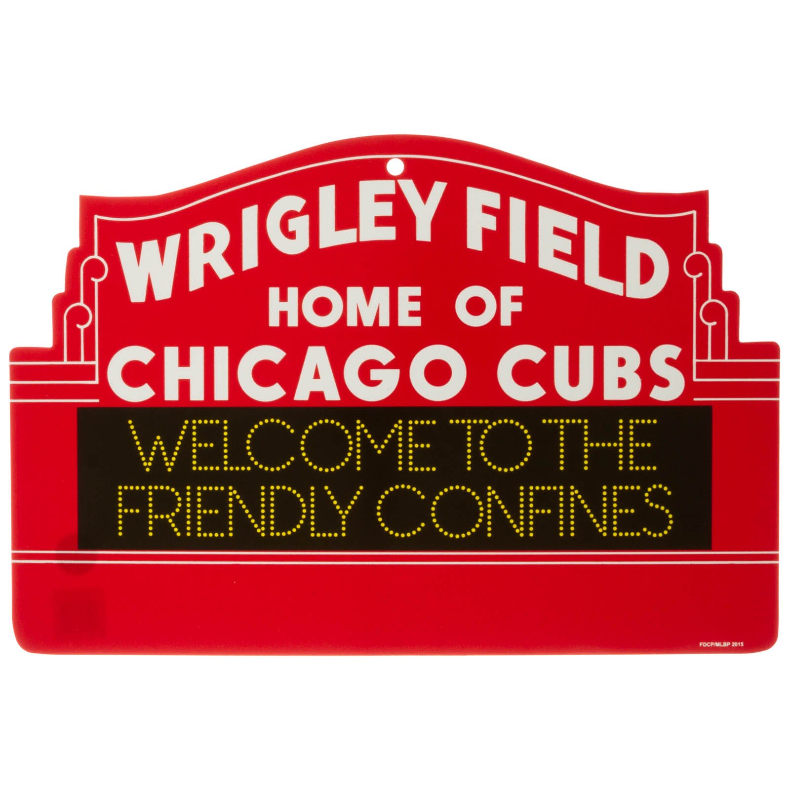
After importing using the Trace tool I chose to put the English translation above & below the graphic, and did several hours of cleanup on the traced image. (More on that at the end.) I ended up replacing a few of the small circles that didn’t come through the scanning process well with Carbide Create graphics.

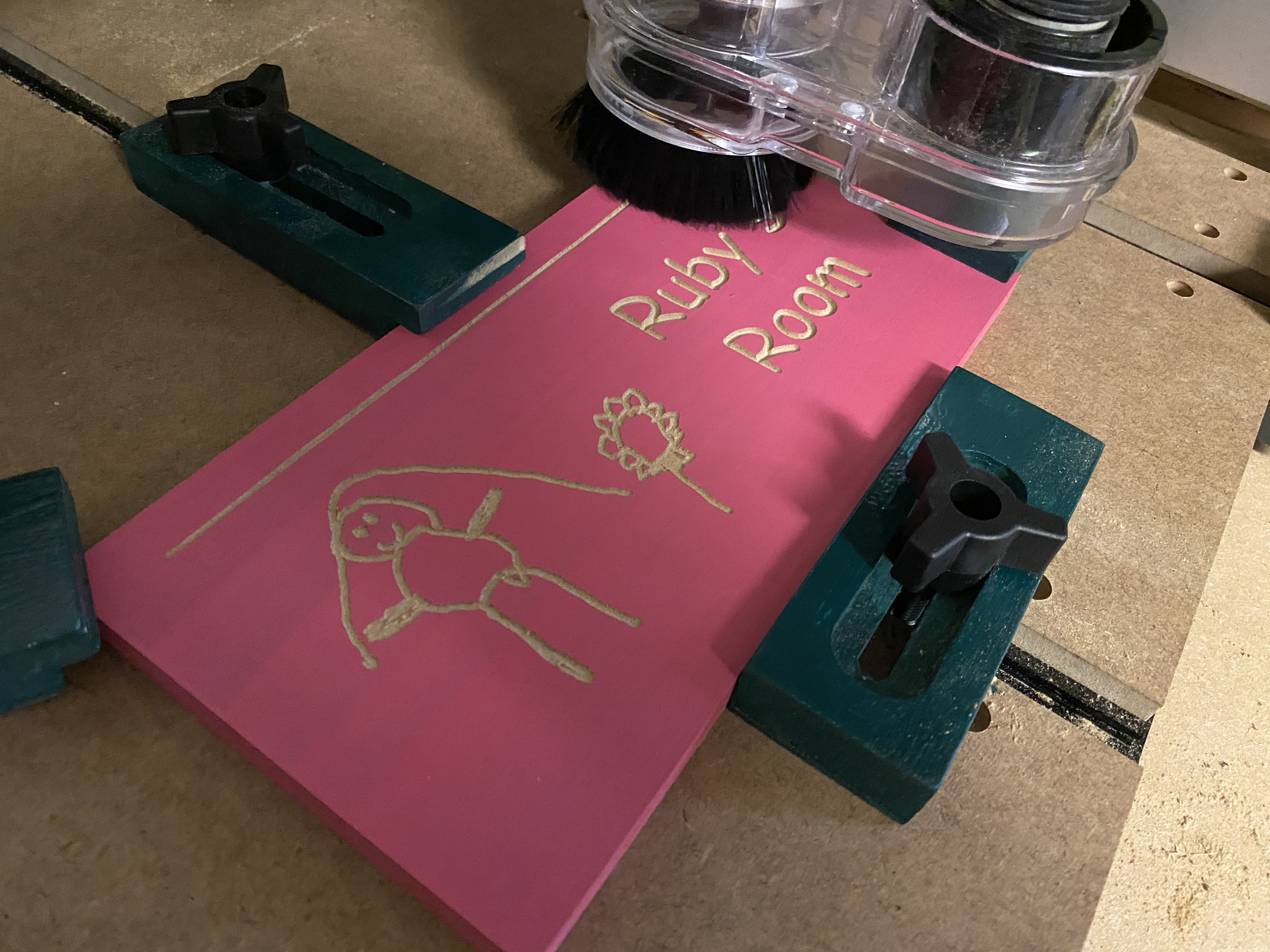
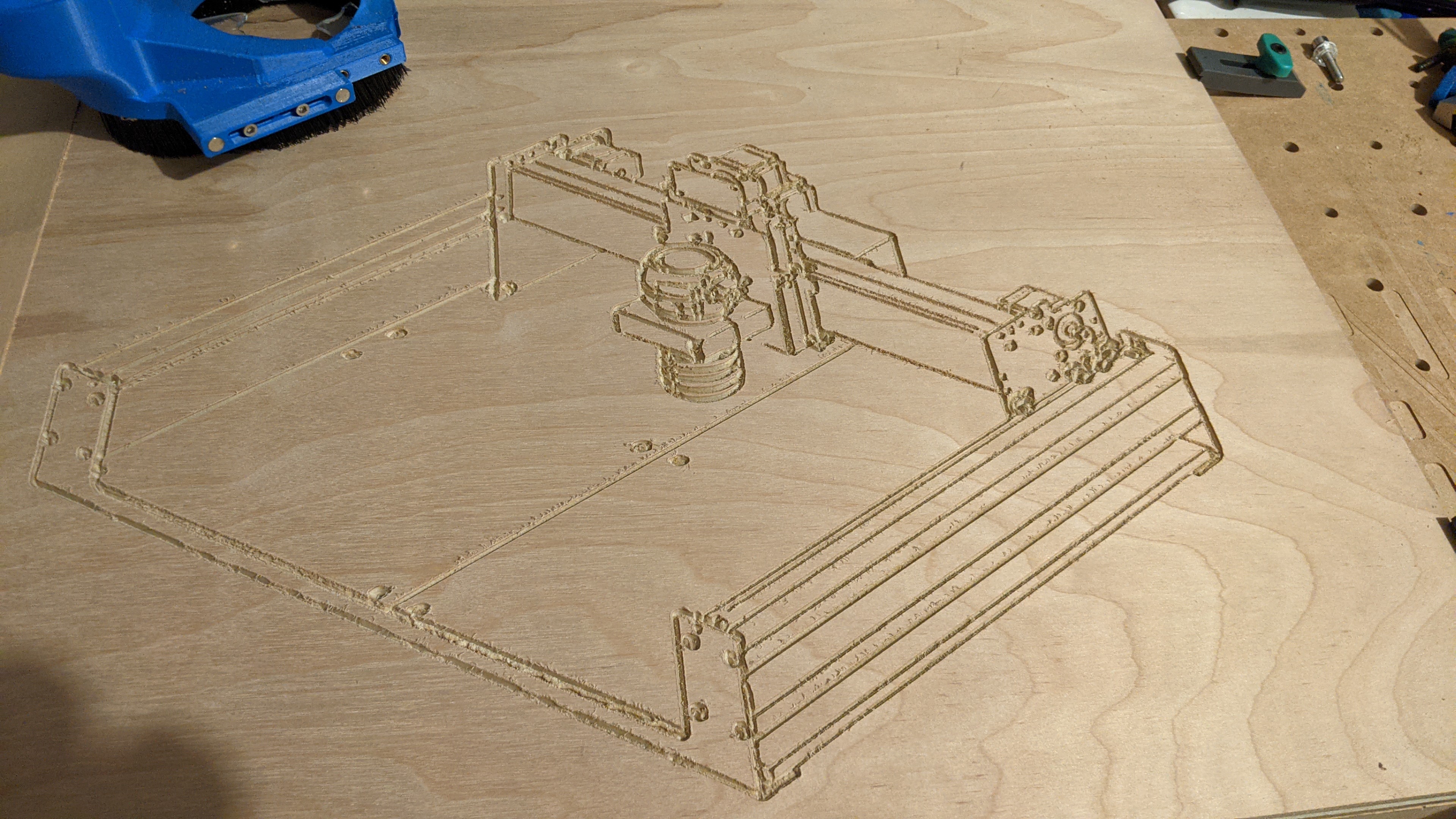
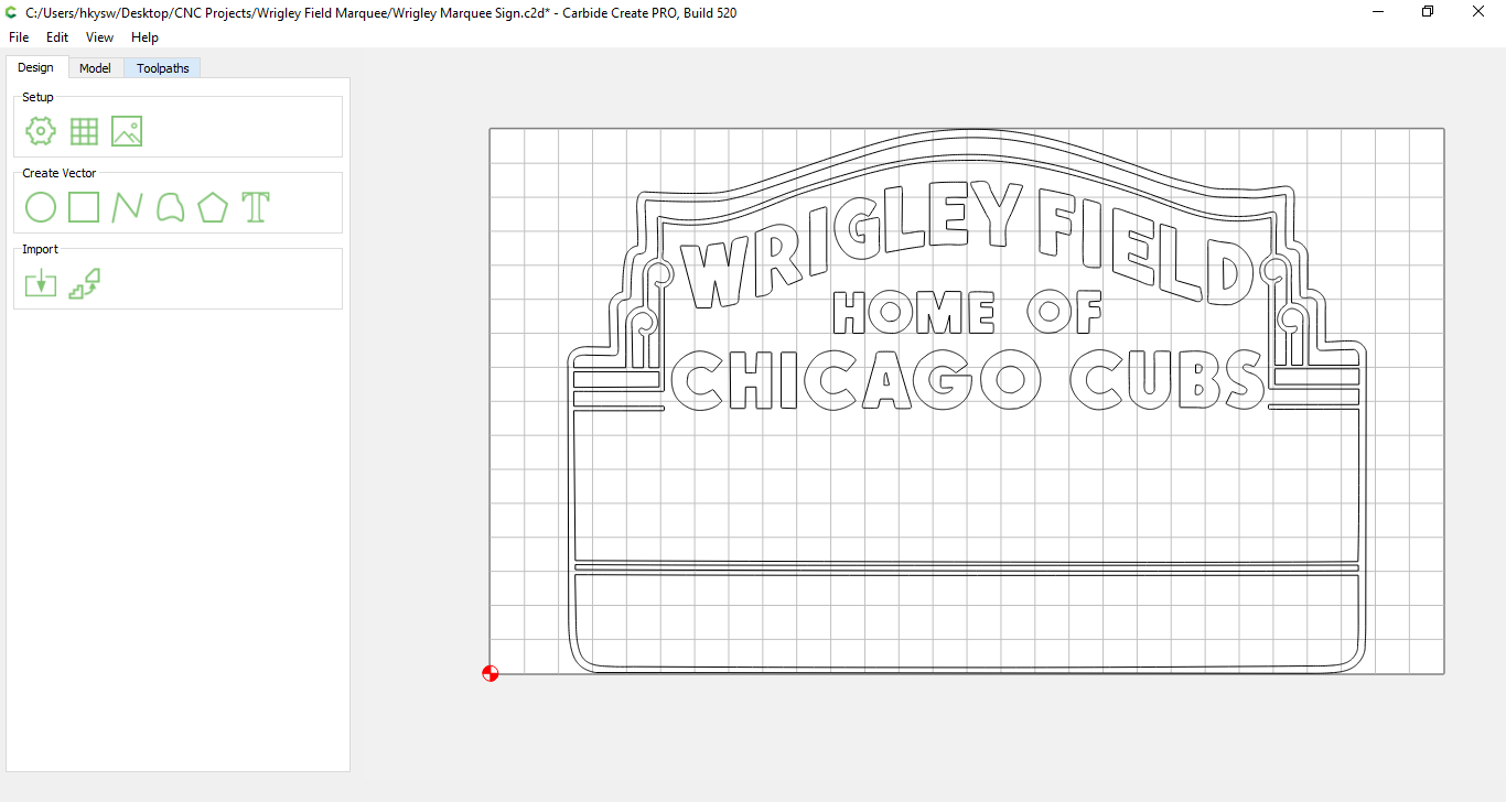
Once I finalized the design I carved it with a 1/8” Endmill for the relief portions and a 60 degree V-Bit. This left me with a 2mm deep pocket to fill with the Doctor’s signature color: Blue. (It’s a TARDIS thing.)

After cleaning up the cut with some sandpaper and diamond files I sealed the wood with water-based polyurethane and poured about 4 ounces of Azure Blue colored epoxy into the recesses and allowed it to harden overnight. I deliberately overfilled the form to allow me to sand it down to an acceptable contrast. In hindsight I added waaayyy too much epoxy. Chalk it up to a rookie mistake, all it cost me was time and shoulder pain.

Then the sanding… About 2 hours of sanding with 80 grit to get down through the epoxy to the carved pattern, then a progression up to 3000 grit. This was my first time working with epoxy or any sandpaper grit above 320, definitely a bit of a learning curve.

Finishing was with Watco Danish Oil. I may put a coat of poly over it in the future. Overall I’m ecstatic with how it came out, and am looking forward to adding epoxy into future projects!

Things to improve in the Trace feature:

  • We need a selectable despeckle option, with a variable for items smaller than ‘X’ pixels to ignore. I spent hours removing 2-3 pixel specks in the design.
  • A cutoff slider would be nice, allowing us to set a darkness threshold below which to ignore.
  • A smoothness feature would also be nice. We already have the ‘Convert to Curves’ and threshold value, but it seems there should be a way to fair a line through a feature more smoothly. I also spent many hours deleting an abundance of nodes that could have been replaced with a well formed curve.
  • Live Preview, and a smoother running Threshold slider. The slider is very jerky, and it makes it hard to get exactly the right spot.

Trace is a great addition to the Carbide Create toolbag, I look forward to using it on future projects!

If anyone is interested in making their own version the CC file is on Cutrocket or you can download it below. All images & files are covered under Creative Commons-Attribution-NonCommercial-ShareAlike

Doctor Who - The Promise.c2d (1.2 MB)
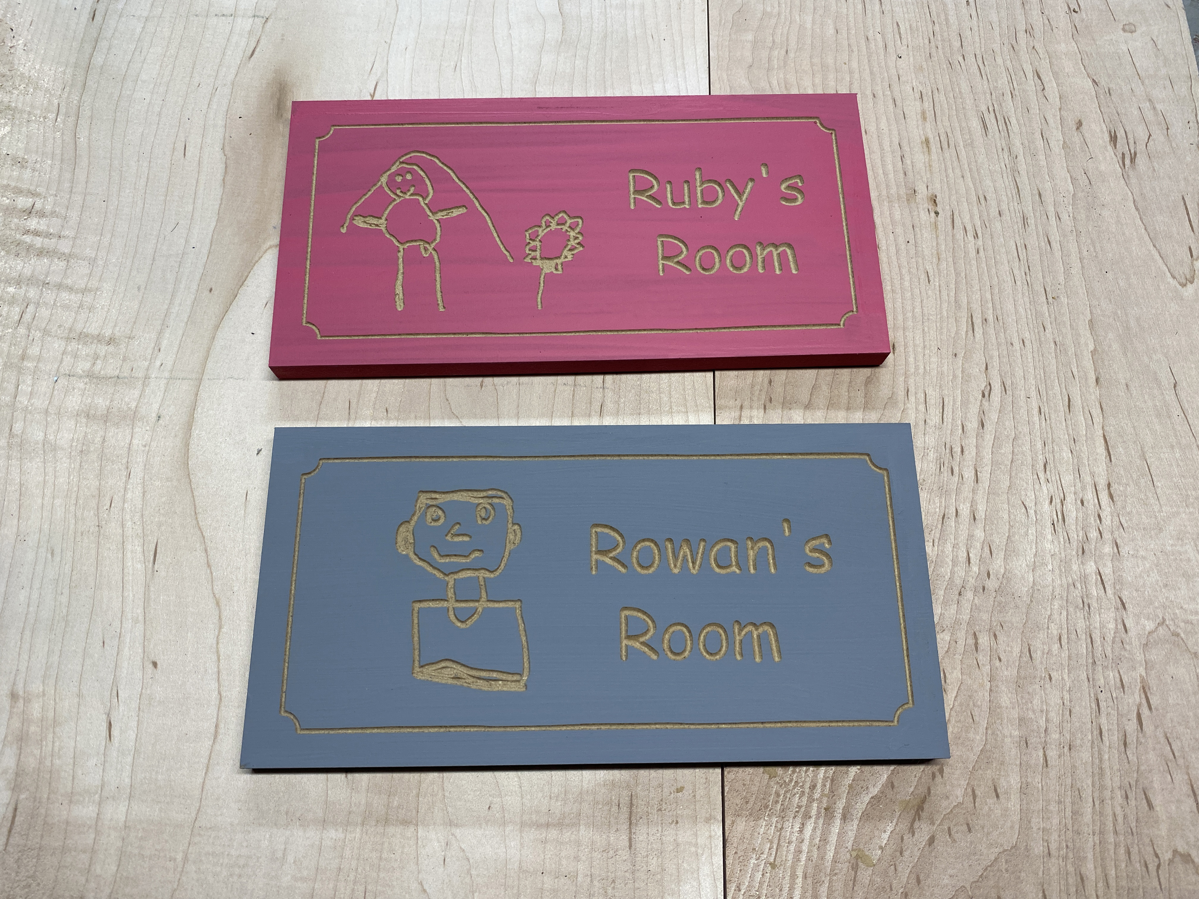
12 Likes

I did this exactly once, and swore to never, ever do it again, so now I just leave the piece on the wasteboard, pour epoxy there, call it a night (or day, or two), then…use the Shapeoko to shave off the extra epoxy down to the desired level, with a multi-pass surfacing operation. Your shoulder will thank you

Thanks for the pretty cool entry !

6 Likes

Nice fusion of vcarve and resin inlay. I had good success for sanding using a spindle mounted, foam cushioned with Velcro mount for 2” sanding discs. Zero like normal (paper slip method) the set a ‘cut depth’ of about 1mm which compresses the foam and ensures good contact. Choose an appropriate tool path to steer the sanding and run-re-run it with successively finer grades. I then used a buffing pad with a polishing super-fine grit using the same setup

3 Likes

I concur.

2 Likes

This project started with a free SVG file from Suncatcherstudio.com of a simple jigsaw puzzle before the addition of Bit Mapping to Carbide Create,

The puzzle consists of four parts

Frame - 3/4” MDF with a pocket for the remaining parts
Base – 1/4” Baltic Birch plywood with outline of puzzle and parts drawn with a Sharpie in a plotter fixture for the Shapeoko
Inlay – 1/4” Baltic Birch plywood with an opening sized to accept the parts
Parts – 1/4” Baltic Birch plywood

I used the SVG file format which resulted in an immediately usable outline of the puzzle and its parts. These were drawn with the Sharpie using a plotter fixture on the Shapeoko. The pattern was drawn using a contour tool path with no offset.

In addition the resulting pattern from the SVG file let me delete the vectors defining the parts leaving only the outline. This outline was used to create the opening in the inlay for the puzzle parts using a contour tool path on the inside of the line.

I converted the SVG to a bit map file and used the trace function in Carbide Create. It separated out each piece of the puzzle which allowed the parts to be cut out using a contour tool path on the outside of the line.

One of the other issues I had to contend with was using the Sharpie. The ink bled into the Baltic Birch plywood and also reacts with finishes that contain solvents. The solution was to apply two thin coats of shellac to the base before drawing the outline of the puzzle. Then a top coat of MinWax water based polycrylic over the acrylic paint and Sharpie drawing.

The pieces were cut to size on a tablesaw and a roundover bit in a router table was used to soften the edges of the frame. All other milling was done on the Shapeoko.

The lesson was even for a simple project like this it took a mixture of tools to get the desired result. Vectors from the bit map tracing tool, vectors from the SVG file, a plotter fixture for the Shapeoko and a tablesaw to efficiently cut the various pieces to a uniform dimension.

Car Parts Outline 1.3x.c2d (112.8 KB)

Car Inlay 2.3x.c2d (26.9 KB)

Car Parts 2.3x.c2d (184.6 KB)

9 Likes

This isn’t very sophisticated, but I wanted to get my kids more interested my new CNC hobby. I made a couple of signs for their rooms using the new trace tool in Carbide Create to vector-ize their self portraits. First, I had my kids draw their own image.

Second, I photographed those images with my phone and brought them into Photoshop to convert them to black and white images that Carbide Create could better trace. With the trace tool in Carbide Create, I converted the raster images into vector:

Then, I painted a couple of pieces of 1/2" MDF for the signs and put them on the Shapeoko 3.

Ruby helped by supervising some of the work. So far her favorite thing about the Shapeoko 3 is using the NES controller to jog the machine.

And here’s the finished project. And yes, that’s an appropriate use of Comic Sans!

I also uploaded the files to CutRocket in case anyone wanted to see the nuts and bolts, but I can’t imagine that anyone would want to make these particular signs. https://cutrocket.com/p/6061215c56f87/

16 Likes

Here’s my last minute entry to the challenge.
I fooled myself into thinking I’d have time. Yesterday was sunny and 70°F. Today…weird sleet. I’ll still need to trim the stock and apply a finish, but this will hang in my garage.

I started with an old Fusion model of the original Shapeoko 3 and added a model of the Dewalt router. From there, I changed to a wireframe view and snagged a screenshot.

The rest was too easy. In Create, set my stock to 17.5" x 13.5", used the image trace tool on my screenshot, fixed one spot I didn’t like but left the rest “natural”.
Used a 60° CMT tool. Took about 15-20min to carve.
My 4yr old helped me paint with black Crayola project paint.


Got back to it several hours later and sanded off the slopped on paint.
I like how it looks like a rough sketch like you’d imagine @edwardrford might’ve drawn on a napkin.
It was also a quick project and I liked the ease of using Crayola paints.
My decision to purchase an SO3 in 2015 changed my life (I can’t park in the garage anymore), and I thought it deserved a place on my wall (the walls inside the house are my wife’s and kids’).

CC file: CC_ImageTrace.c2d (862.4 KB)
Gcode: imageTrace_CC.nc (282.5 KB)

Edit: Stain went a little darker than I envisioned, but…


Maybe I should throw it in a maple or cherry frame? What do you guys think?

10 Likes

Not quite original, since the homing switch plate was a later addition (and it’s missing the top two spacers for the plate).

It still speaks well to what great looking designs all of the Shapeokos have been — the SO1 was almost unbearably cute (save for the belt anchors)

and the SO2 was just great looking:

and the SO3 while not taking the greatest photos due to the proportions (XL and XXL are better in that regard) has a hefty, no-nonsense appearance in person.

5 Likes

Thank you all for participating, this way for voting please !

3 Likes

Very nice @mhotchin! What bit(s) did you use for this?

That’s right. I nearly forgot about the exciting limit switch add-on kit.
I’m probably missing two spacers because I took them to the hardware store… I couldn’t believe that they didn’t fit any of my vast assortment of metric hardware.

2 Likes

Yes, the spacers being Imperial (#10-24 or was it 1/4-20?) was an odd decision — fortunately, we’re all in on metric now, save for the option of using 1/4-20 for workholding where appropriate. That said, the switch plate was obviously designed in from the beginning and the machine looks unfinished w/o it.

Also, the electronics enclosure is rendered as a box which looks more like the later sheet metal enclosure than the original bent alu. (the appearance of which I never much liked) and the plain unadorned box always appealed to me.

2 Likes

@Hammy89 Just a standard 60 degree V bit!

1 Like