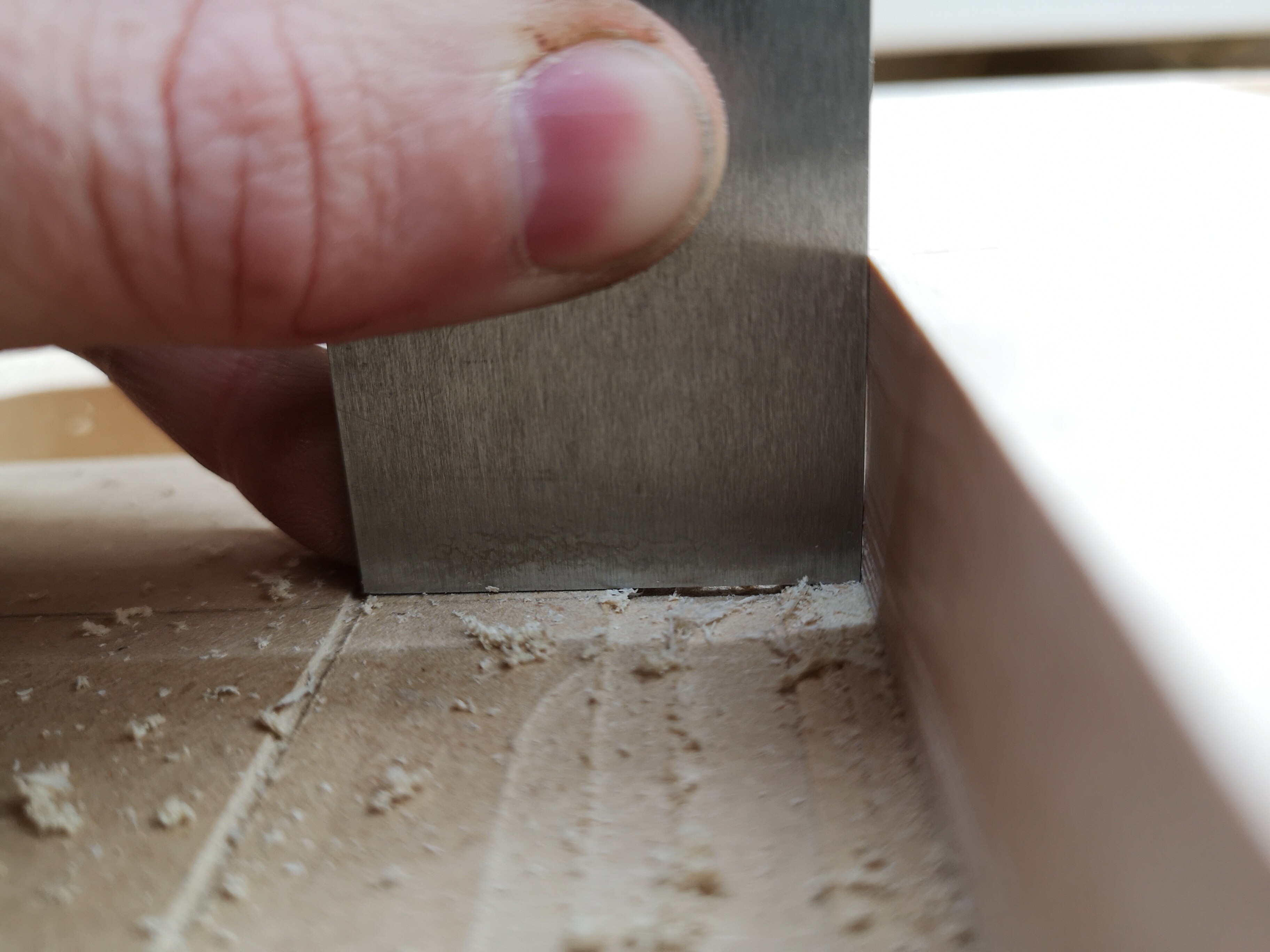
On my shapeoko 3 XXL, I was doing some testing on contours to take out the machining marks left from cutting out contours with multiple depths and ended up with the side actually being scalloped.
I cut the contour with 1mm depth of cut at about 60 inch/min with the carbide spindle. I then took 10 passes at full depth at the same speed, only taking off 0.1 mm per pass until I took off an additional 1mm.
This left the contour being scalloped (concave) rather than flat 90° to the top. Is this simply because of bit deflection?
Sorry, I don’t see any scallops, mussels, clams or lobsters. Could you have perhaps meant concave? I’m a little confused. Perhaps holding a straight edge to the surface that you are describing might help us understand.
Is it a slotting toolpath? Is adding geometry so as to cut as a pocket and leaving a roughing clearance and then taking a full-depth finishing pass an option? Where possible avoid slotting and add geometry and cut as a pocket (Making vacuum hose adapters and/or Adding geometry to cut as a pocket with a finishing pass ) and consider leaving a roughing clearance and taking a finishing pass.
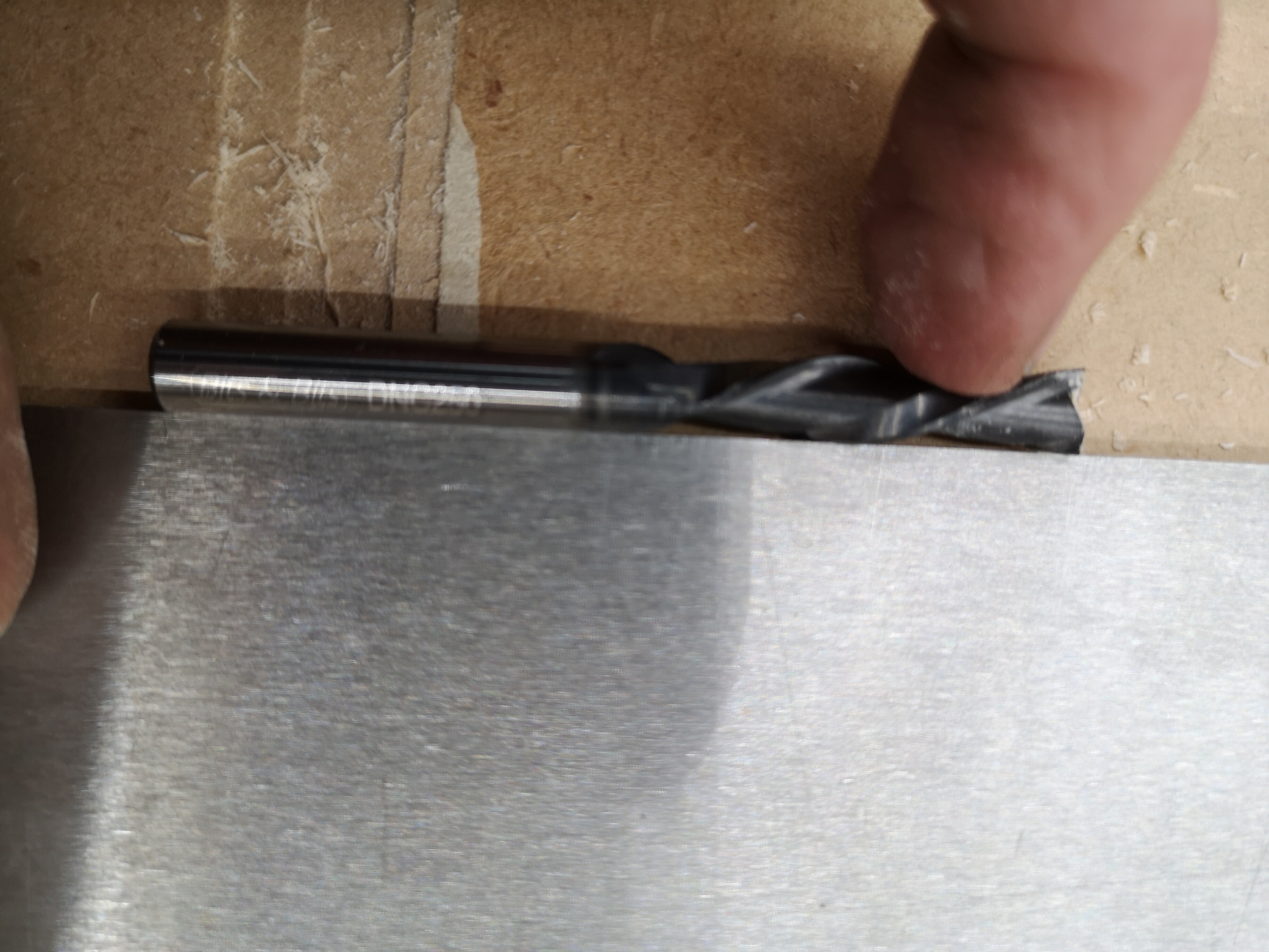
It’s a downcut 0.25 flat windmill with 1"LOC at 18k rpm in the carbide spindle.
I predominantly use fusion, so it was a 2D contour operation but it was an open contour (one straight edge). This I assume would be essentially like a slotting toolpath because it was cutting in a straight line, coming back to where it started the cut and then cutting in a straight line again with each step down. I wouldn’t normally use an operation like this, other than I wanted to just test on one edge and not waste wood. Do you think it’s the way that the bit approaches the wood in the toolpath that causes the deflection? Is that why you wouldn’t use slotting? Or is it something else
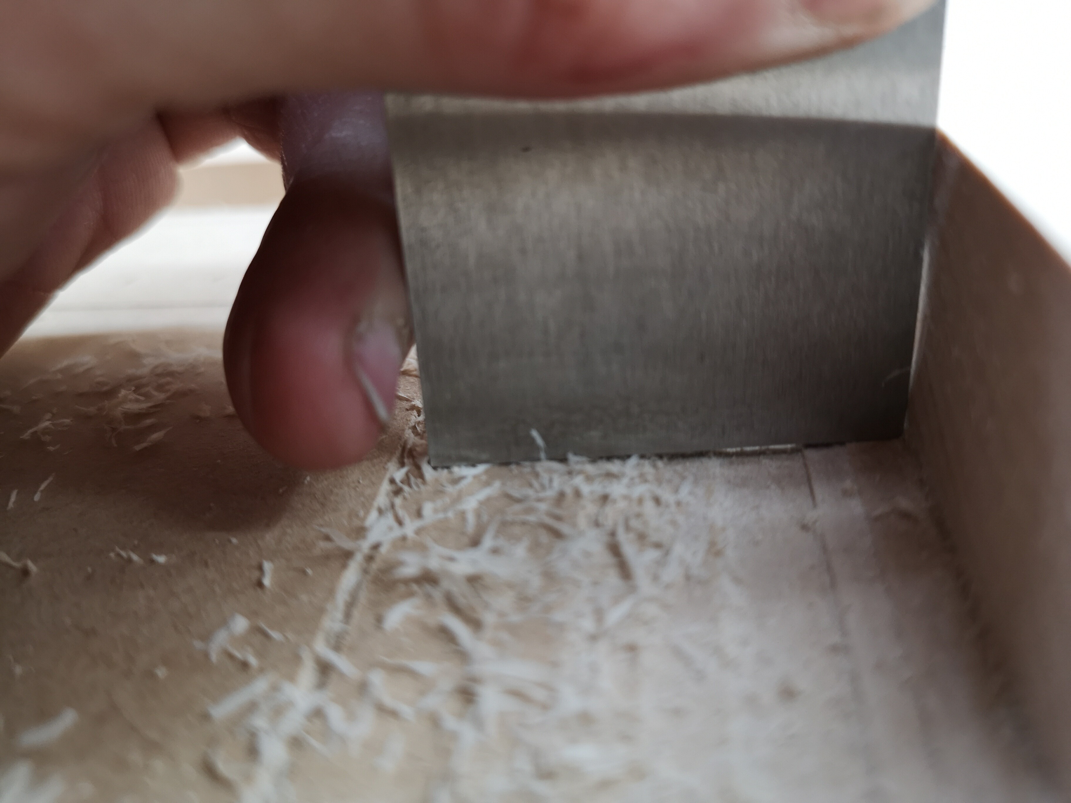
I’d let the initial slotting run then pause the job and measure the cut you have, whether it’s vertical, if not how it is distorted, what the depth of the concavity is etc.
There are various forms of deflection which are possible in the machine during this cutting which can cause the cutter to move around and create this sort of profile. I’ve not seen this sort of shape before but I can see how it might happen.
I’d then run full depth finishing passes and see how those affect the finish. They should eventually take out the concavity and ideally bring the cut to vertical. As stated before, the cutter should produce a straight vertical cut (did you check the cutter is OK?). If not, that will be instructive in itself.
So I ran another test, I did everything the same except I went slower (40 inch/min) and I did 20 0.1mm finishing passes for a total of 2mm. This is what it looked like before the full depth finishing passes
I don’t understand why but actually appears to be more concave after the finishing passes. And there doesn’t seem to be anything wrong with or unusual about the bit.
Checking the cutting profile of a helical cutter can be tricky though, it might be worth using it in a regular router on similar depth (using a fence) and see if you get the same shape out of it?
Alternatively do you have an alternative bit of the same length and diameter to try in order to isolate the bit or the machine?
I did the exact same thing with 3/4" material and the standard 0.25 downcut endmill (0.75 LOC) from the carbide 3D store and got a similar result, although possibly less concave.
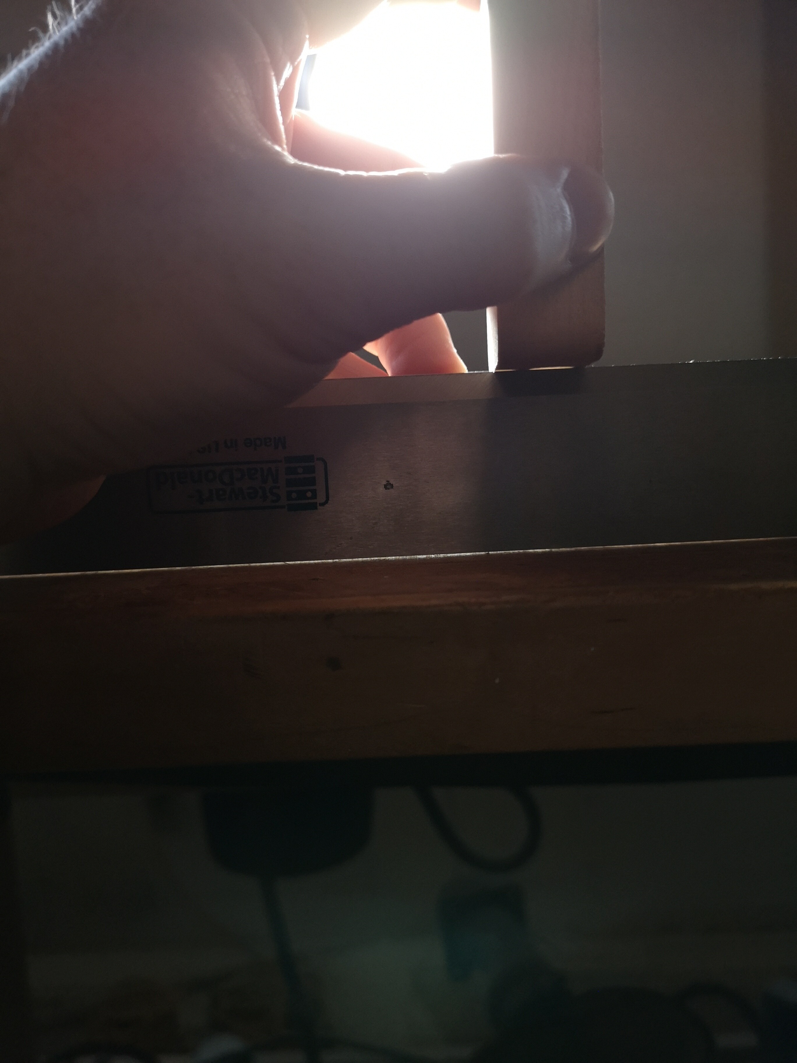
Could this possibly be slop in the collet? This is the original collet on the carbide 3D spindle I bought about 2018. I can’t upload a video but when the bit is tight in the collet I can move the collet back and forth enough that I can’t really see it move but it makes a sound. Is it possible the precision collet on the website would make a difference?
Until now that I’m trying to do inlays I assumed it was cutting square to the top, maybe it never was.
Is that the whole router spindle moving if the nut & collet rock back and forth? If so that sounds like spindle bearings wearing out which won’t help at all.
Try without the collet, bit or nut and see if you get the same slop?
I don’t understand how that would allow a straight bit with full depth engagement to cut a vertical curve but it won’t be helping.
The stock collets bundled with the routers are only okay — best bang for the buck upgrade these days is to replace them with a set of precision collets, either ours: