I need help on connecting 3 or more open vectors. I have a pair of dice that I am trying to create but cant close some of the vectors
1 Like
If you can post the file, we can take a look.
If you can’t close some of the vectors, are they all magenta when not selected?
All the vectors in the selection must be open (magenta colored) in order to join them.
No they are not all magenta. It’s a pair of dice each with 3 sides

Dont know if you can see the pic. Trying to figure out how to send the file
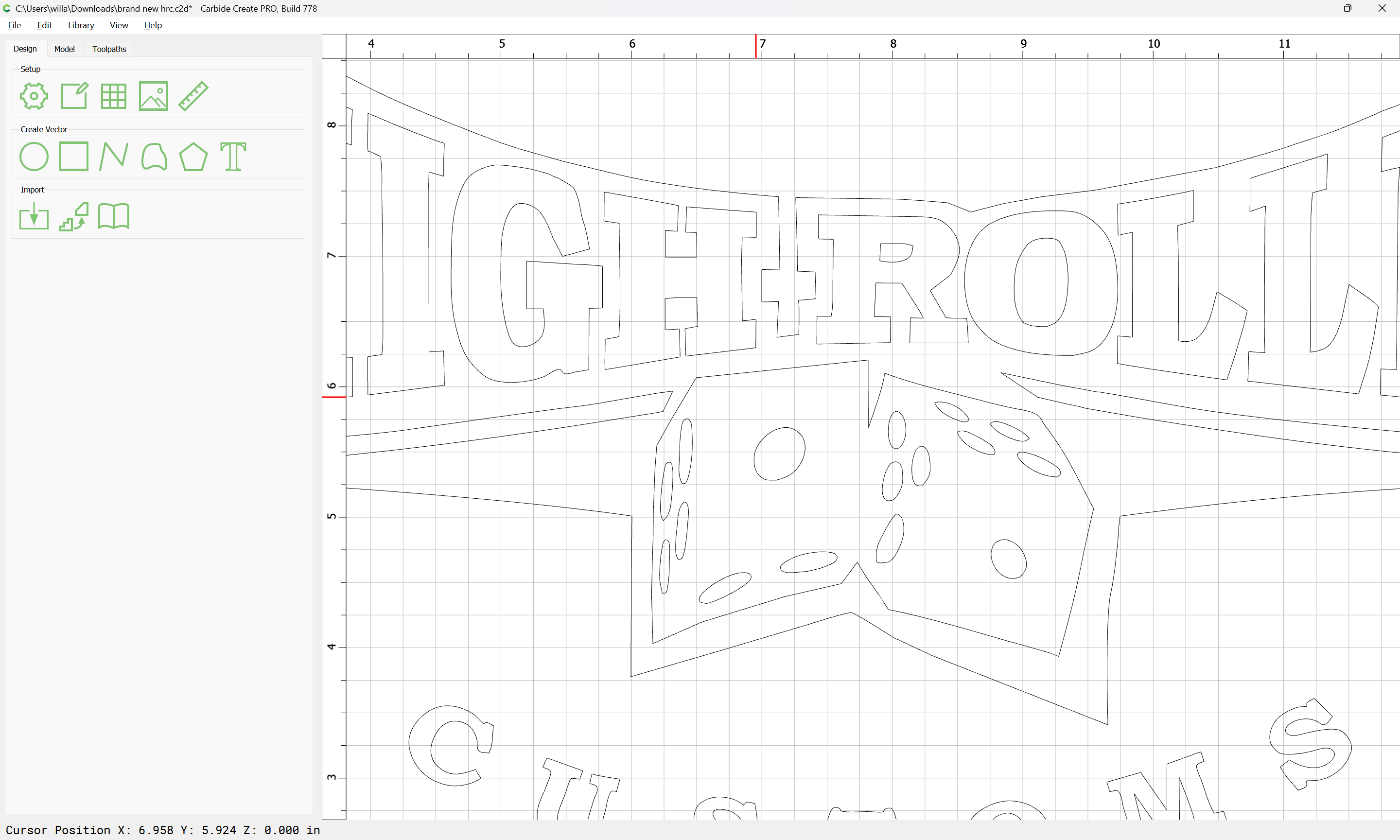
To upload a file, use the “Upload” icon:

If the geometry is not magenta and does not describe a closed region intrinsically, it will need to be edited so as to be open and describe a closed region, then it can be joined.

You need to edit the geometry so as to create a set of curves which describe the region which you want the closed geometry to enclose.
Upload the file and will walk through this with you.
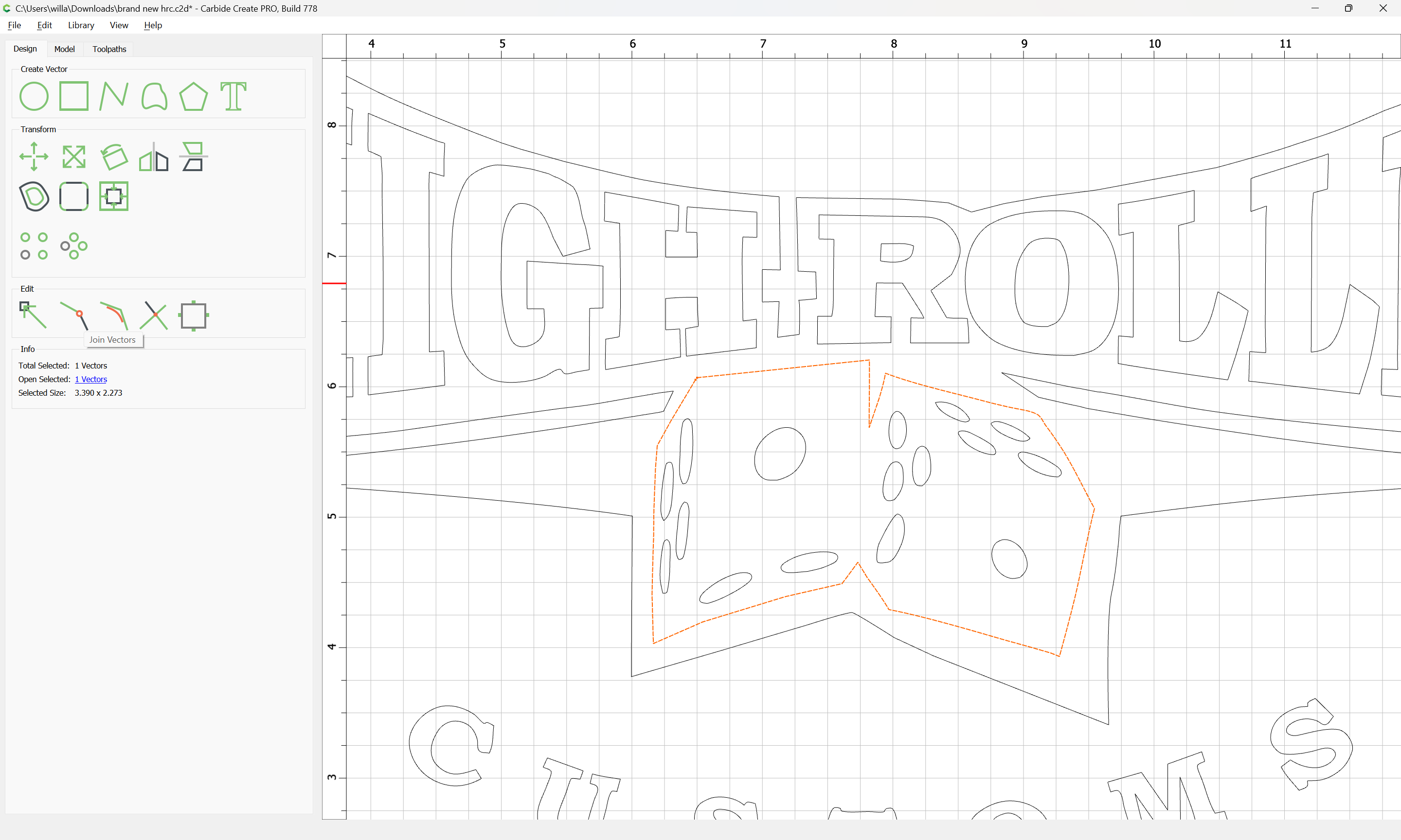
brand new hrc.c2d (212 KB)
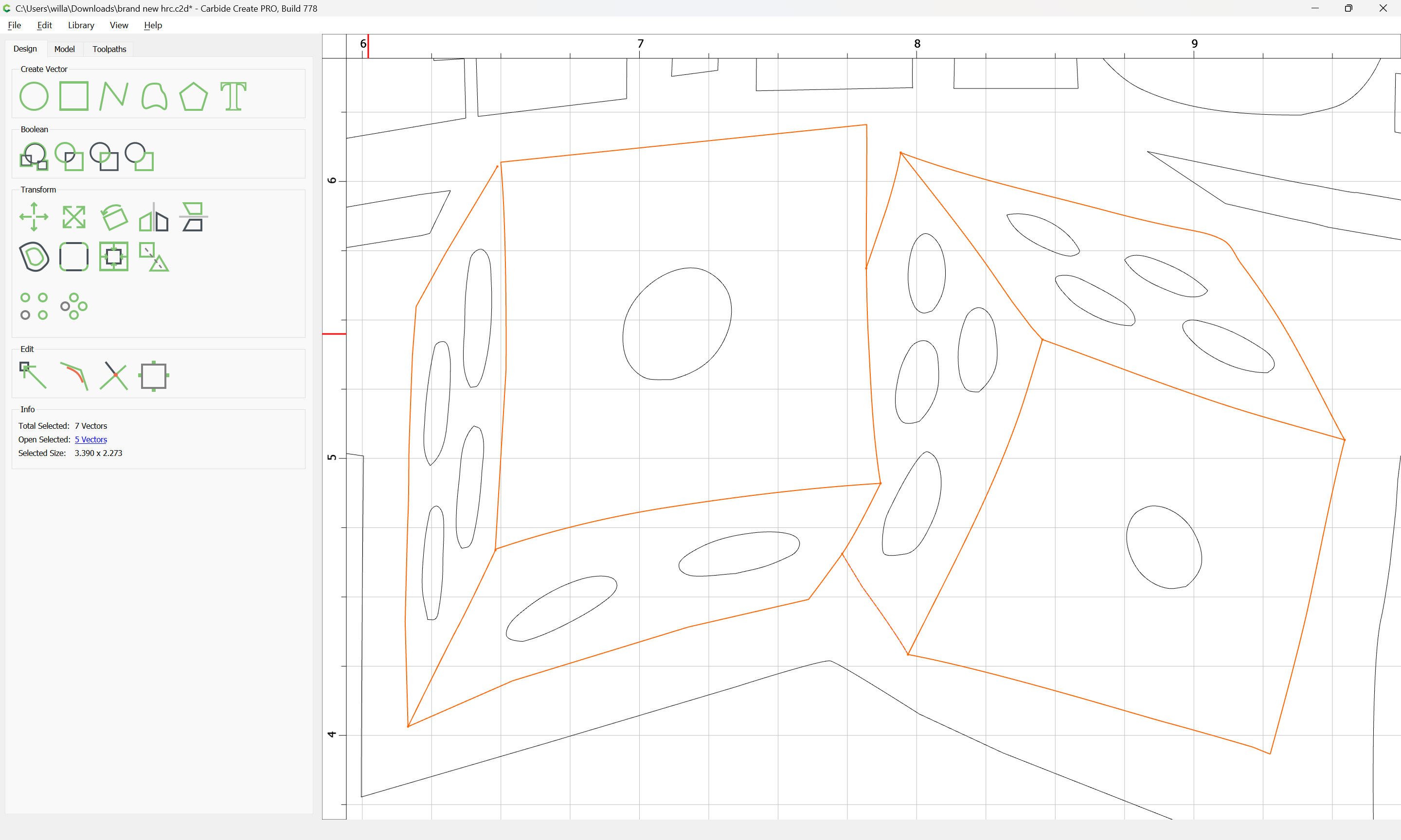
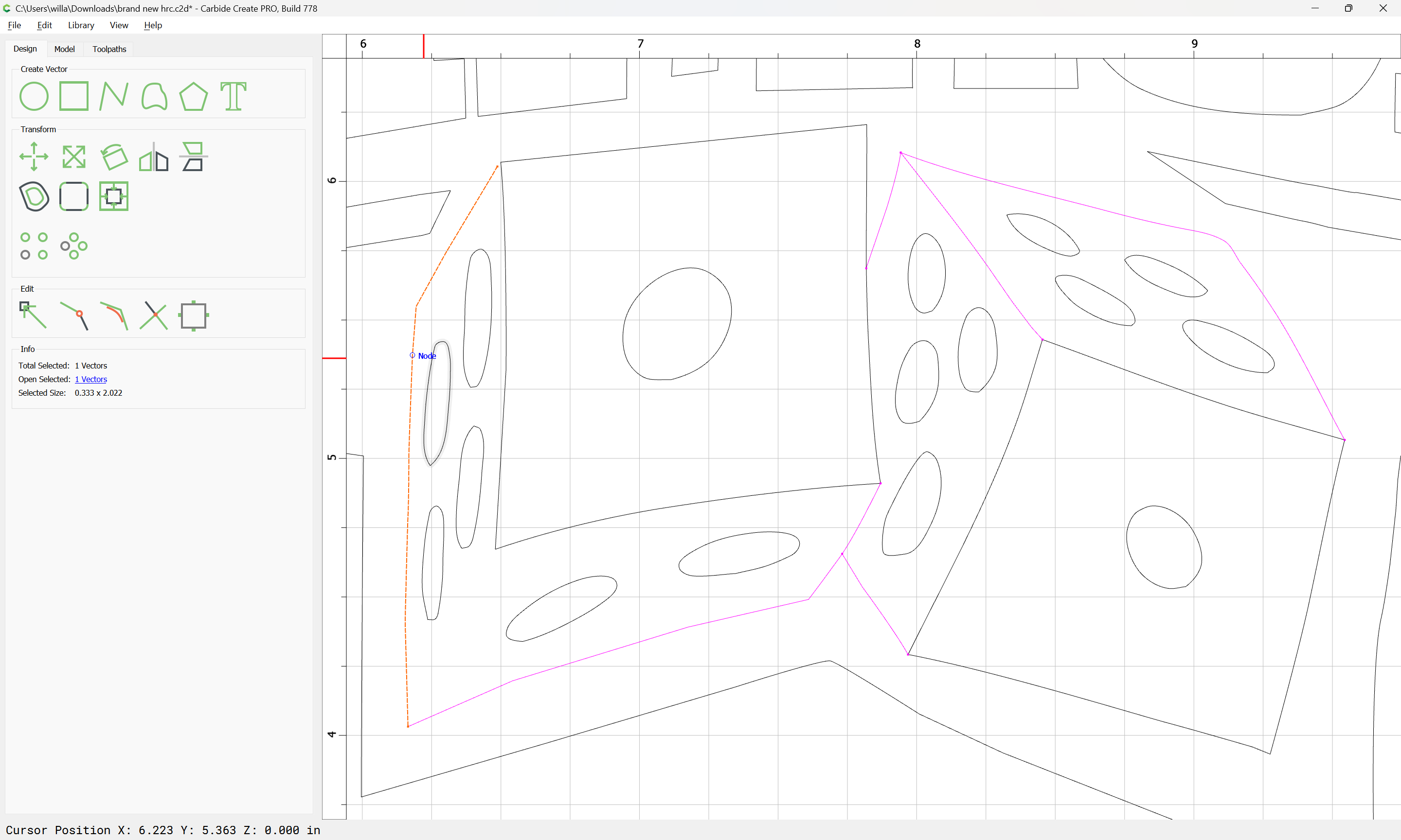
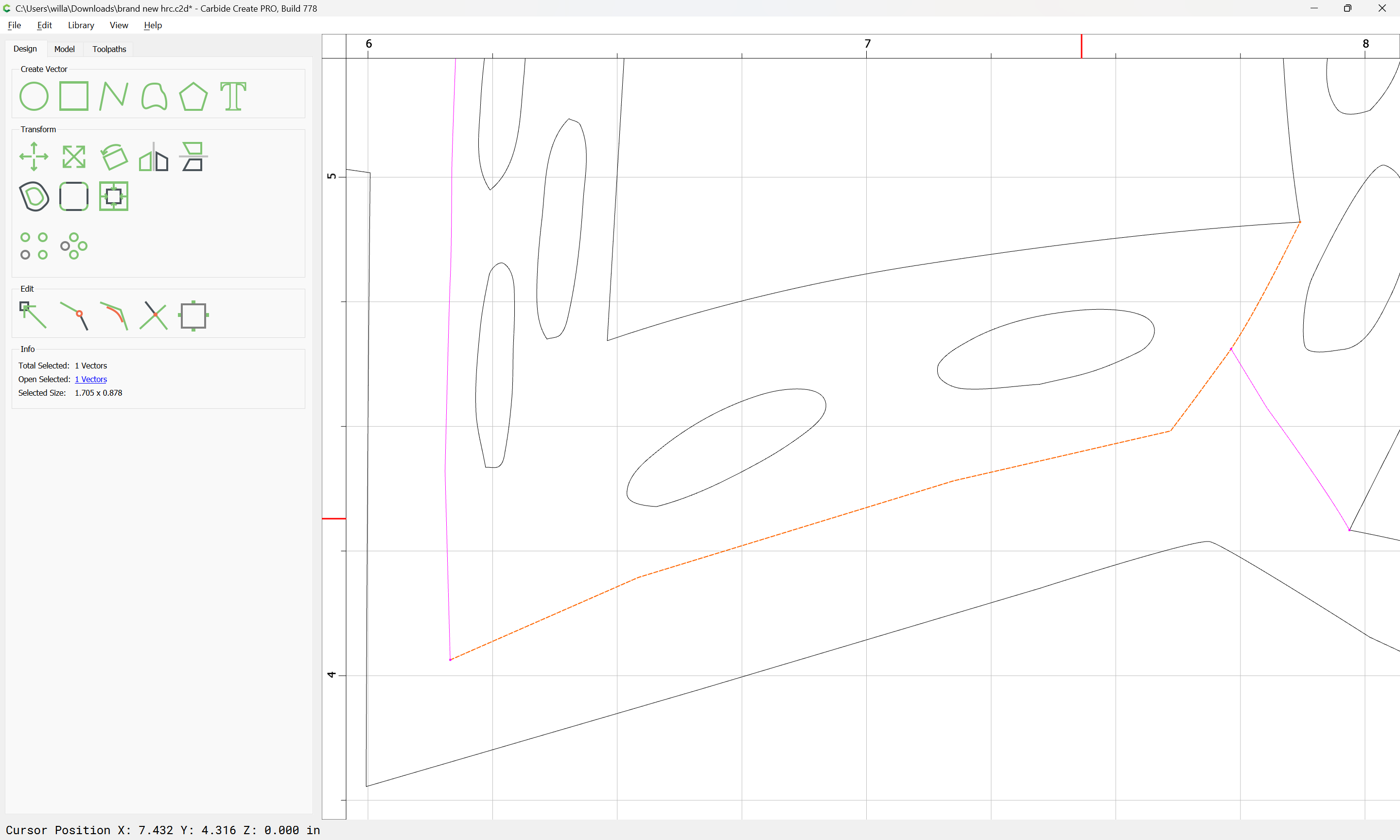
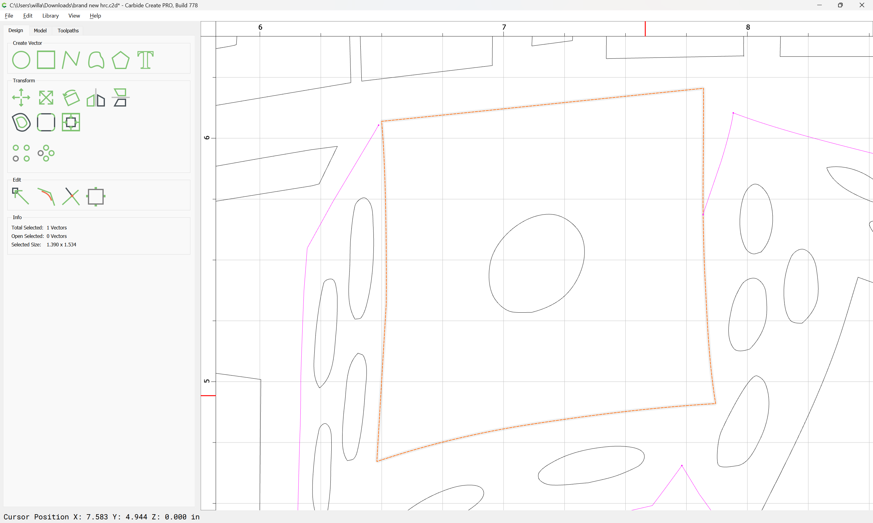
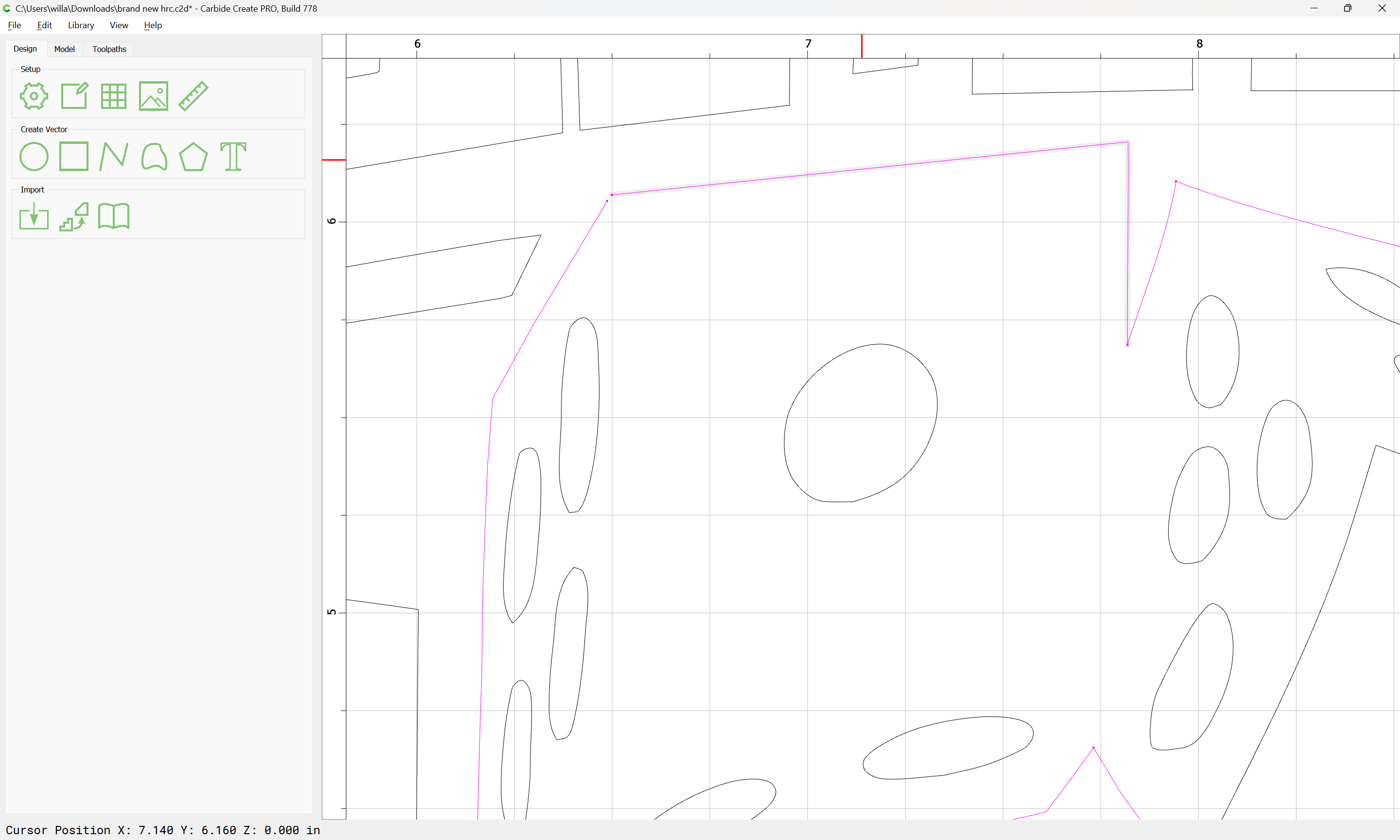
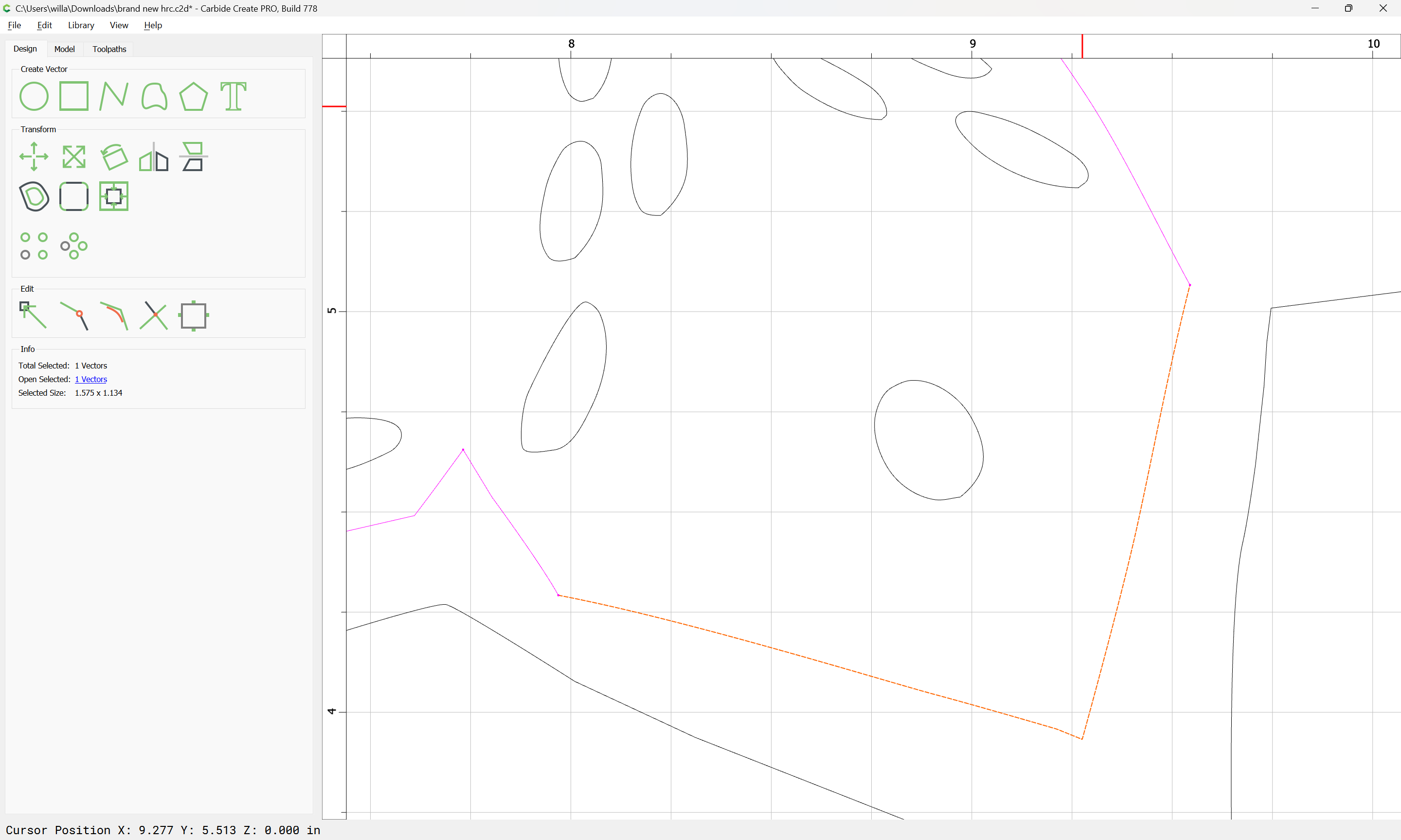
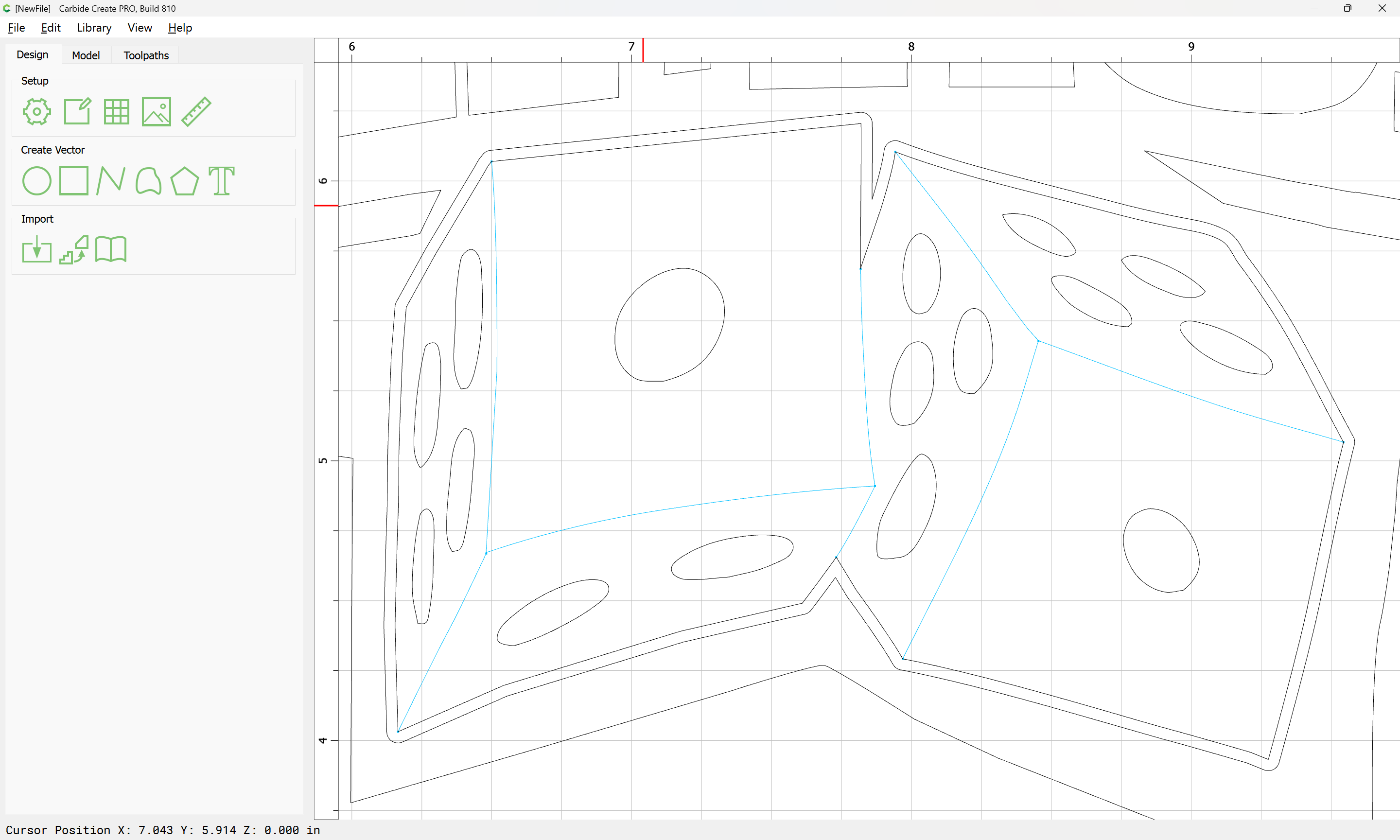
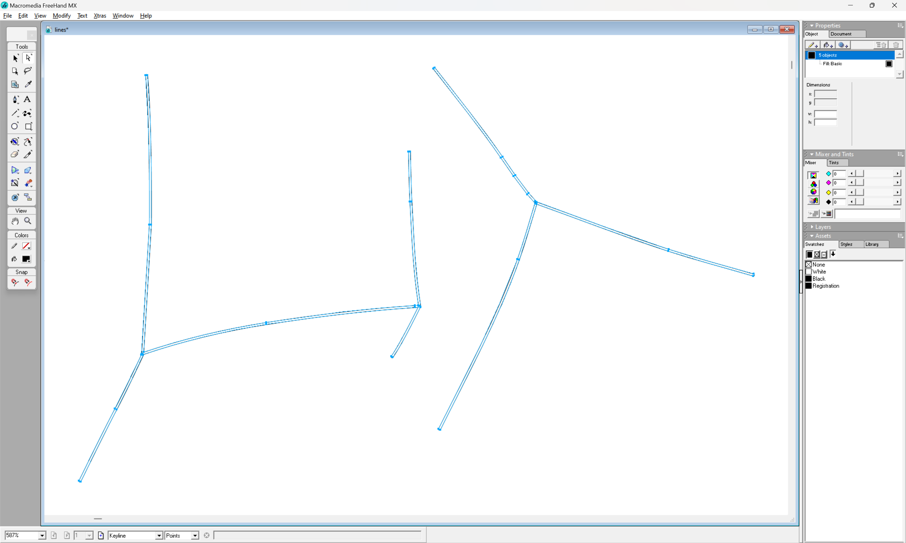
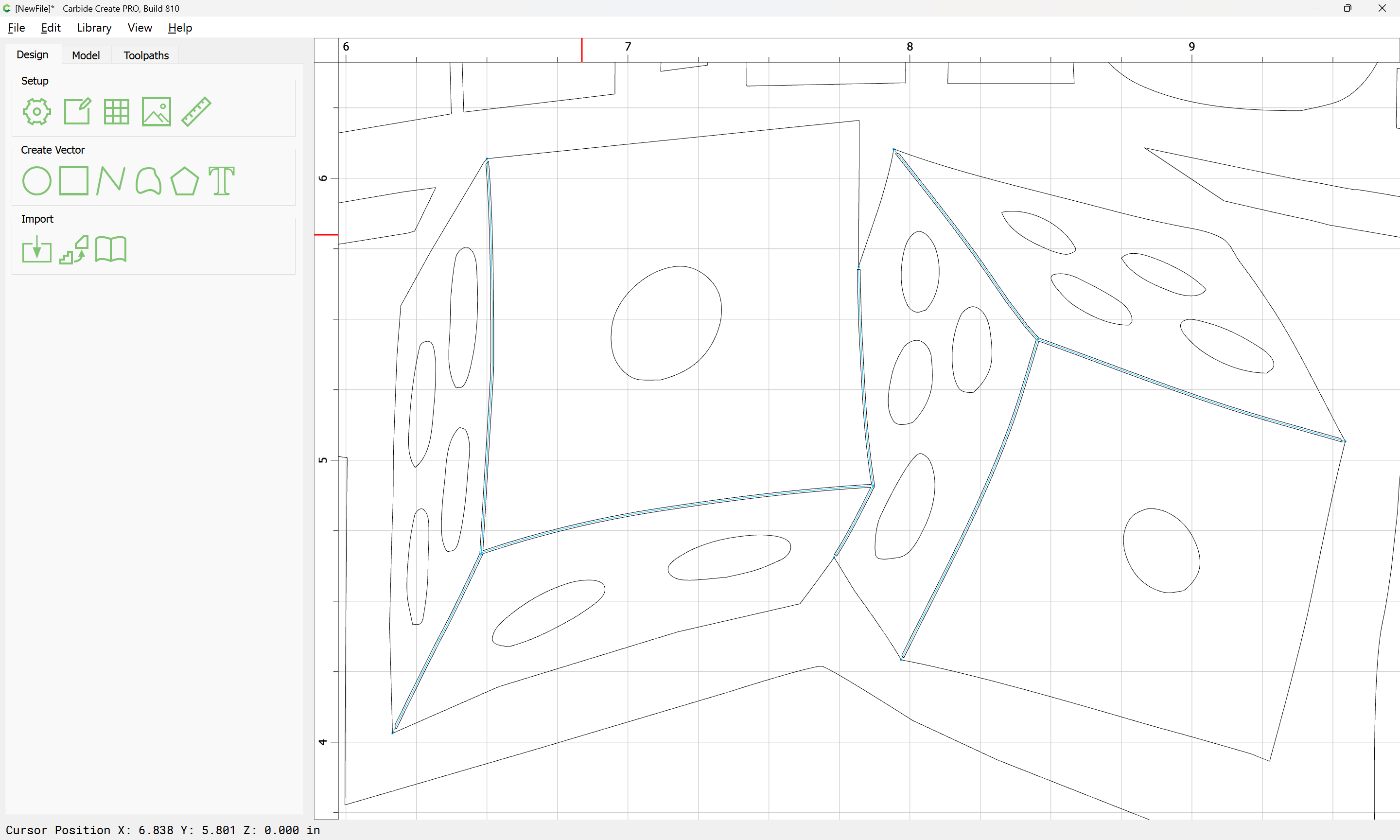
The geometry in question is:

and this raises the matter of having a closed region which also describes the 6 visible surfaces of the two dice.
Start by duplicating the geometry in place:
and making a Reference layer:
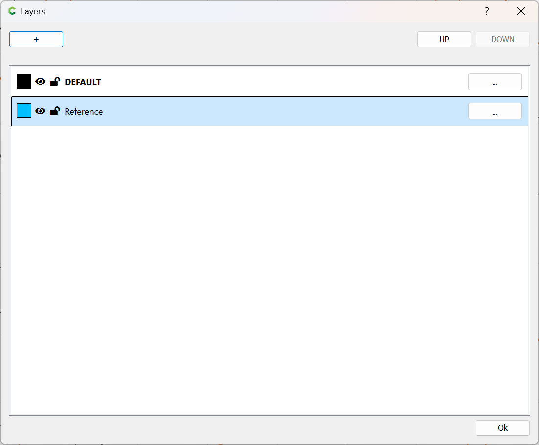
moving the duplicate to that layer, and locking it.
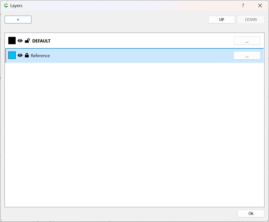
and hiding it:
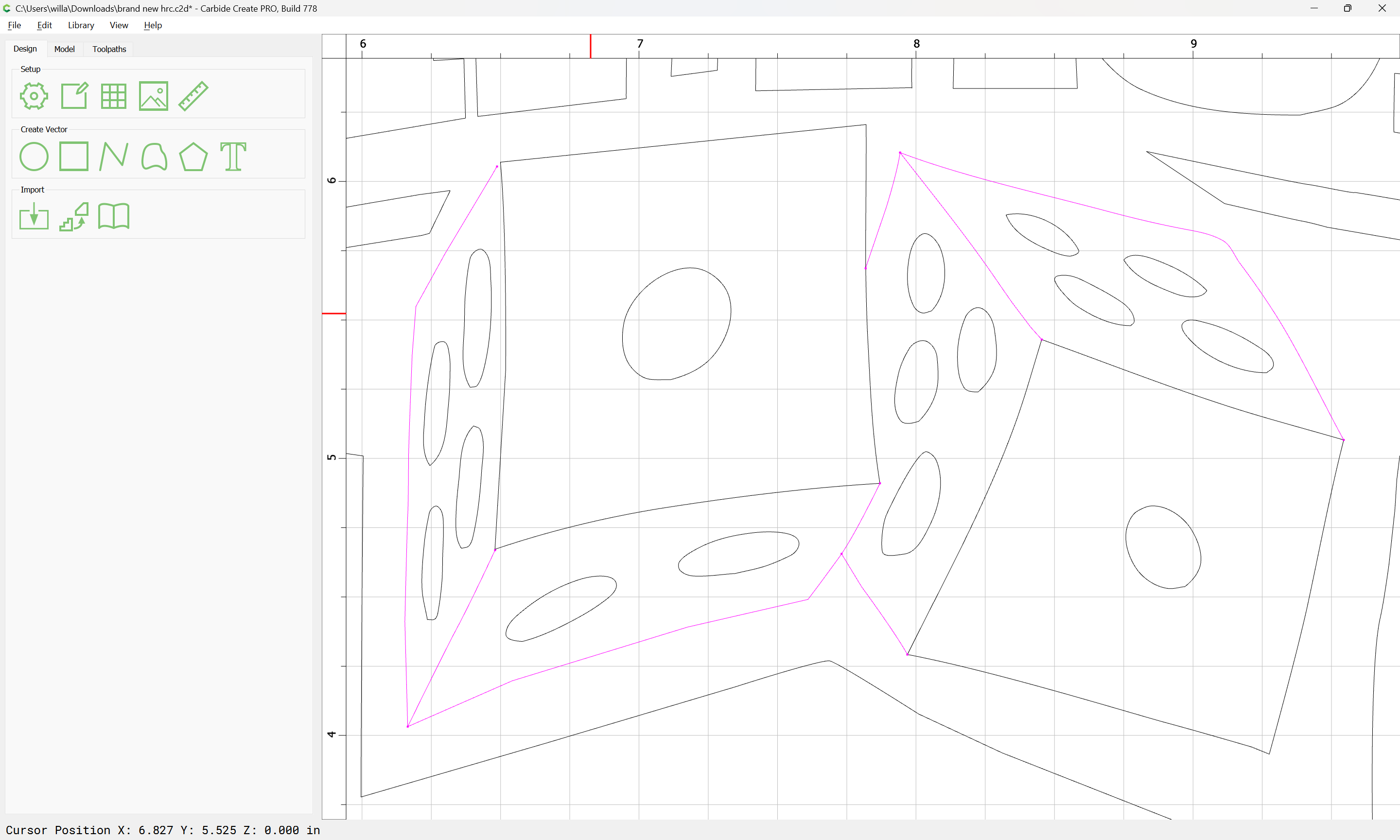
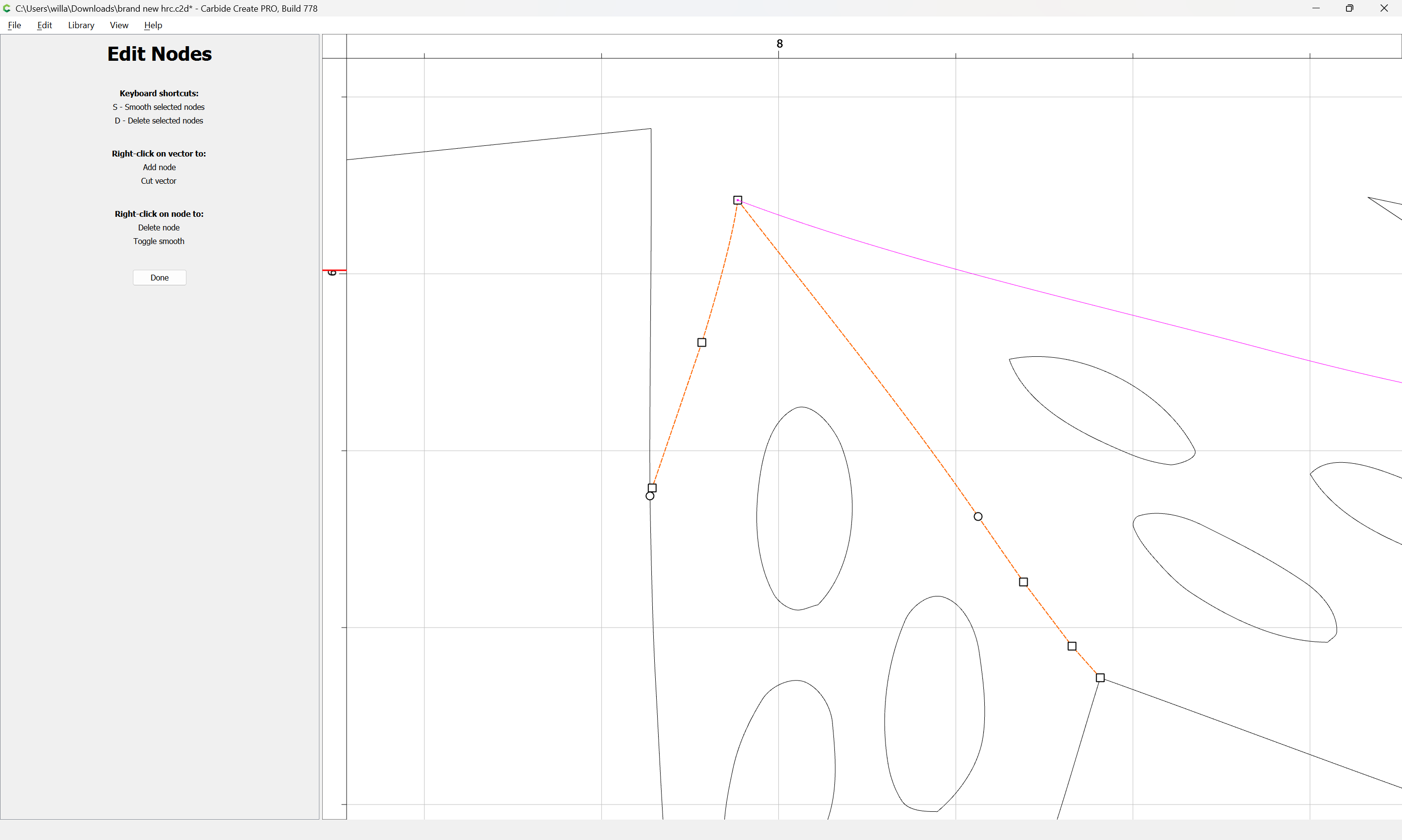
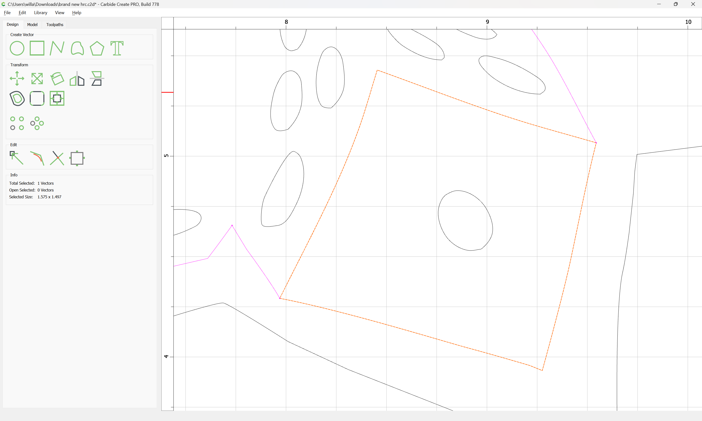
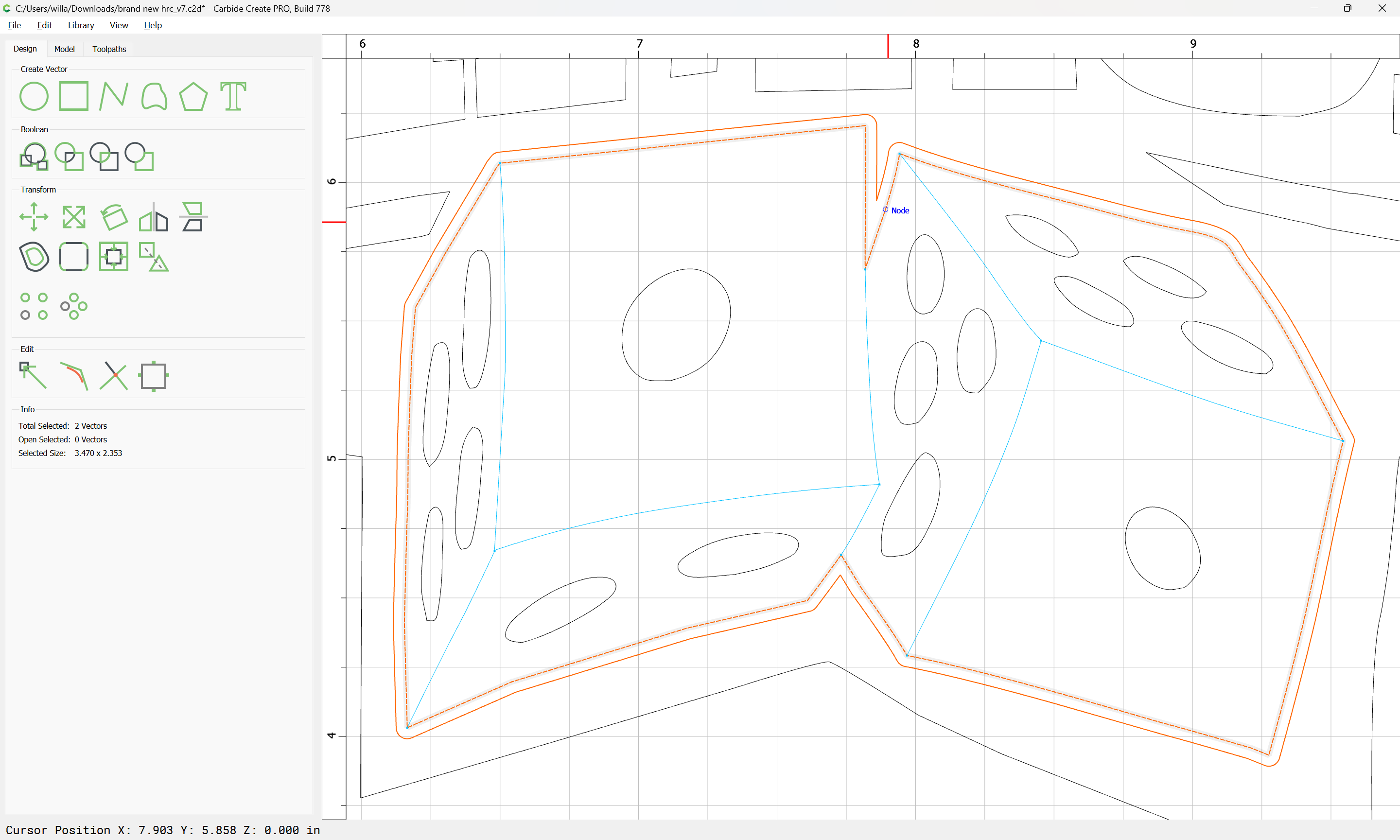
First, to get the closed region, delete the unnecessary lines (they can be retrieved from the reference layer when needed later):
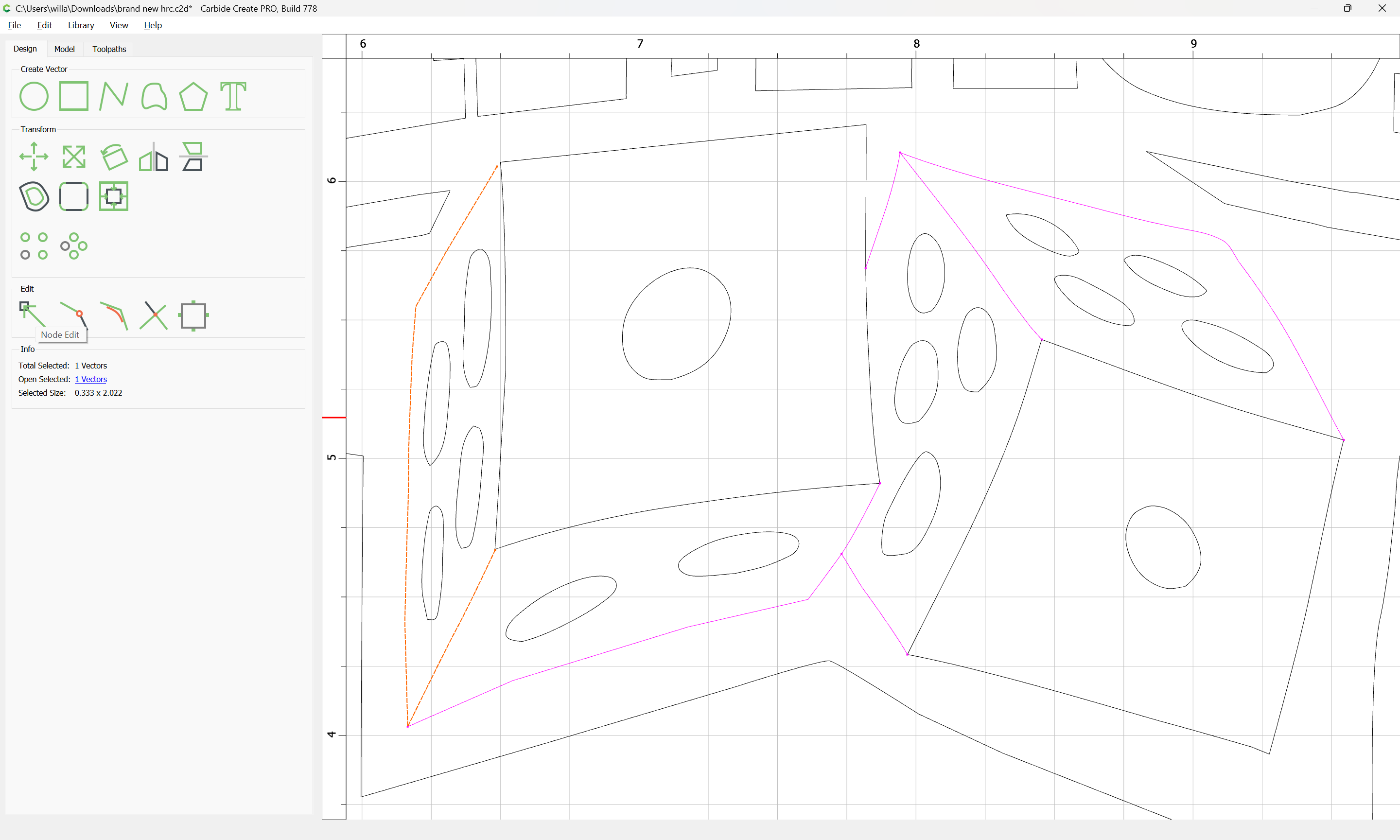
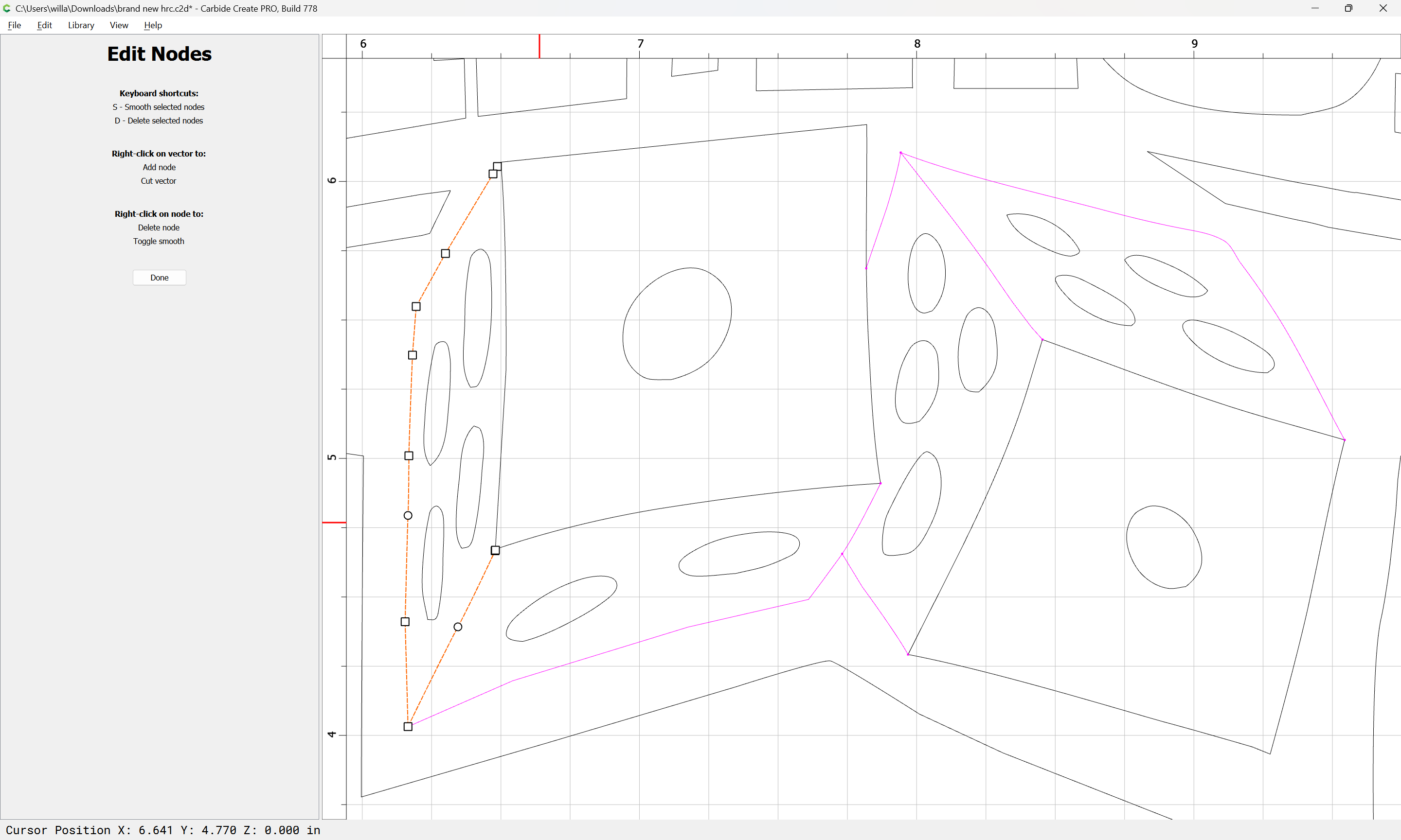
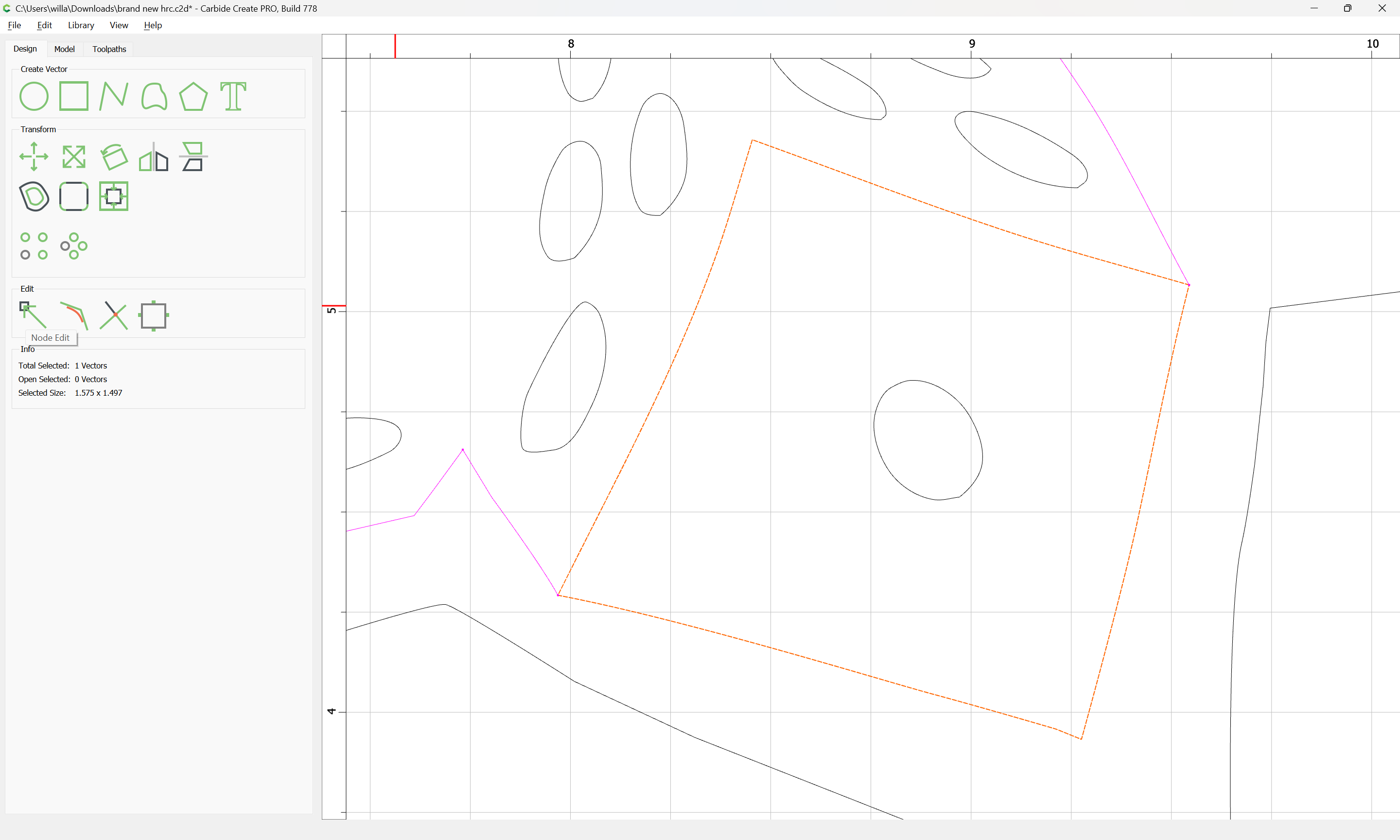
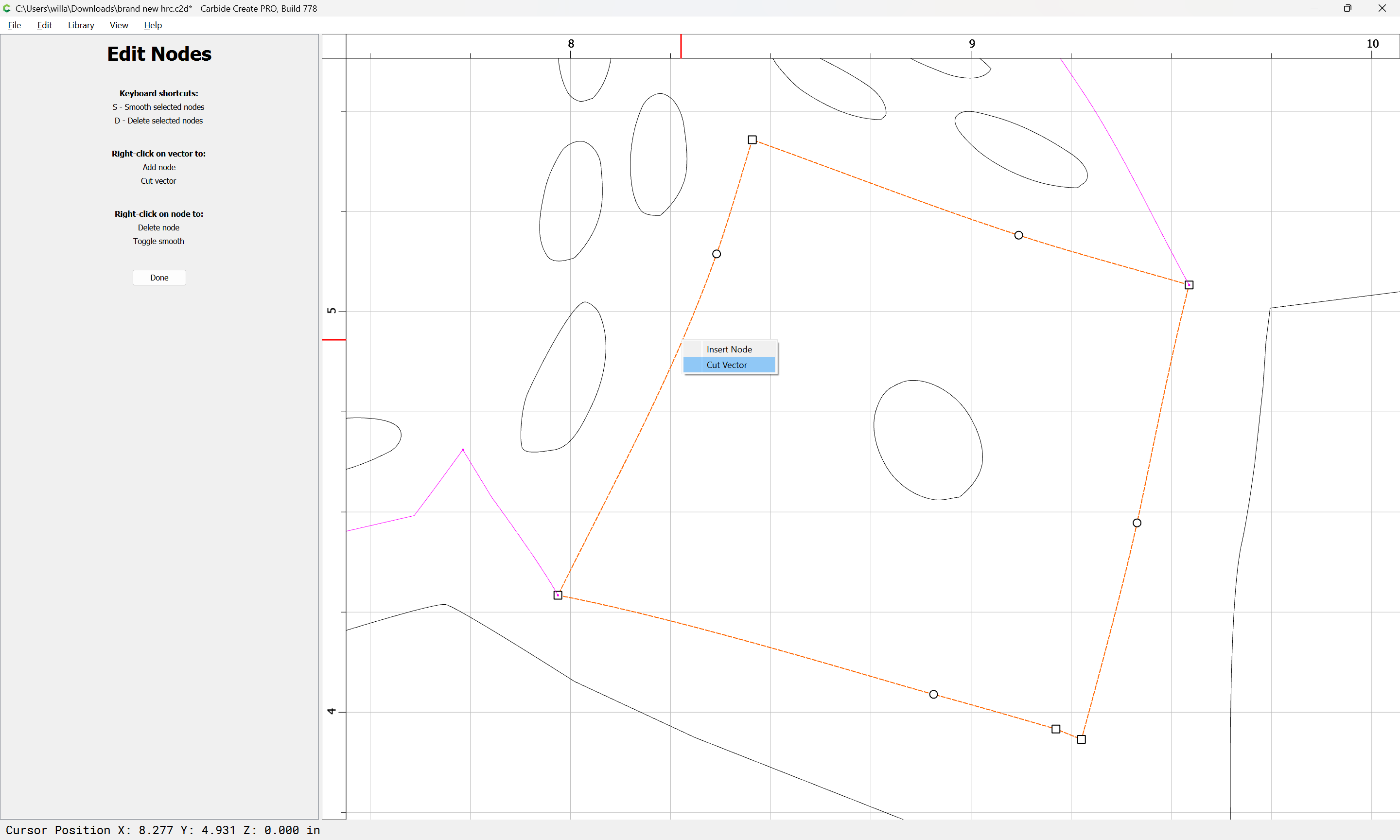
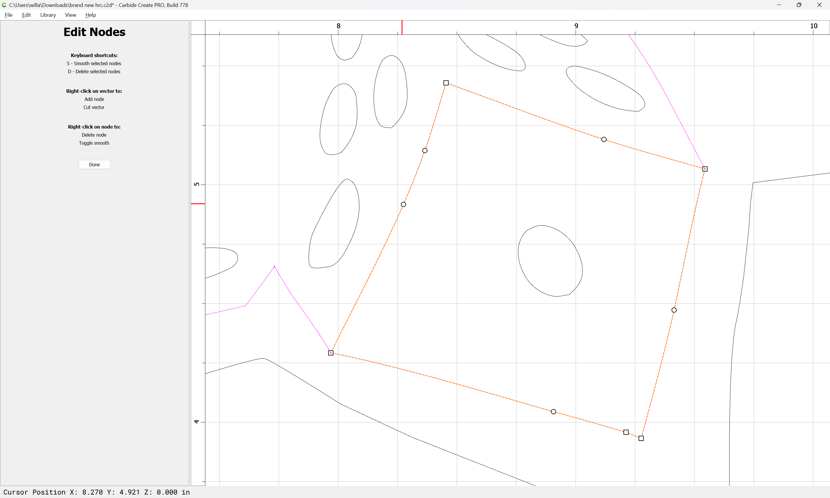
Since the lines in question are joined with the perimeter, it will be necessary to use Node Editing:

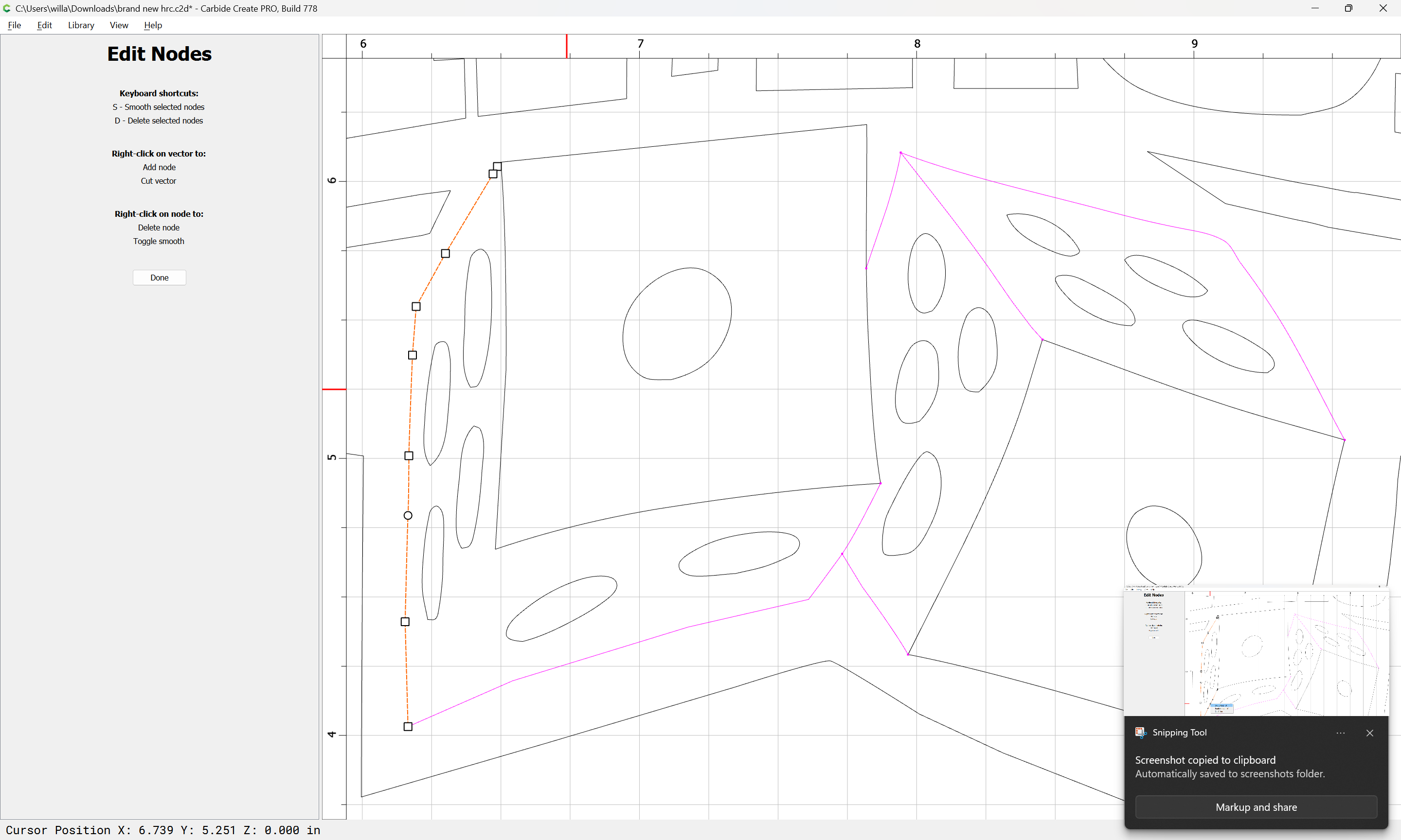
Done
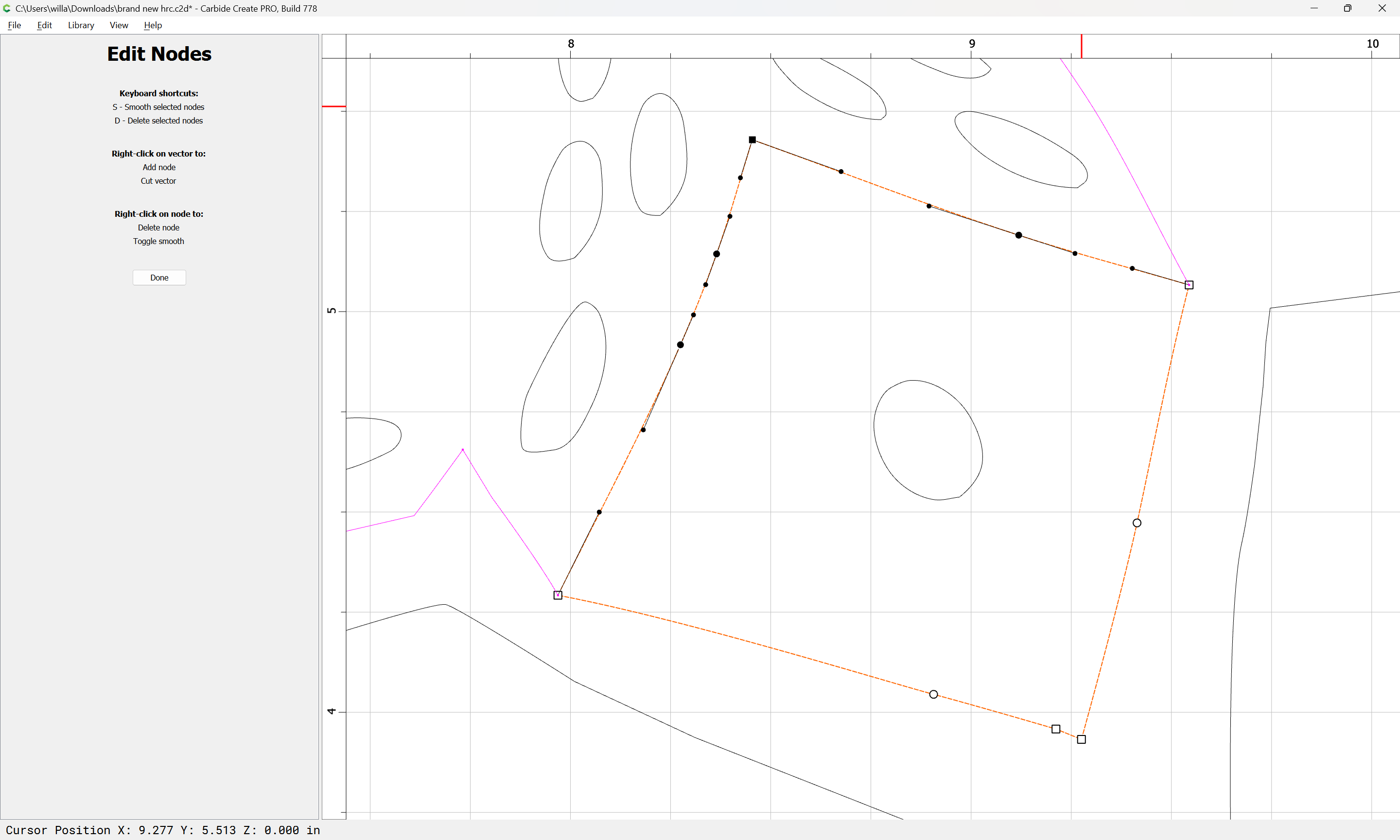
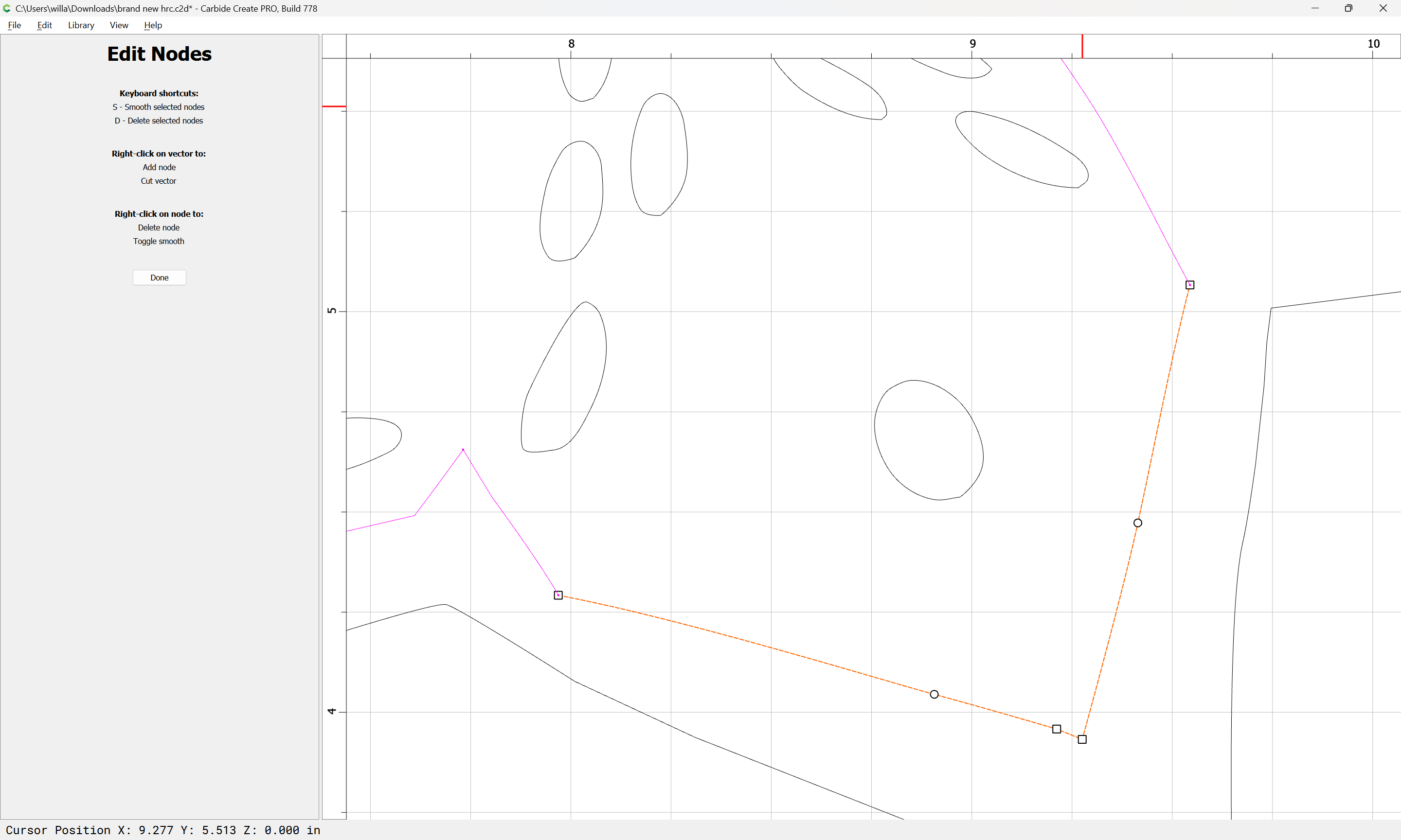
Repeat for the other interior lines:
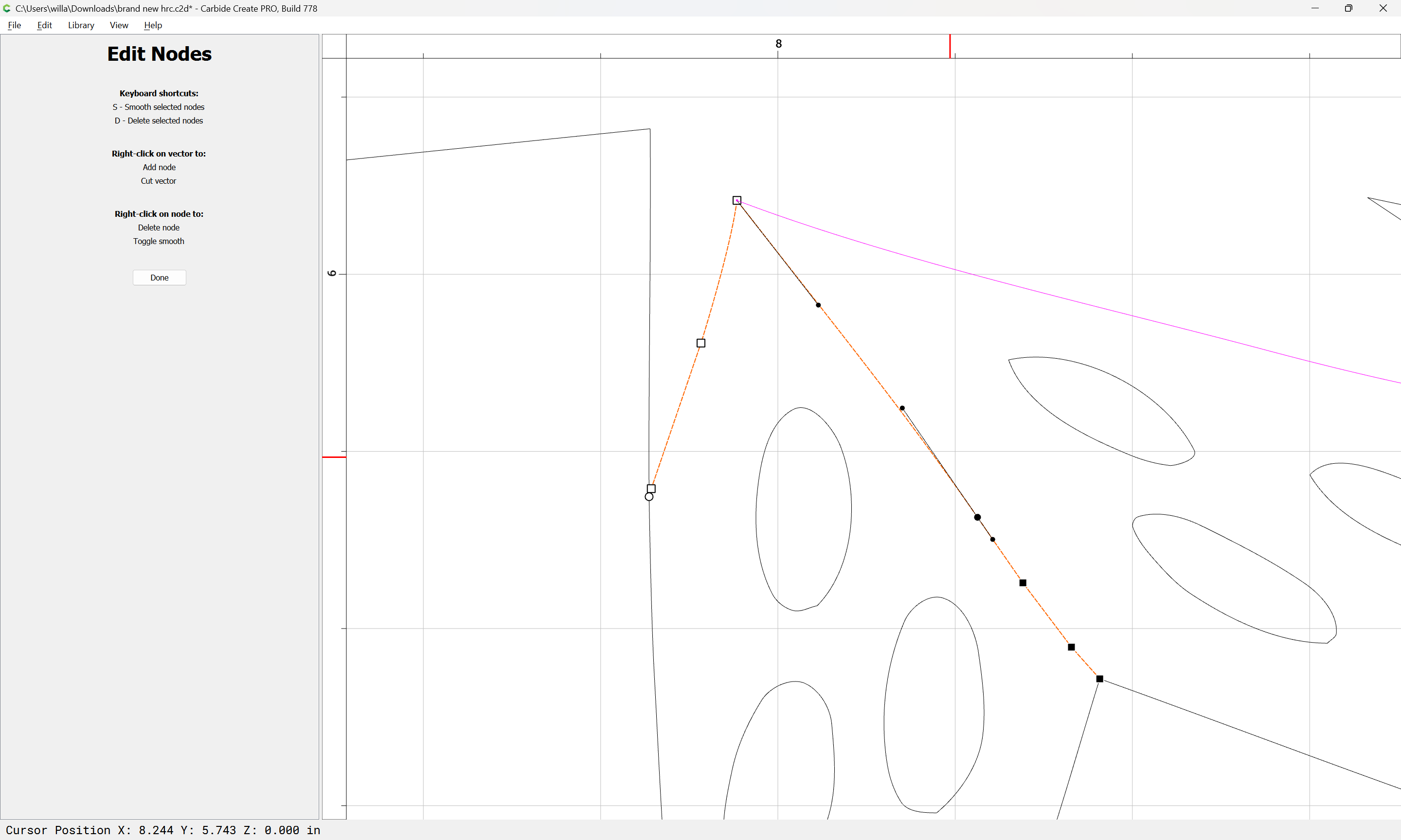
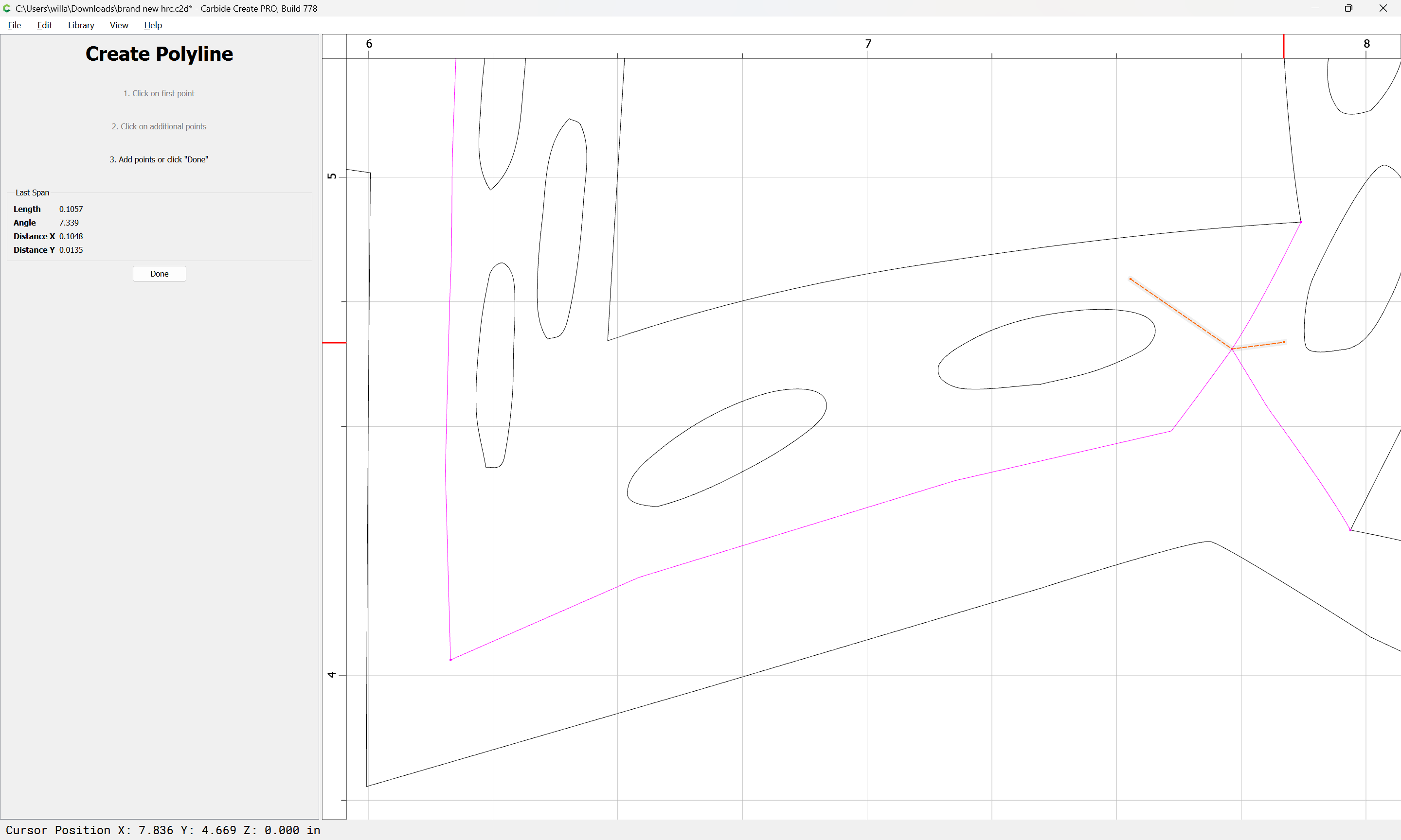
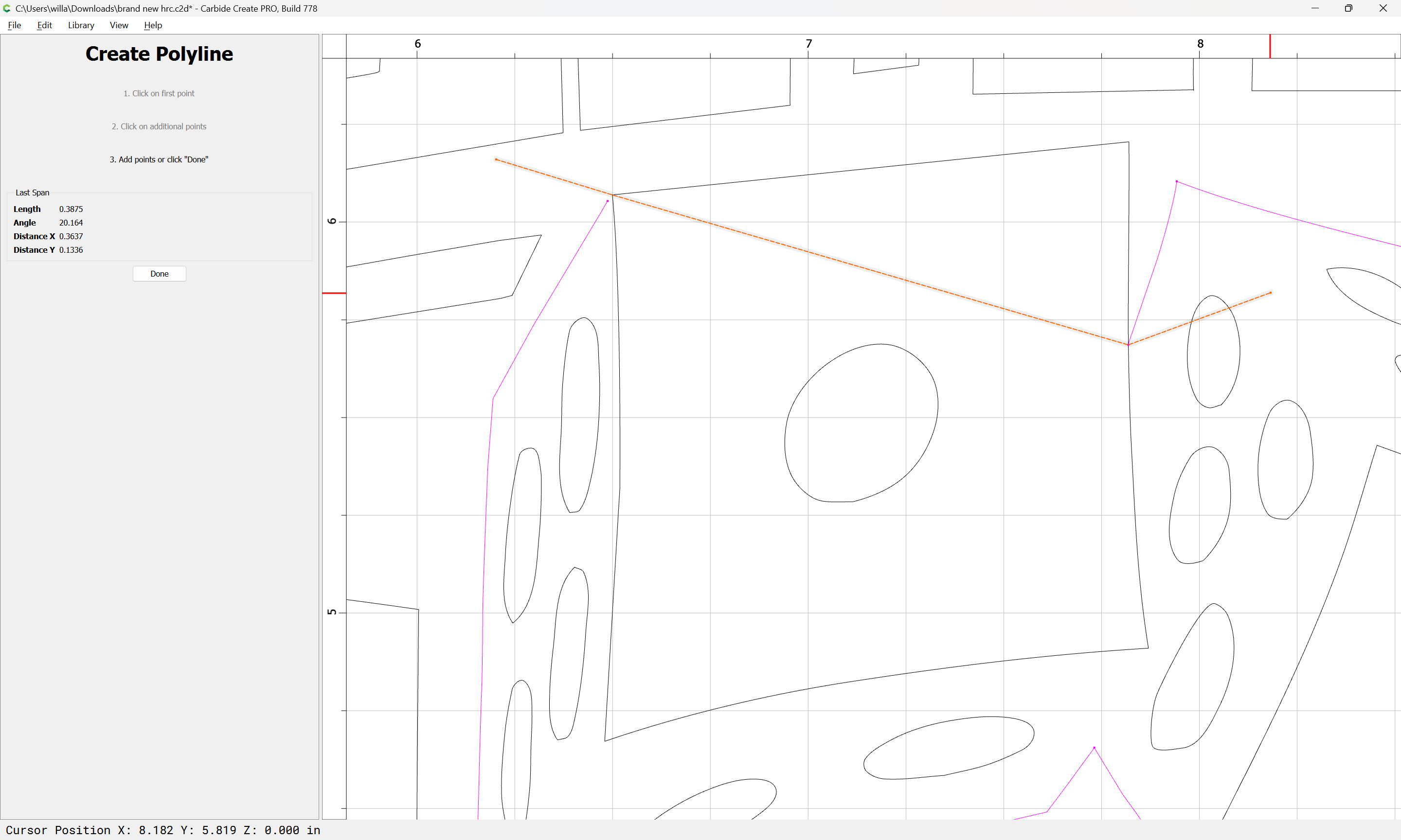
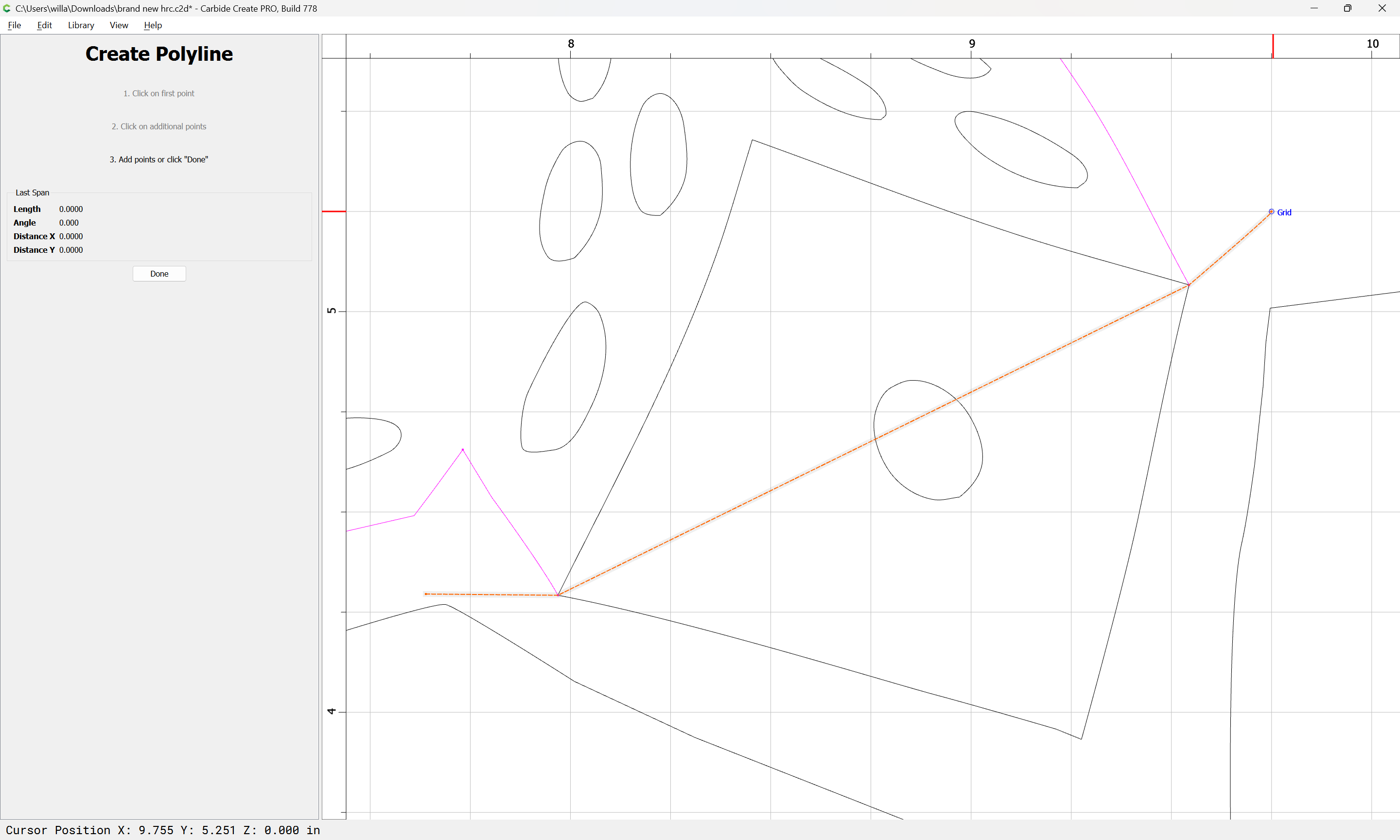
For lines which need to be shortened:
Draw in geometry which describes there the cut should be made:

Done
i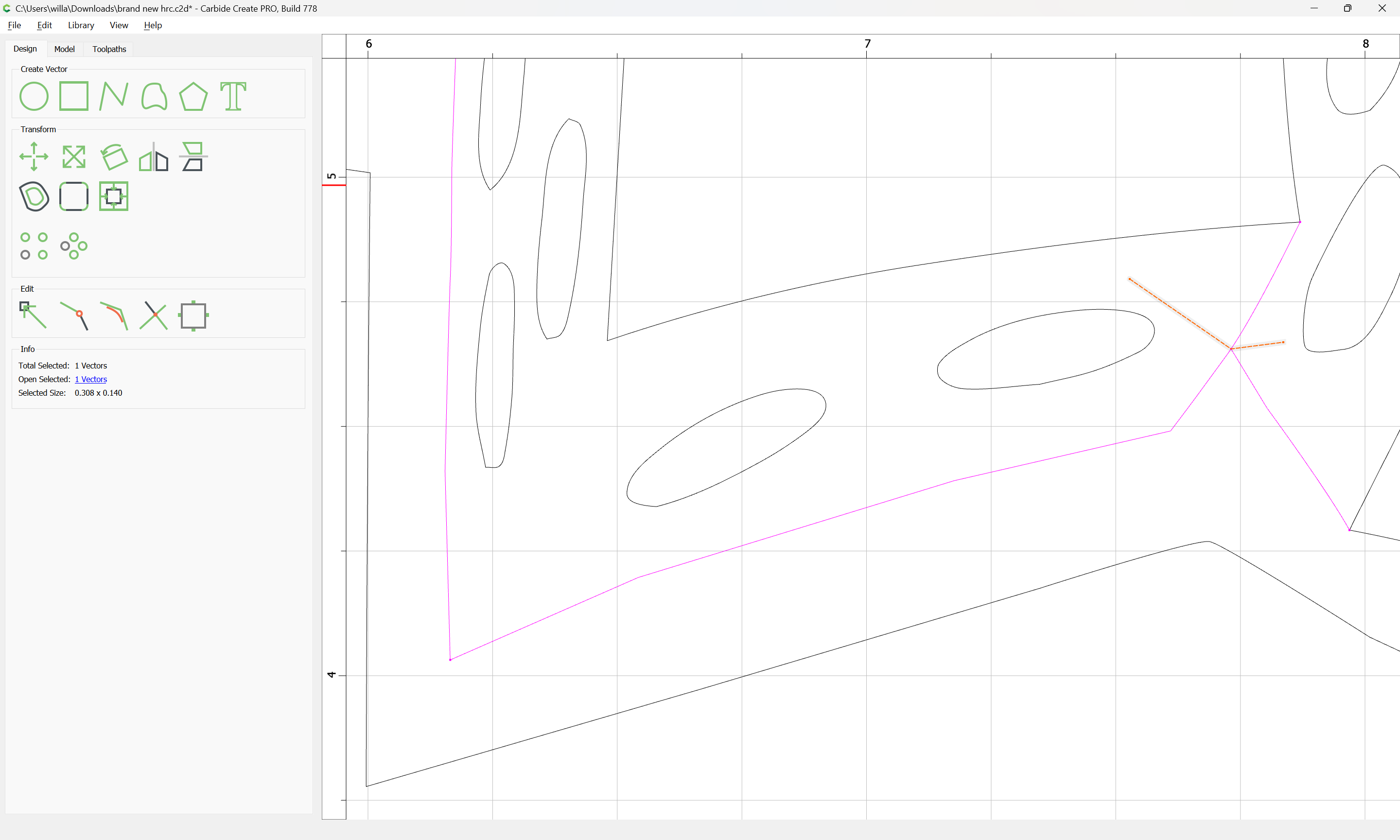
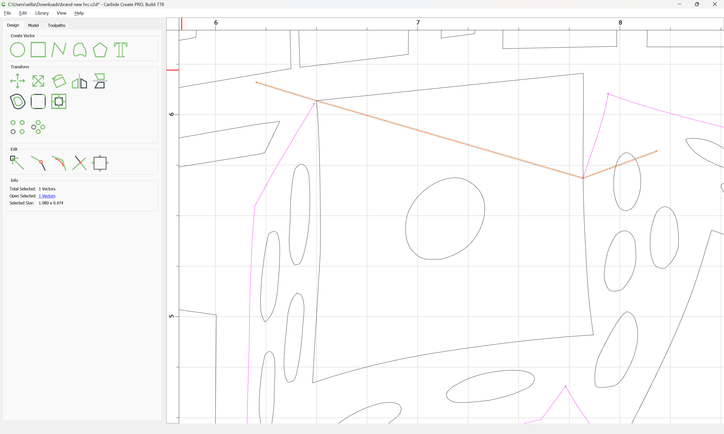
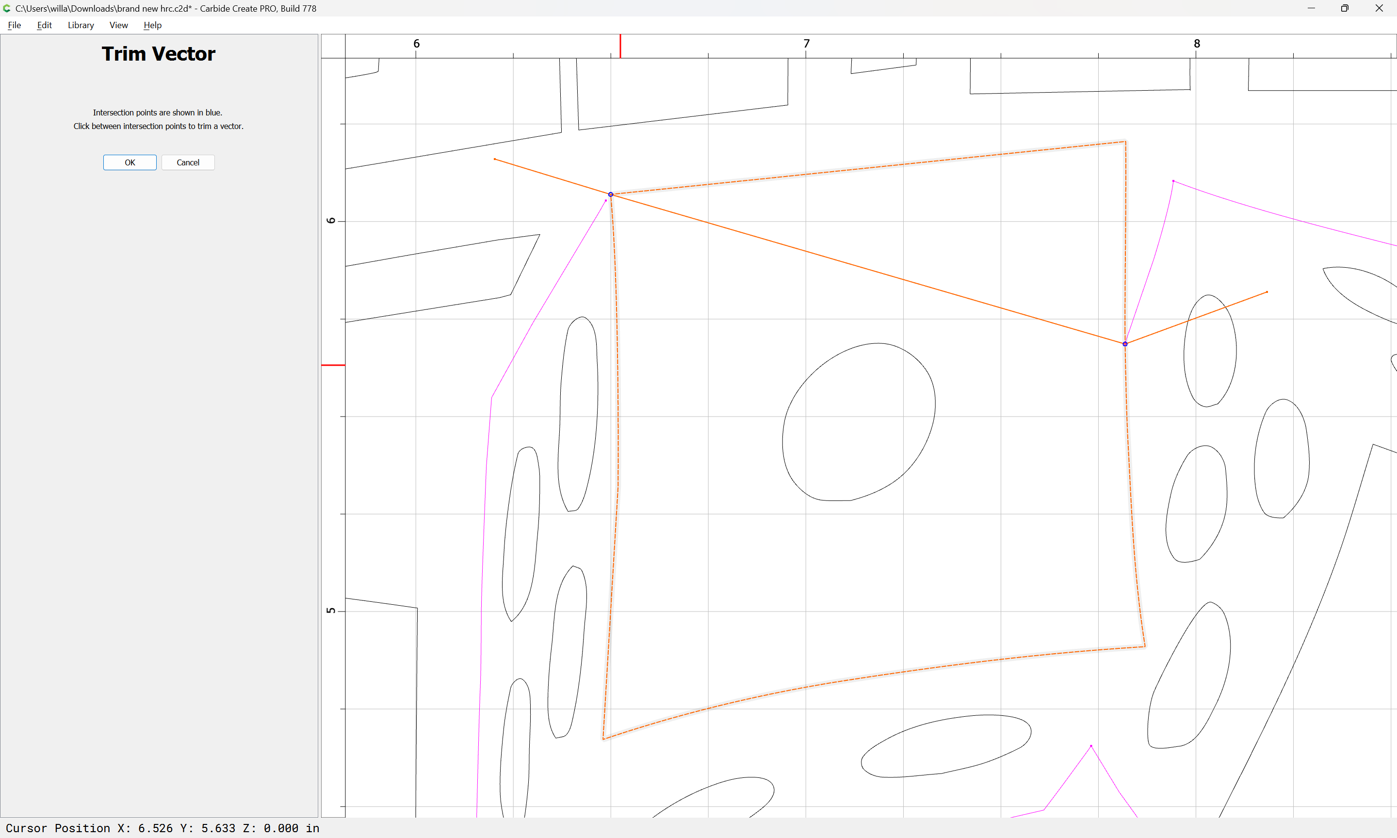
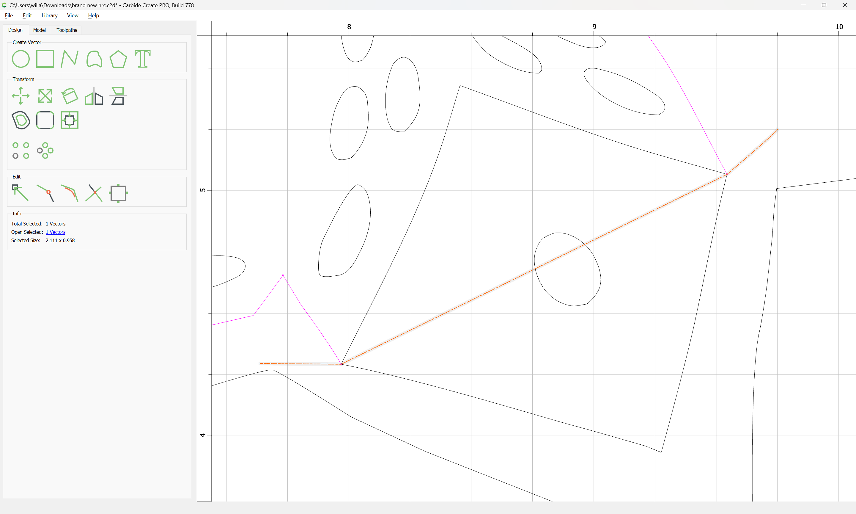
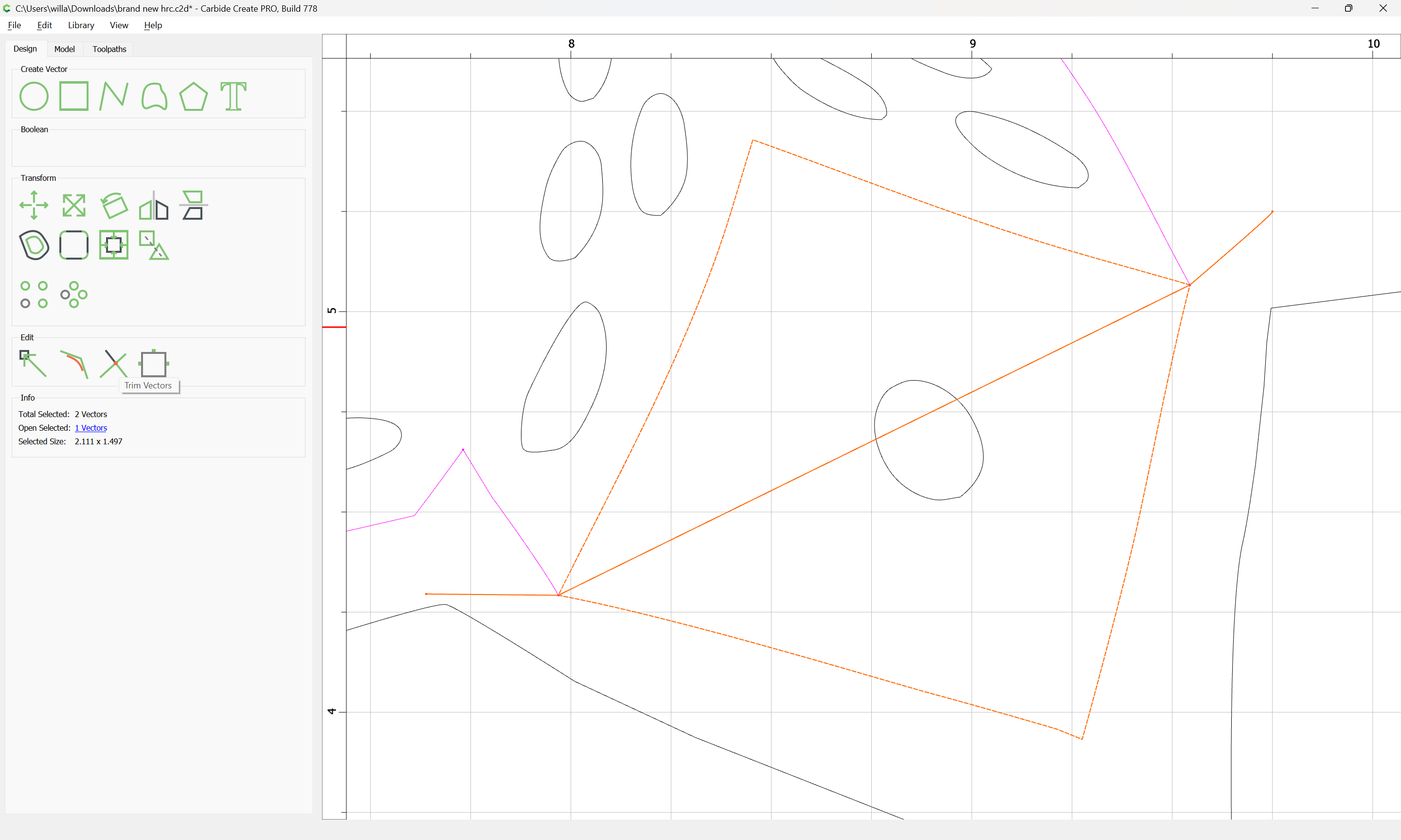
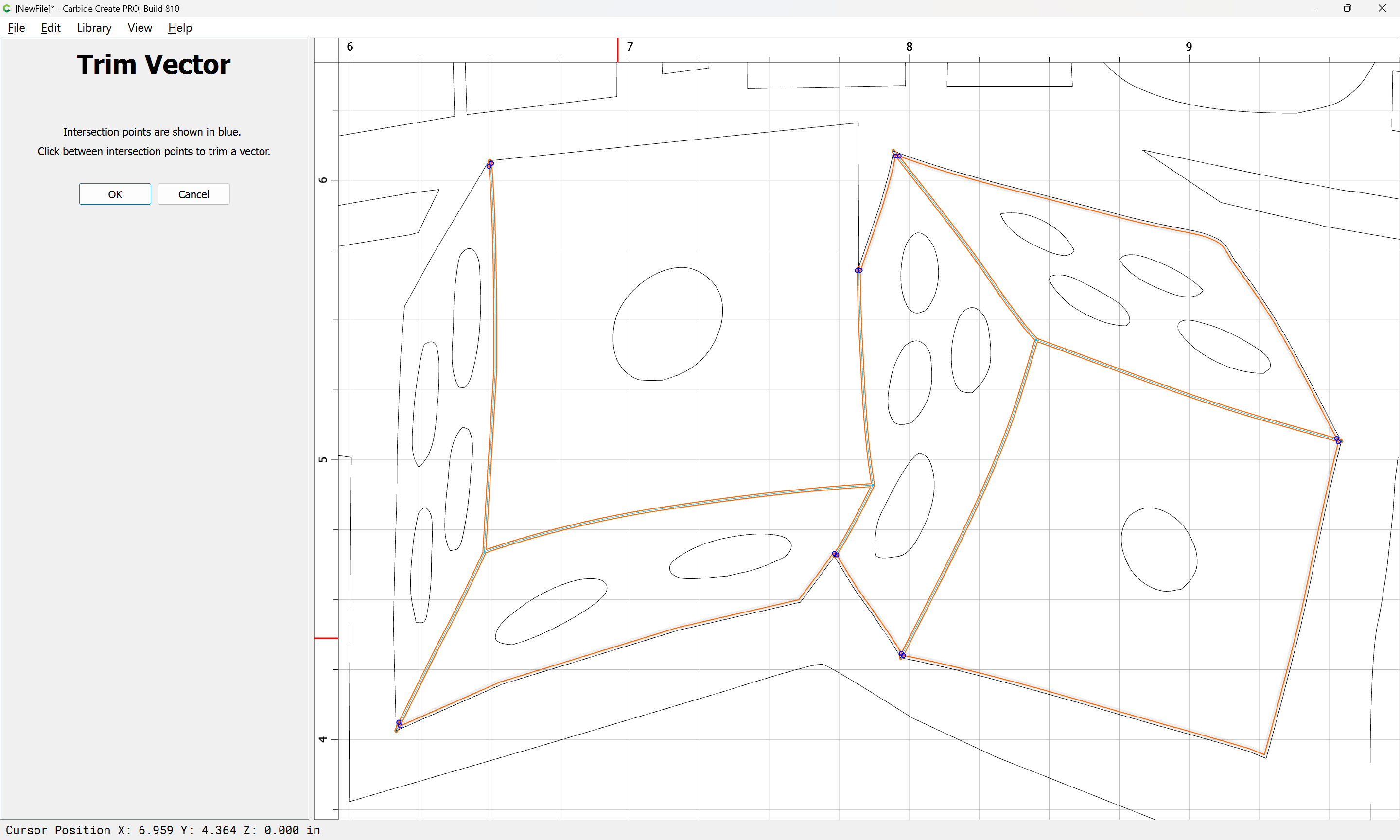
Select the line to be cut and the cut defining line:
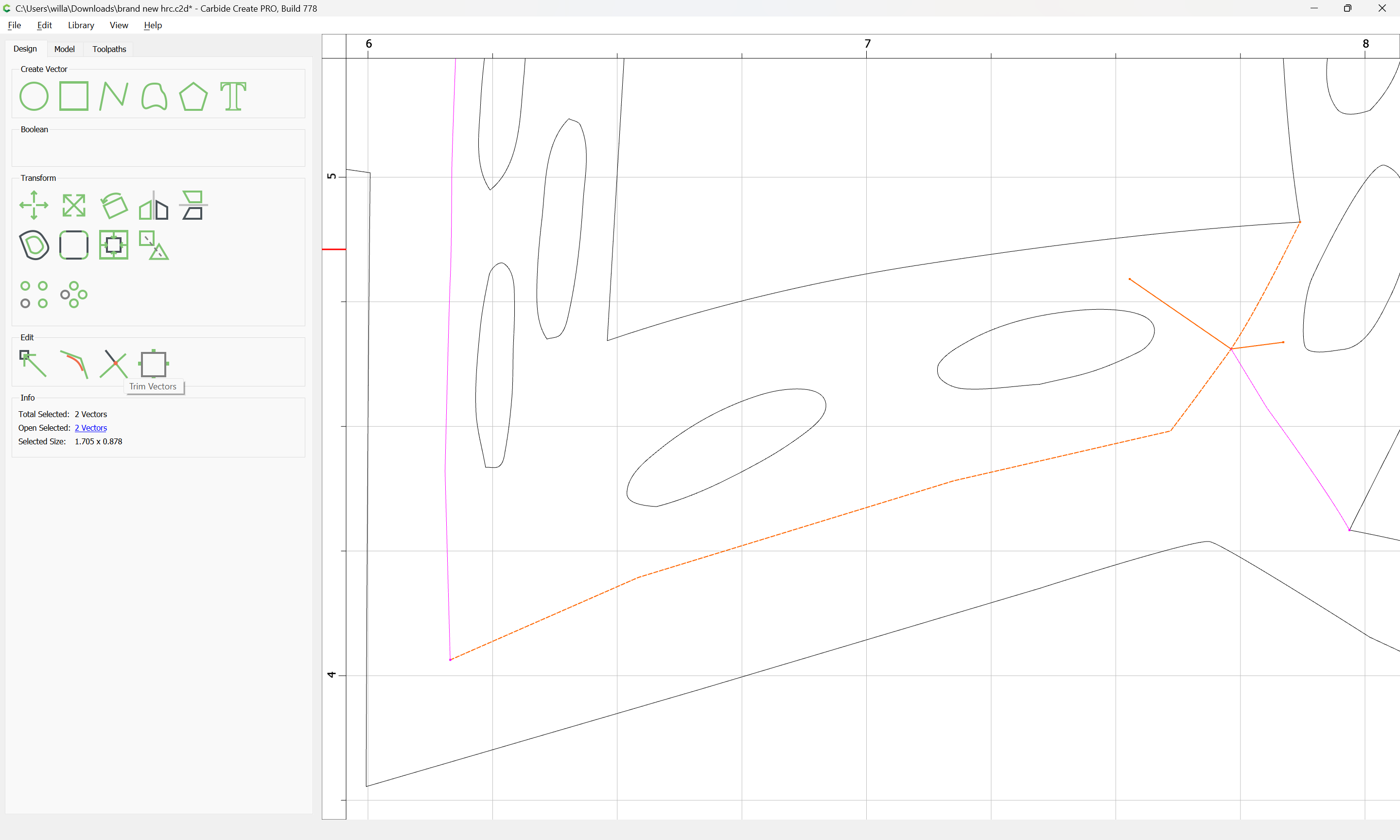
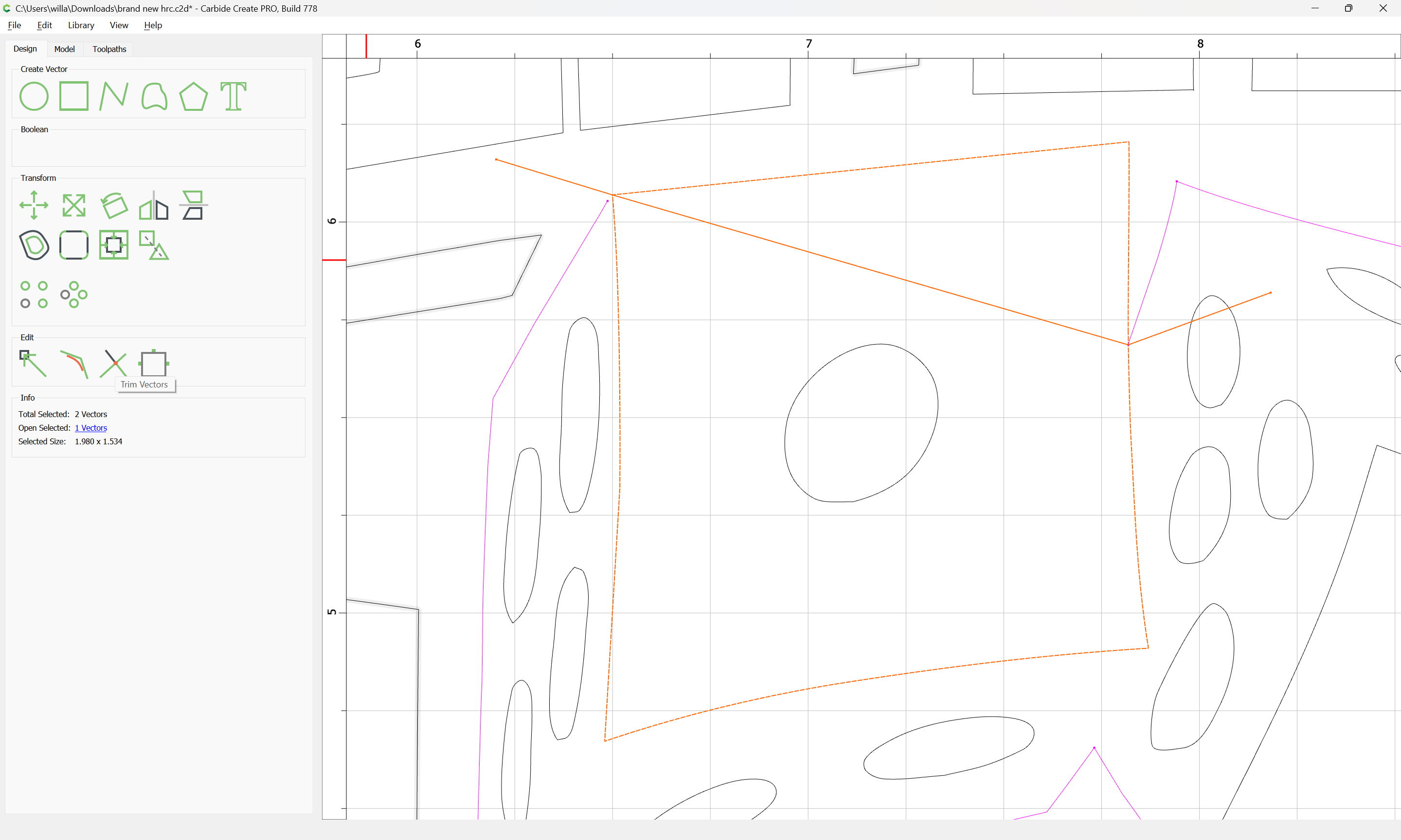
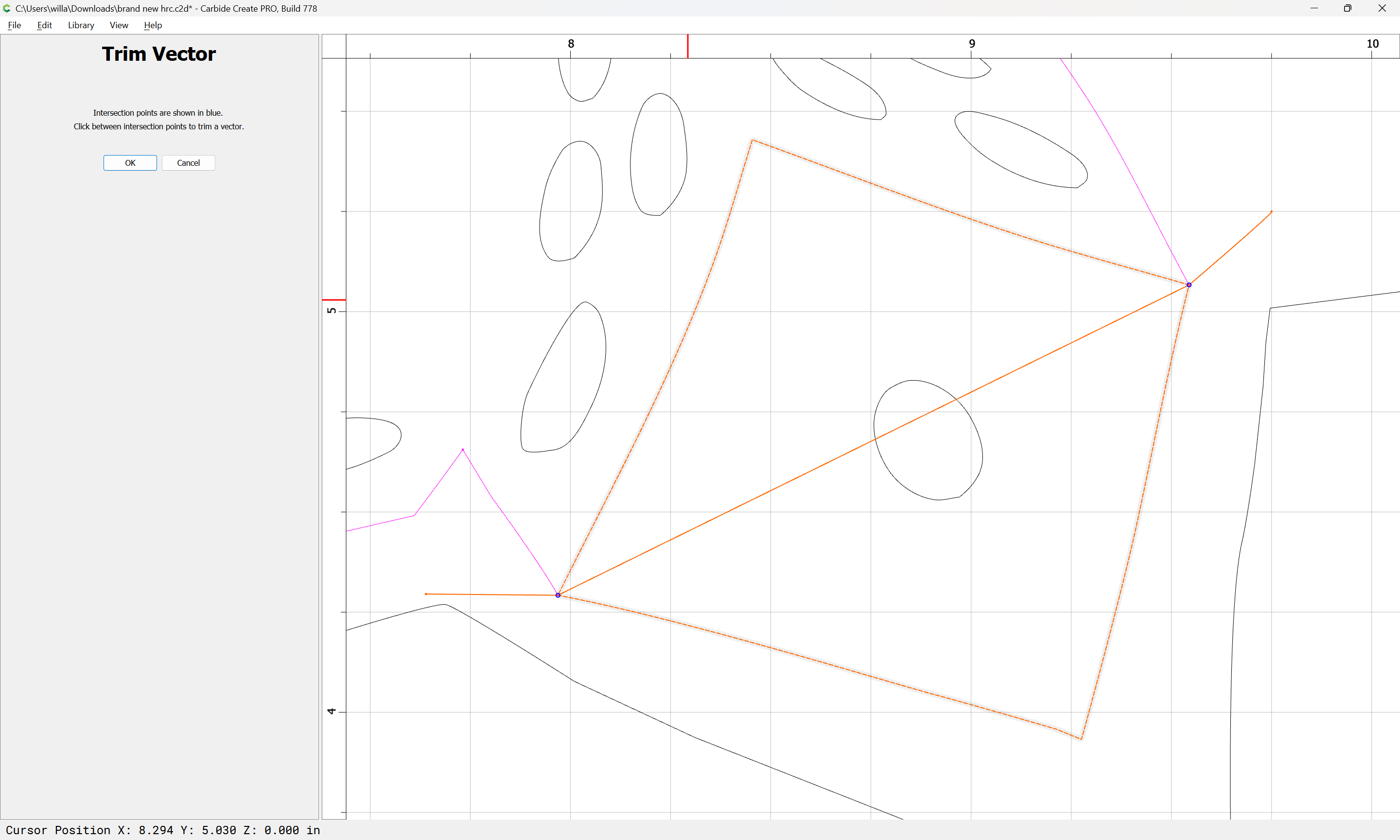
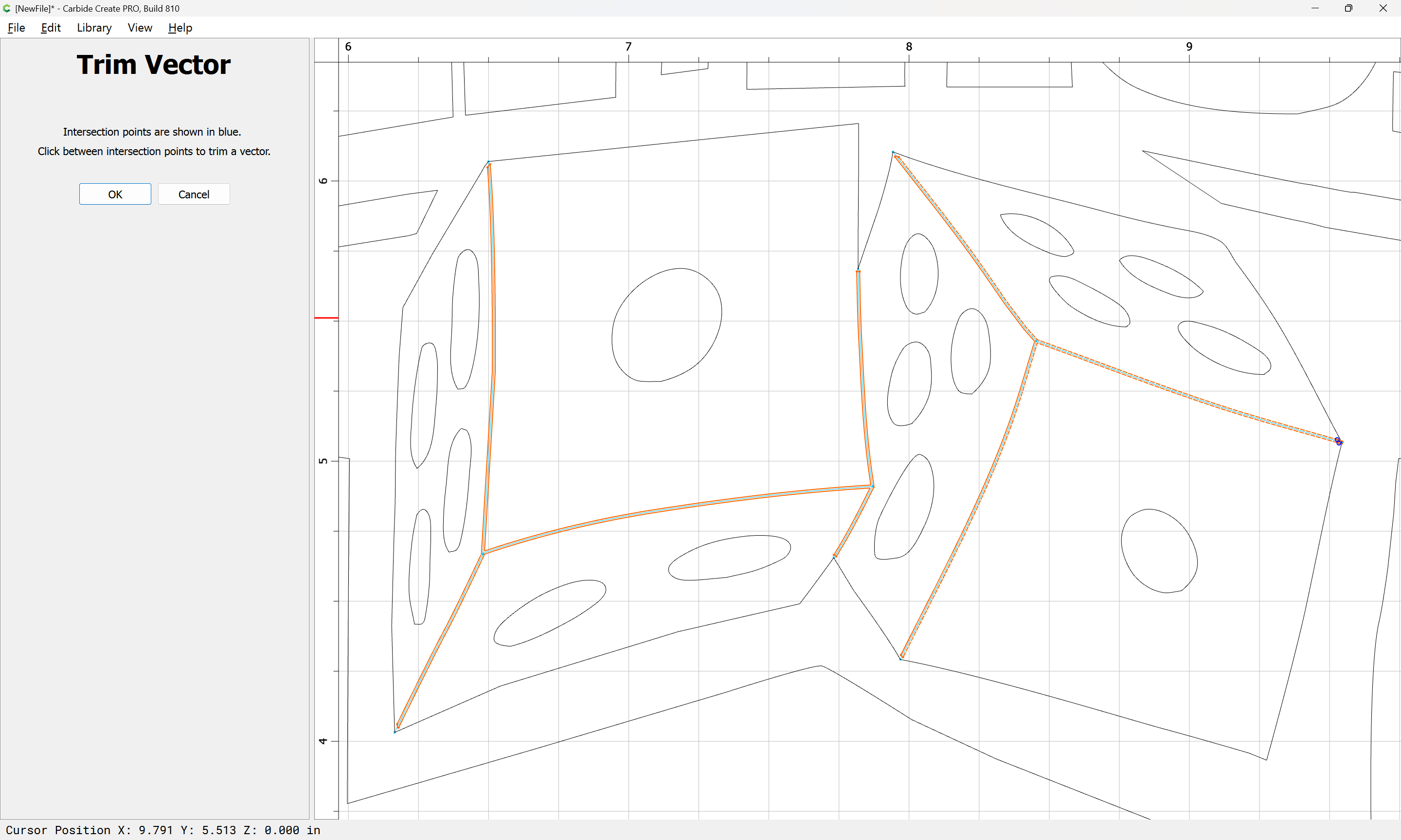
and use Trim Vectors:
to remove what is not wanted:
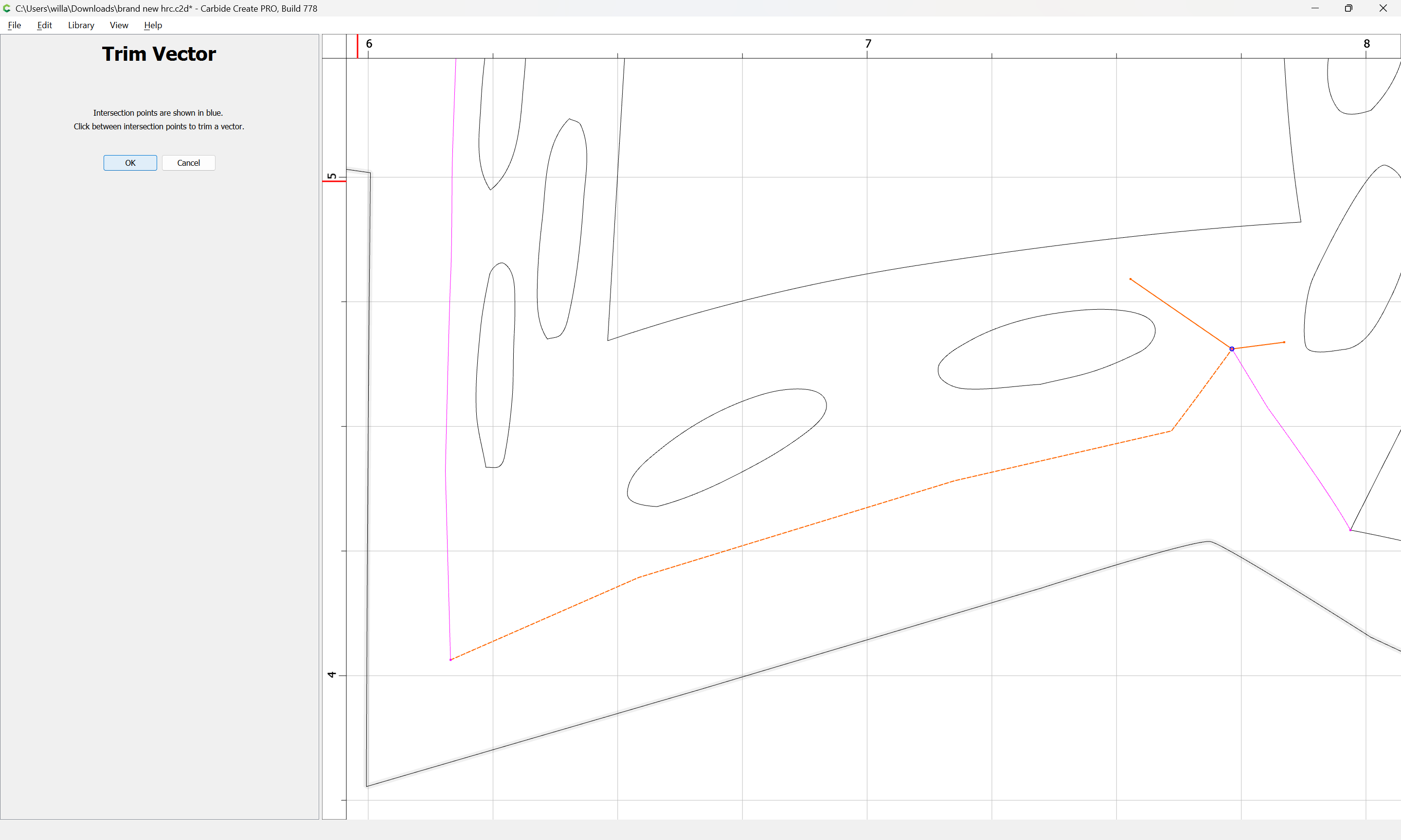
OK
Deselect the cut line:
d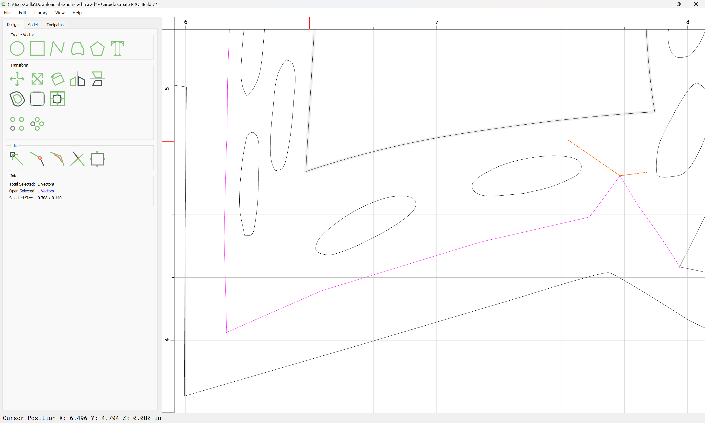
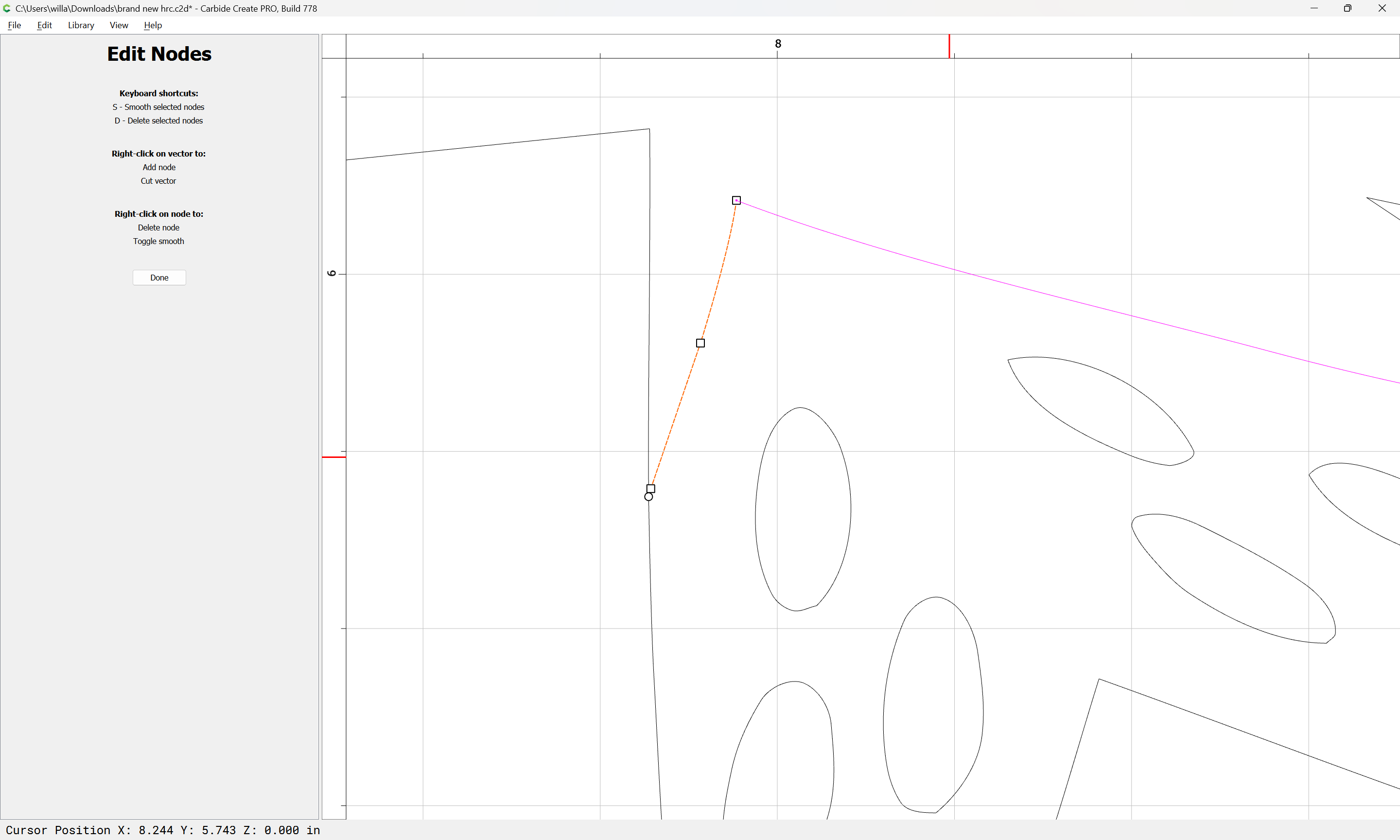
and delete the now superfluous line:
Repeat as needed:
brand new hrc - C3D Version.c2d (212 KB)
Recreating elements and using the Trim Tool along with the Node Editor is a fast way to get to the file I have posted here. I’ll upload the video to IG for you to see.
Done
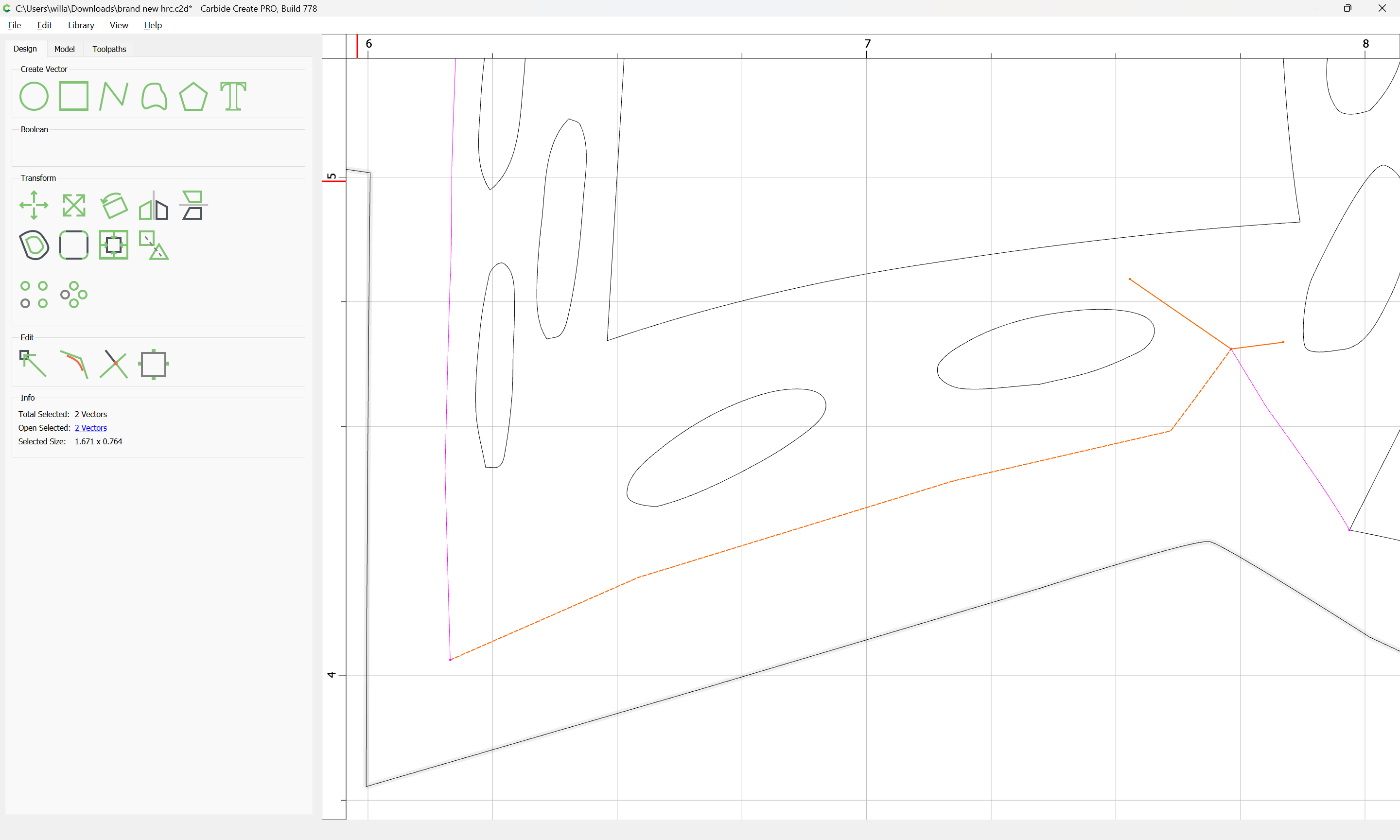
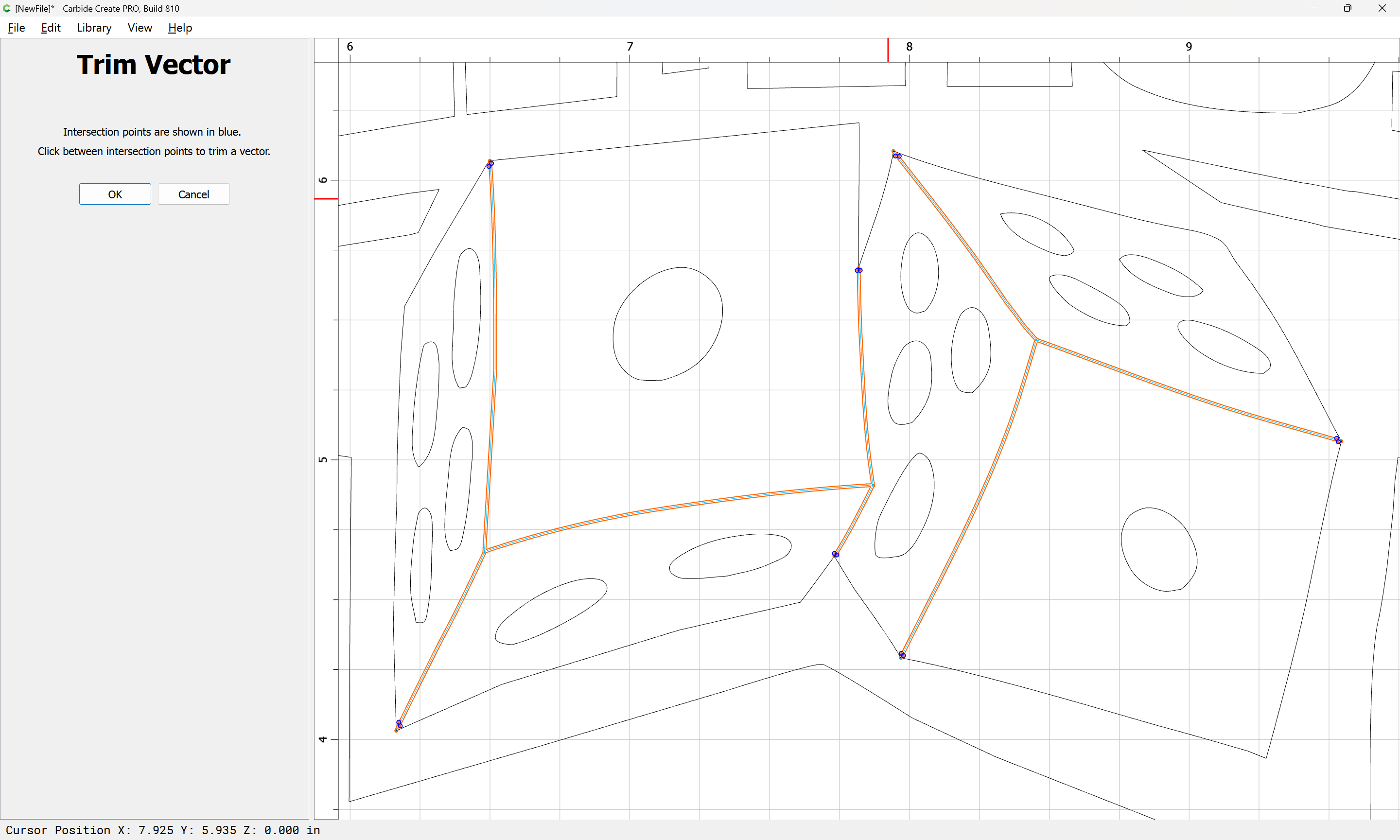
Select:
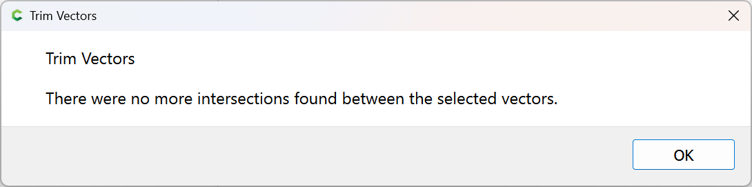
Trim Vectors:
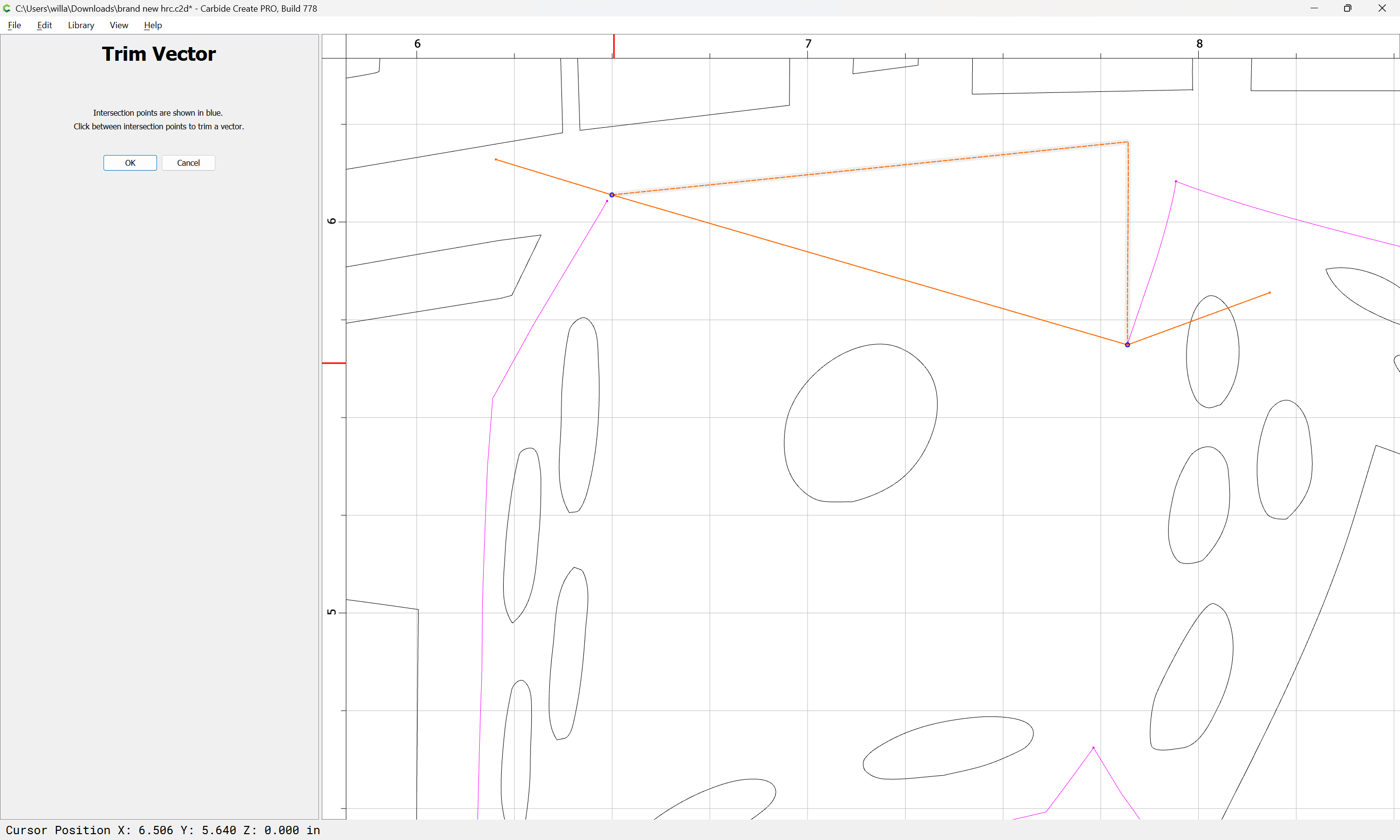
OK
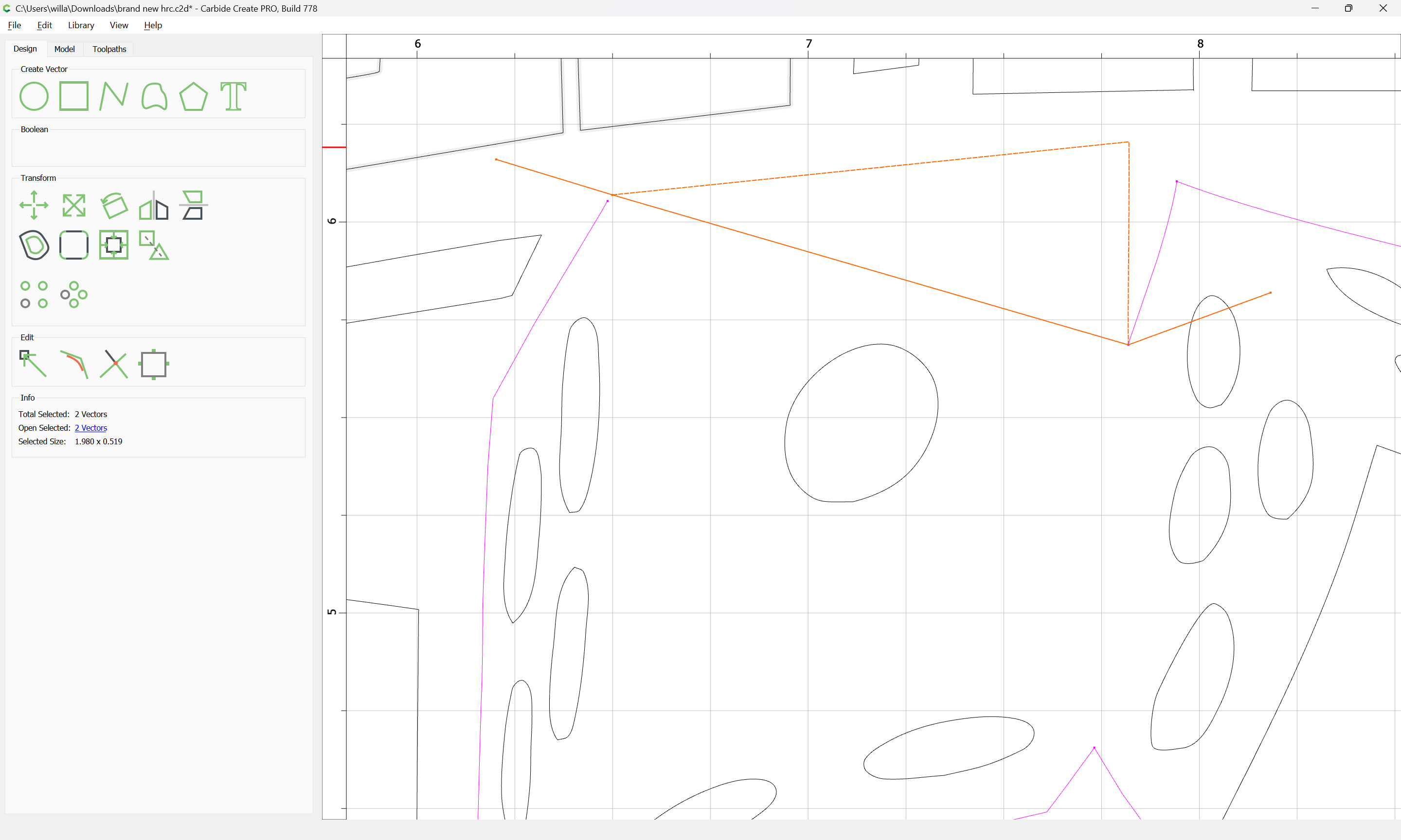
deselect what is needed:
delete what is not:
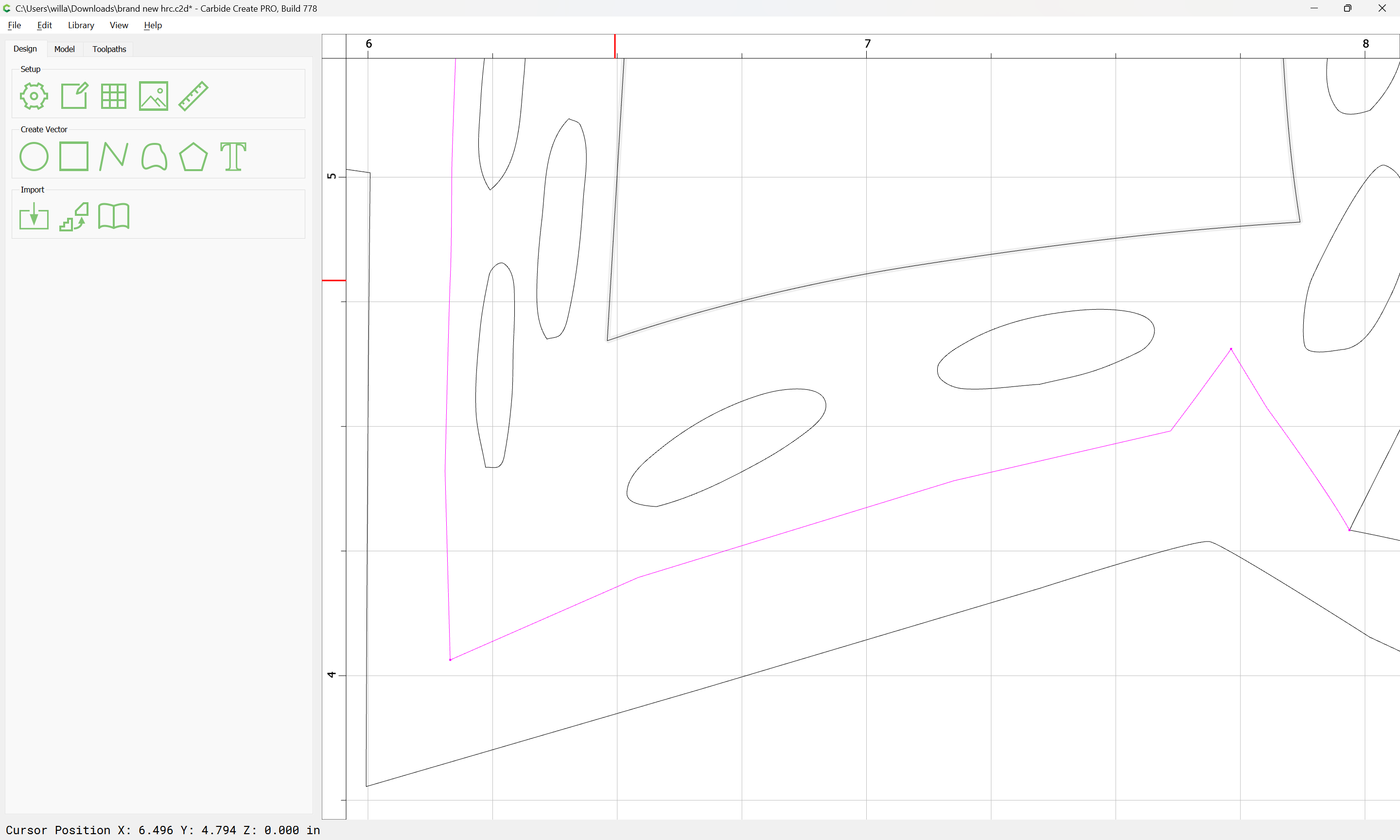
Repeat as needed:
Done
add to the selection:
Trim Vectors:
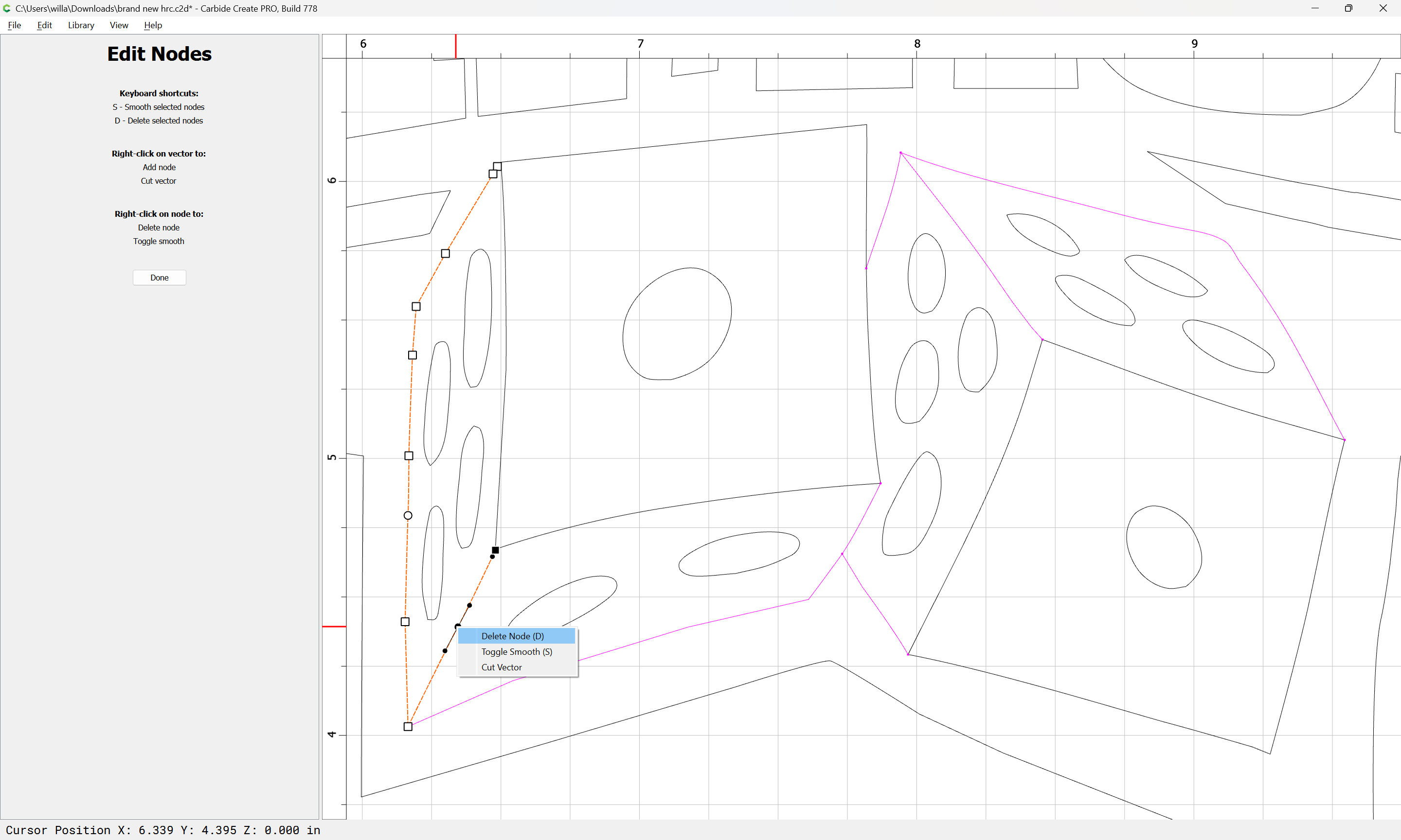
Or, if a line length can’t be cut, use Node Editing:
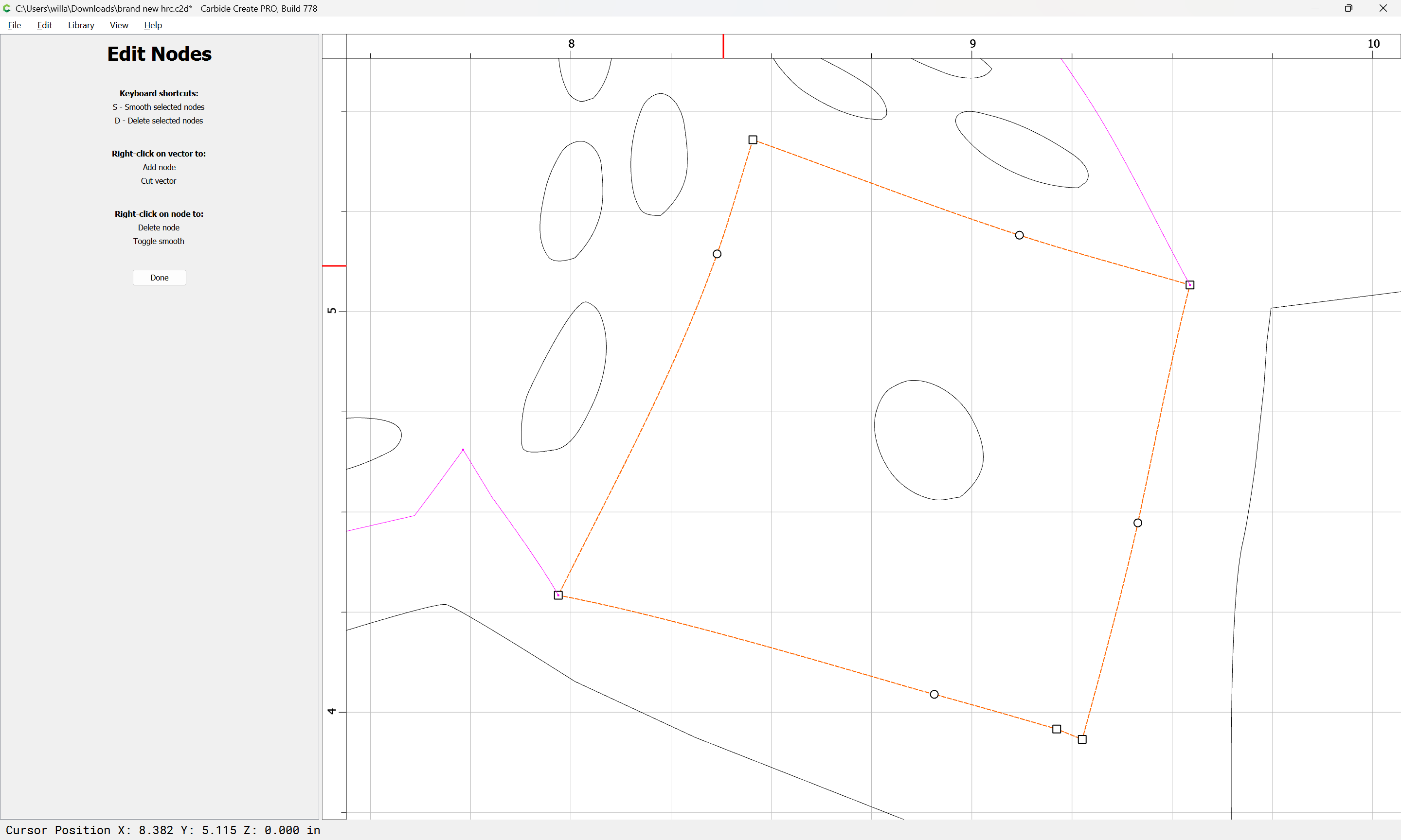
delete
Done
Deselect:
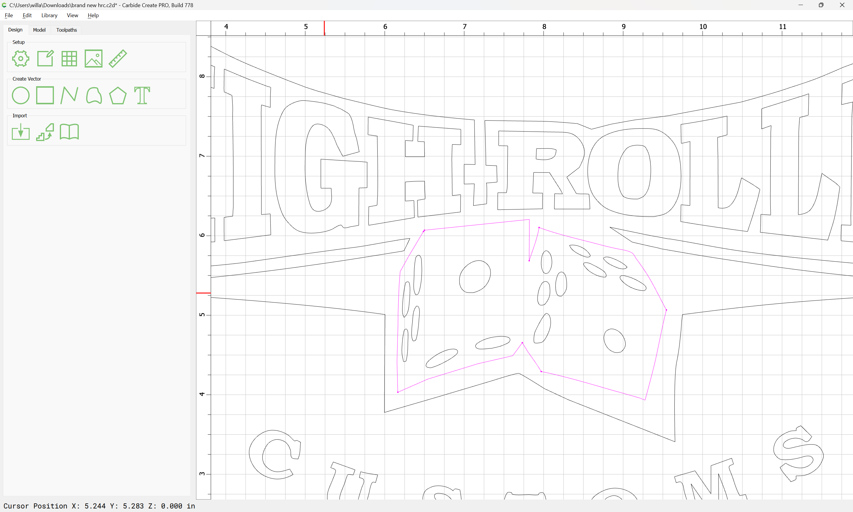
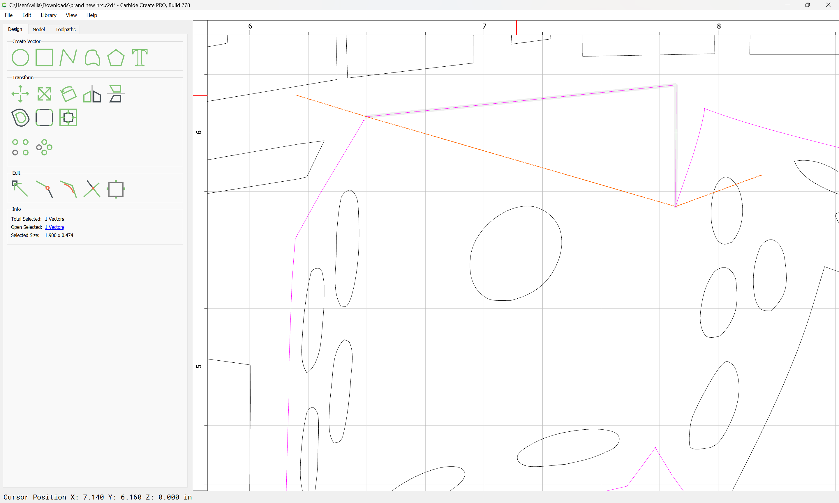
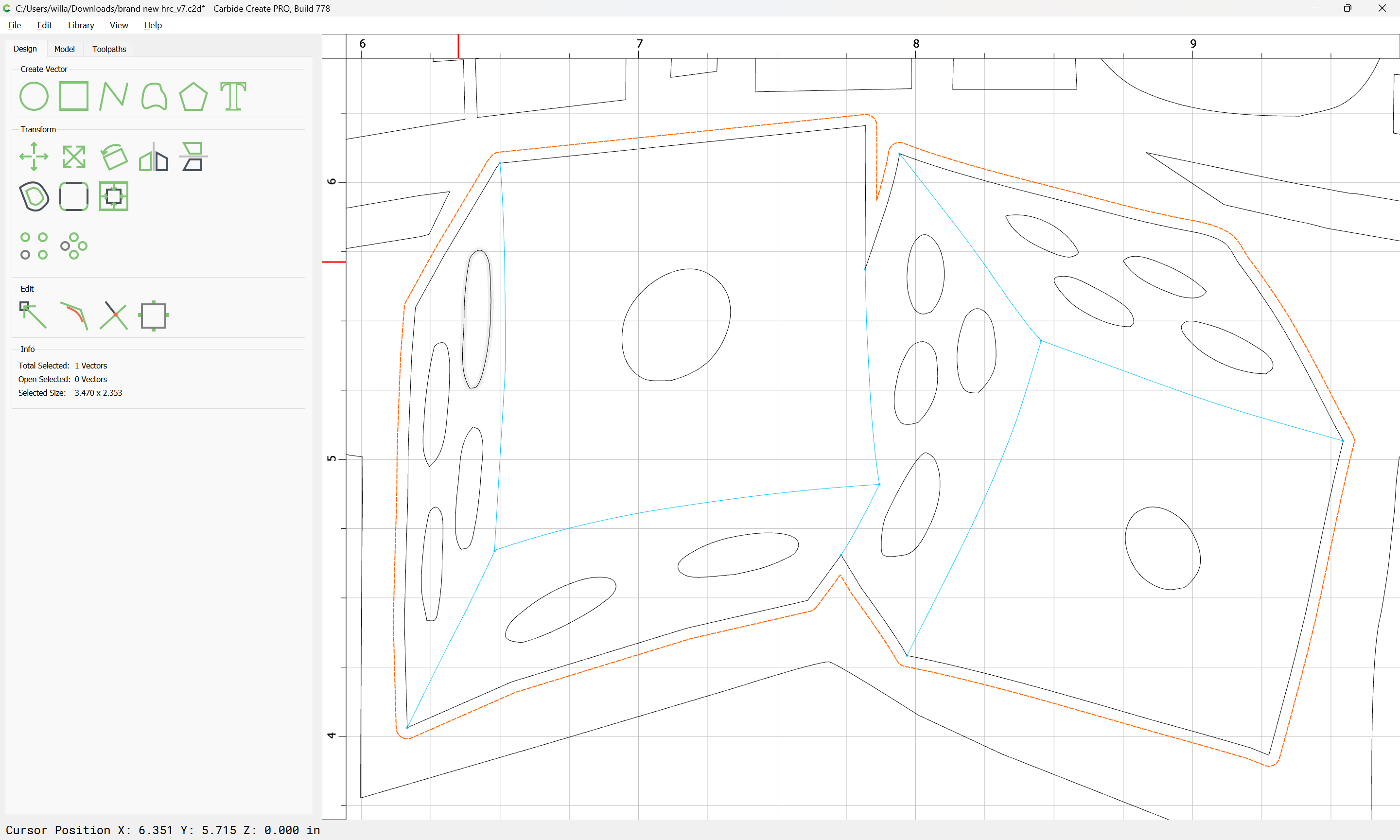
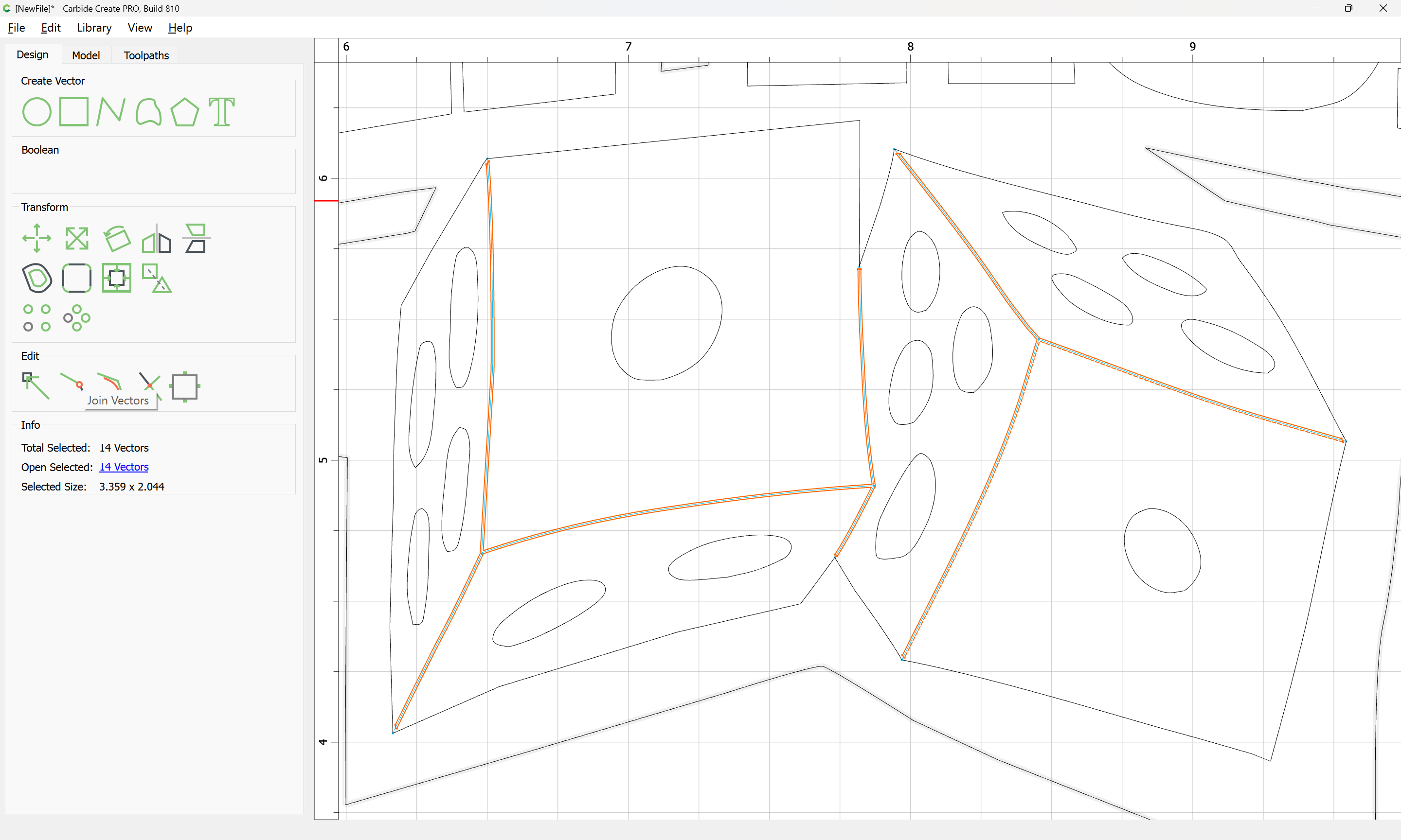
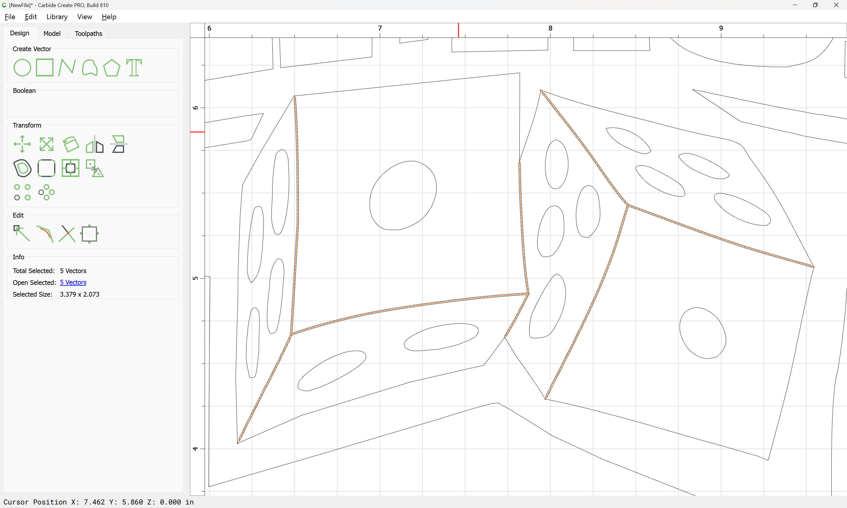
With the region which one wishes to close now described by open geometry, select it:
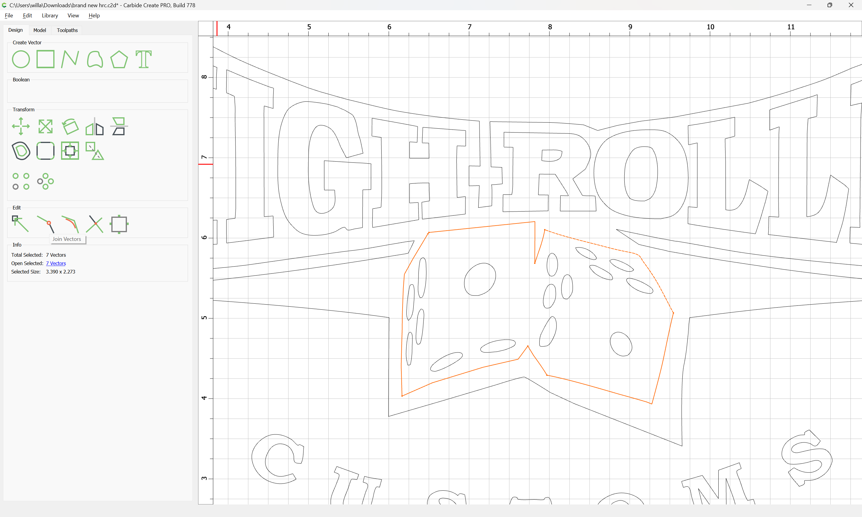
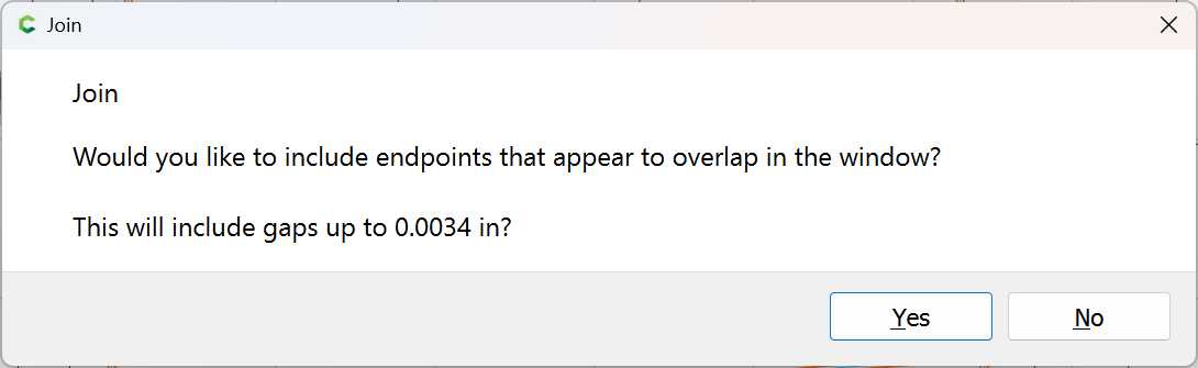
and use Join Vectors to close:
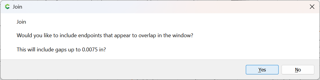
Yes
If the region is still not closed, use Join Vectors again:
Repeat this for the interior geometry — doing so is left as an exercise for the reader — just work from the geometry on the Reference layer.
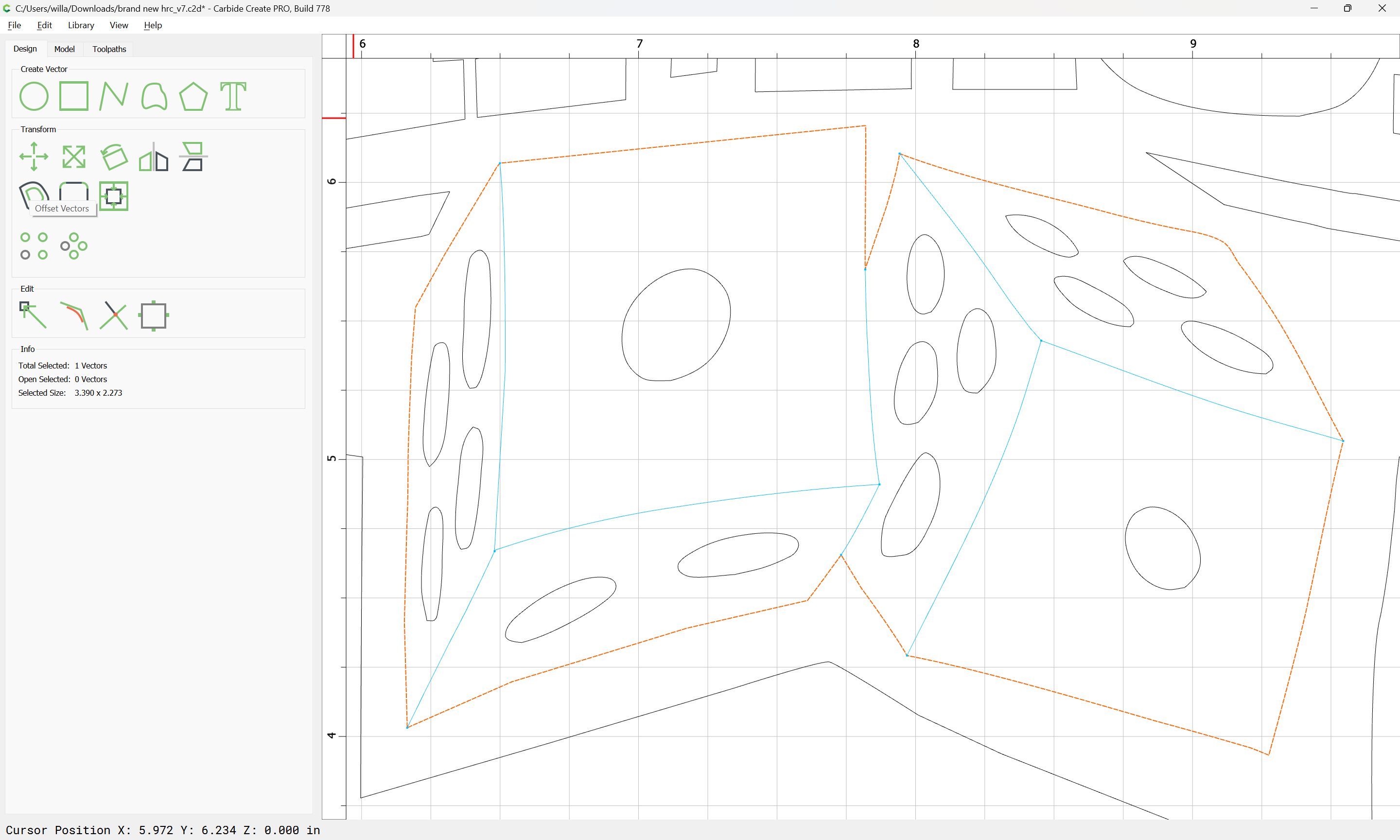
Attached as a v7 file:
brand new hrc_v7.c2d (216 KB)
A simple method for creating closed vectors that look identical to your original design:
brand new hrc - C3D Version.c2d (212 KB)
Note that this is a classic example of the “Figure–ground reversal” problem.
Please see:
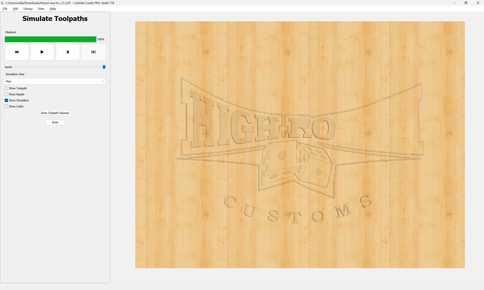
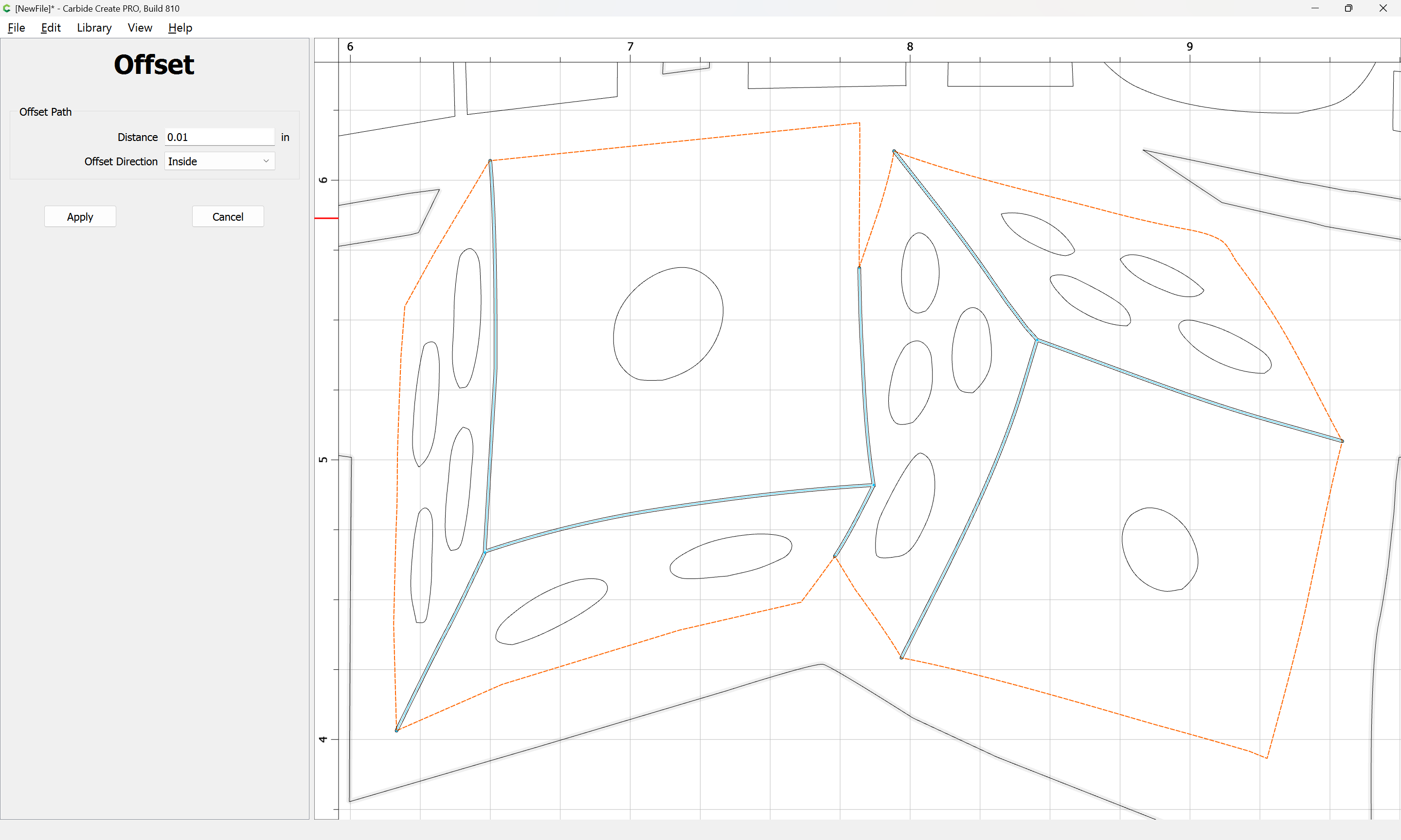
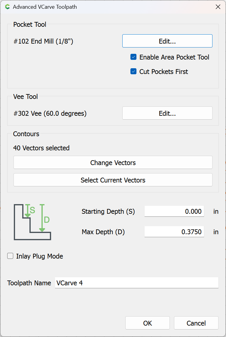
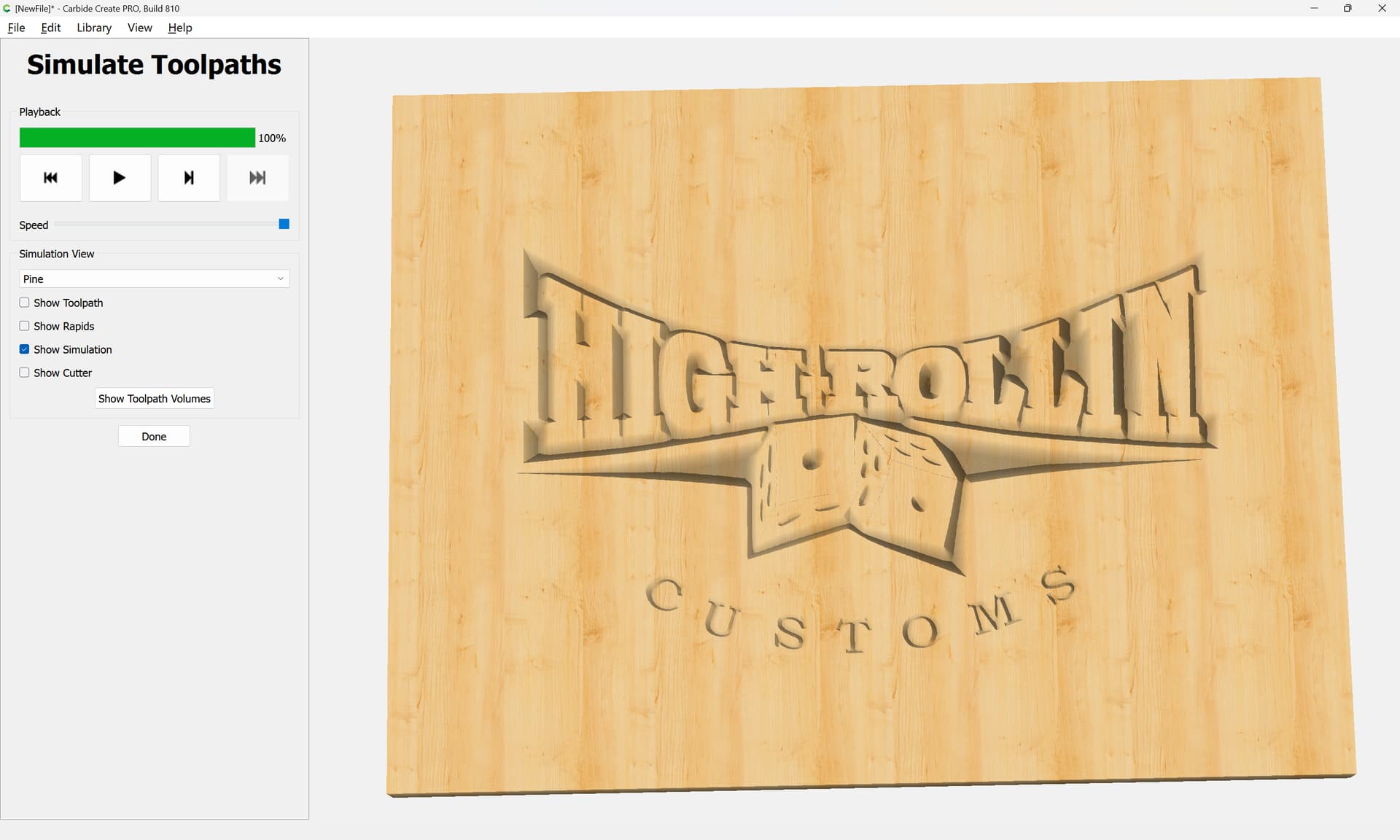
Probably the most expedient thing to do would be to offset the closed geometry and V carve that, then use a No Offset Contour for the interior lines, and Advanced V carving for the pips on the dice, something like:

Apply
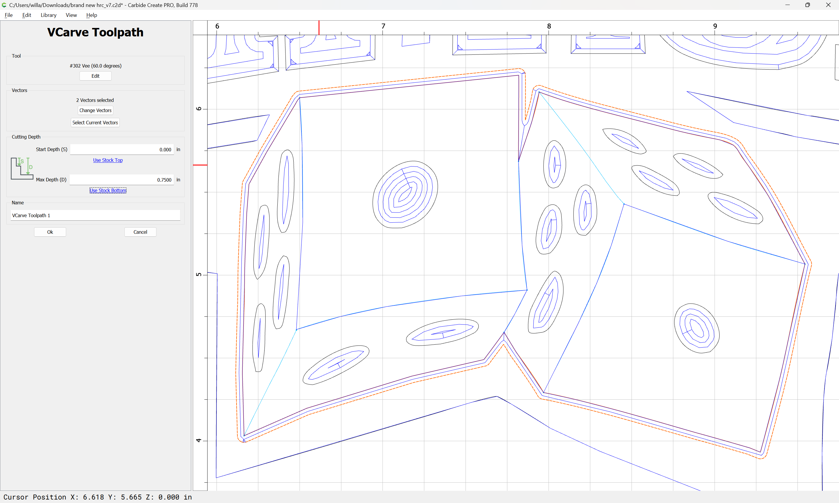
which previews as:
Updated version:
brand new hrc_v7.c2d (228 KB)
Thanks I will try all of that stuff lol. It will take me a little bit. I am new to this
Just keep at it. You’ll get there.
Hey it is the Tumbling Tumbling Dice when Mic Jagger was not coming out on stage on a walker.

Well I can’t figure out how to do the inner lines of the dice. They still are blue. Don’t know how to tie them together. Spent all night trying to figure it out. Don’t know why you can’t just edit the nodes and put them all together.
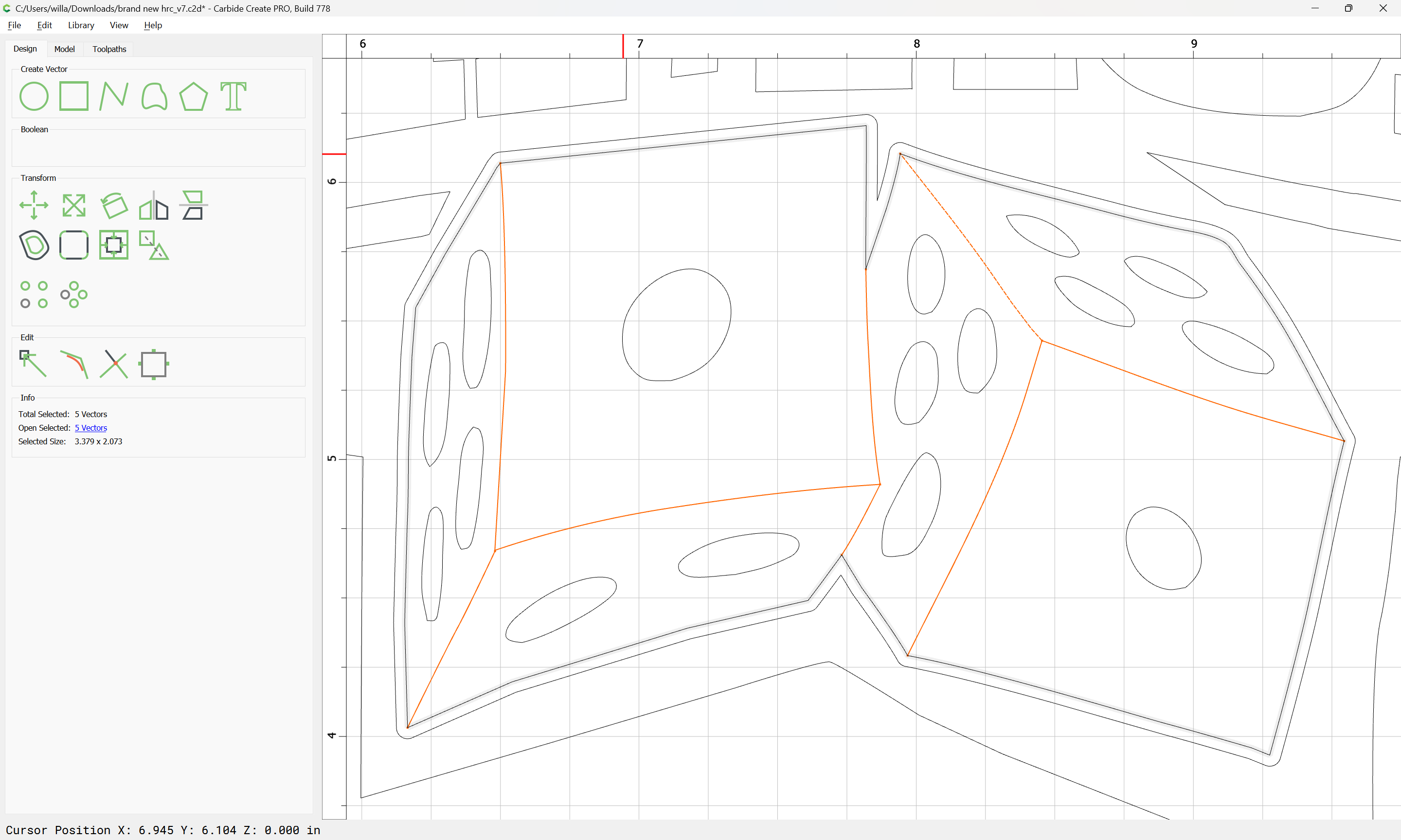
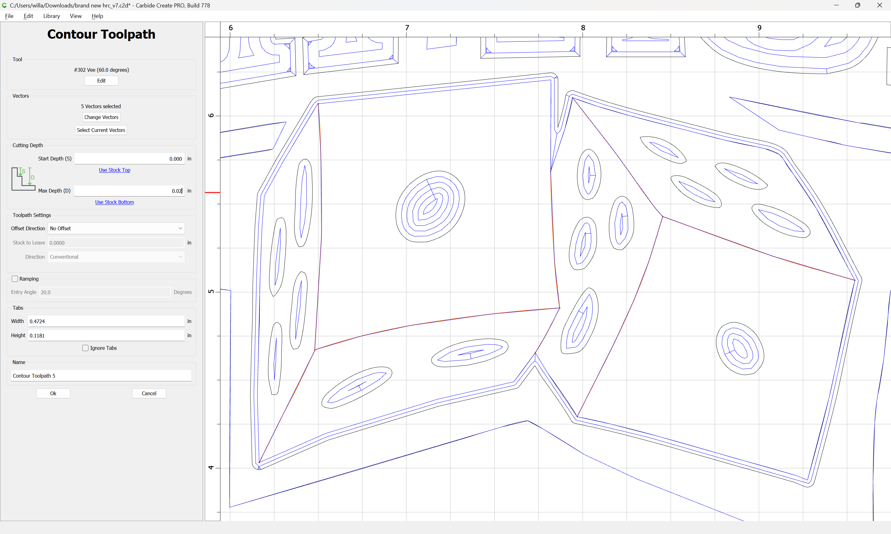
The inner lines don’t need to be closed — as I showed in my file they can be represented using open geometry and No Offset Contour toolpaths.
The possible representations here are:
- separate closed regions for each face of each die
- a surrounding closed region which describes the entire area of both dice — that then leaves the lines which describe the separate faces — those may be shown either as:
- open geometry as is shown above
- small interior closed geometry
As to why six separate regions can’t be described as a single closed region, well, that’s basic geometry:
See Euclid’s Elements: Book I definitions 13 and 14:
https://mathcs.clarku.edu/~djoyce/java/elements/bookI/defI13.html
and read up on topology.
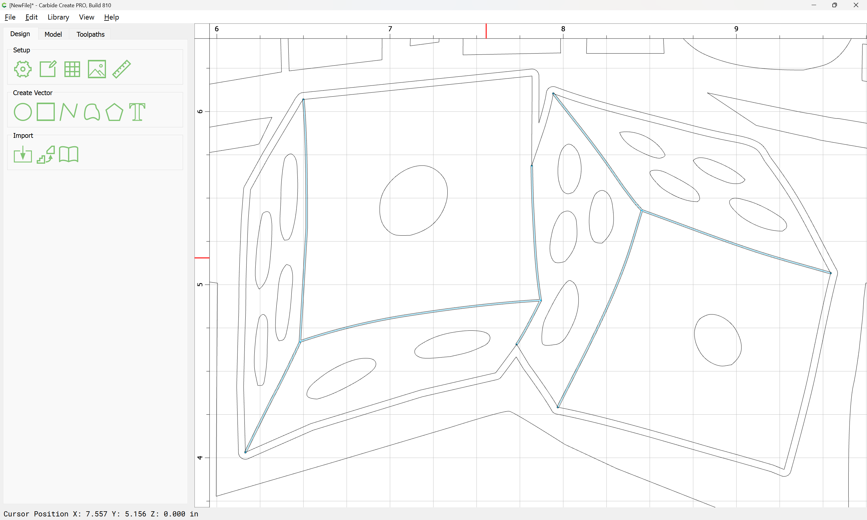
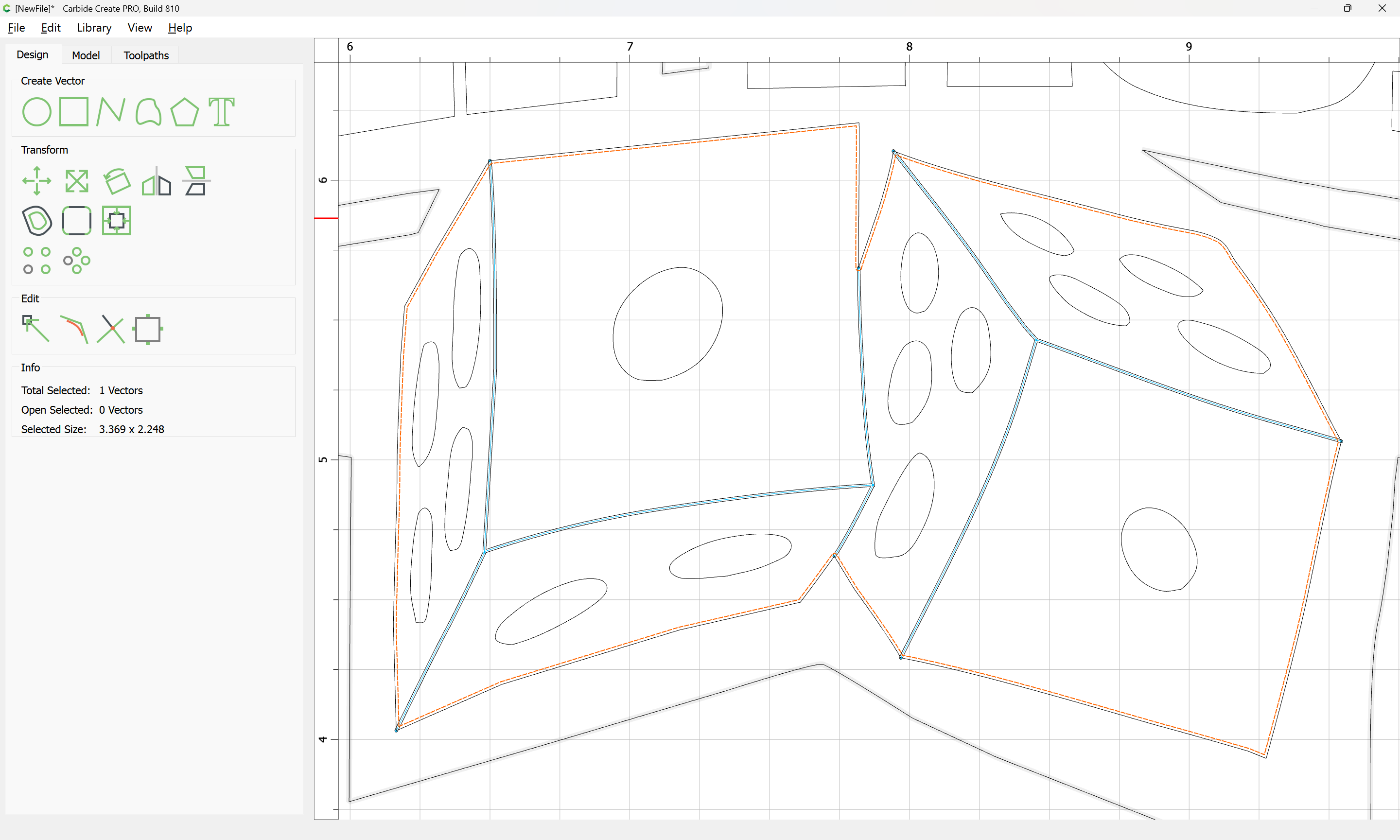
If one wishes, the open geometry:
may be inset/offset and then closed. Easiest way to do that is to export to a drawing program:
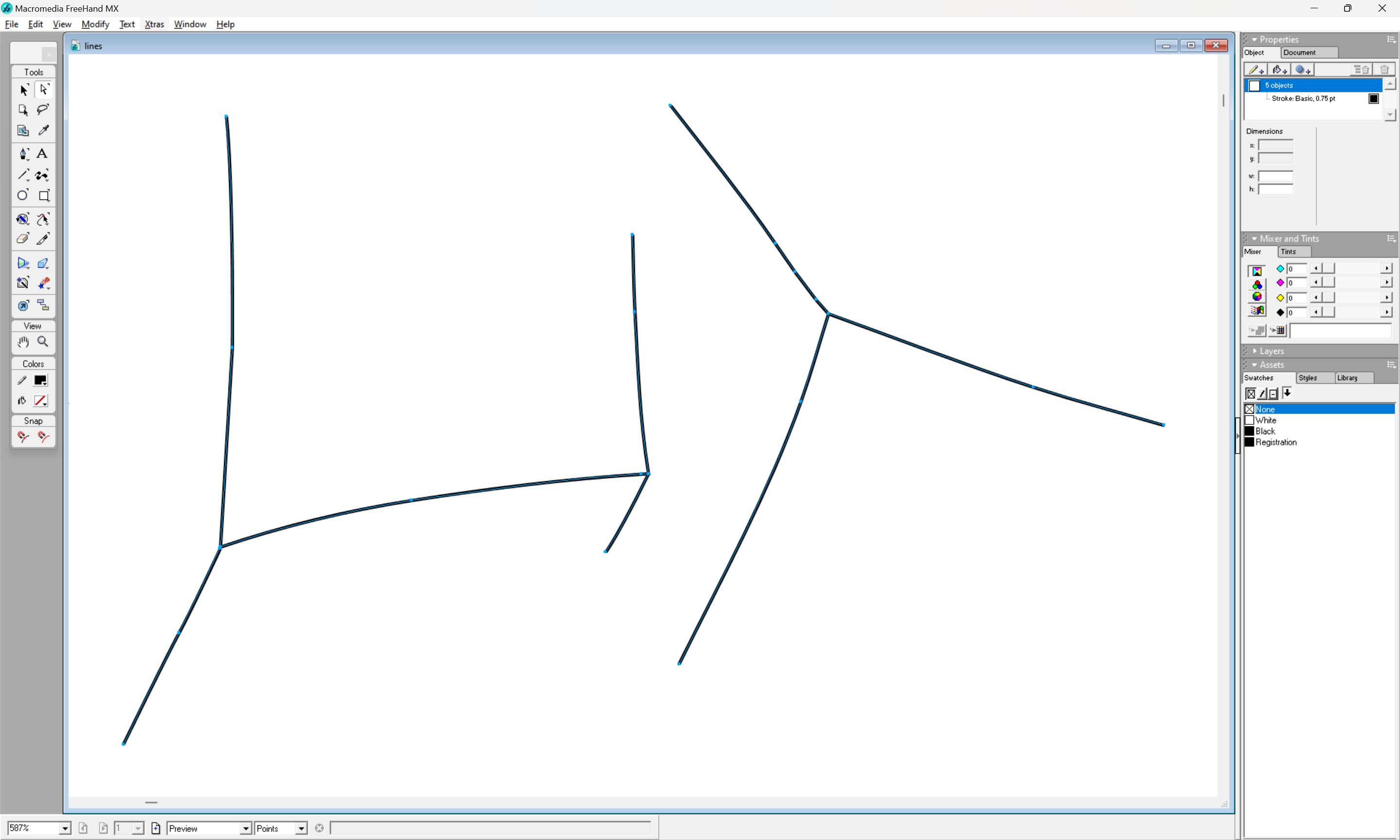
and then instantiate the outlined stroke as a closed path:
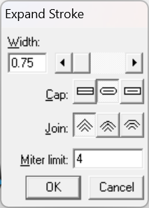
which may then be imported into Carbide Create:
The offset geometry deleted:

The outline geometry inset slightly:
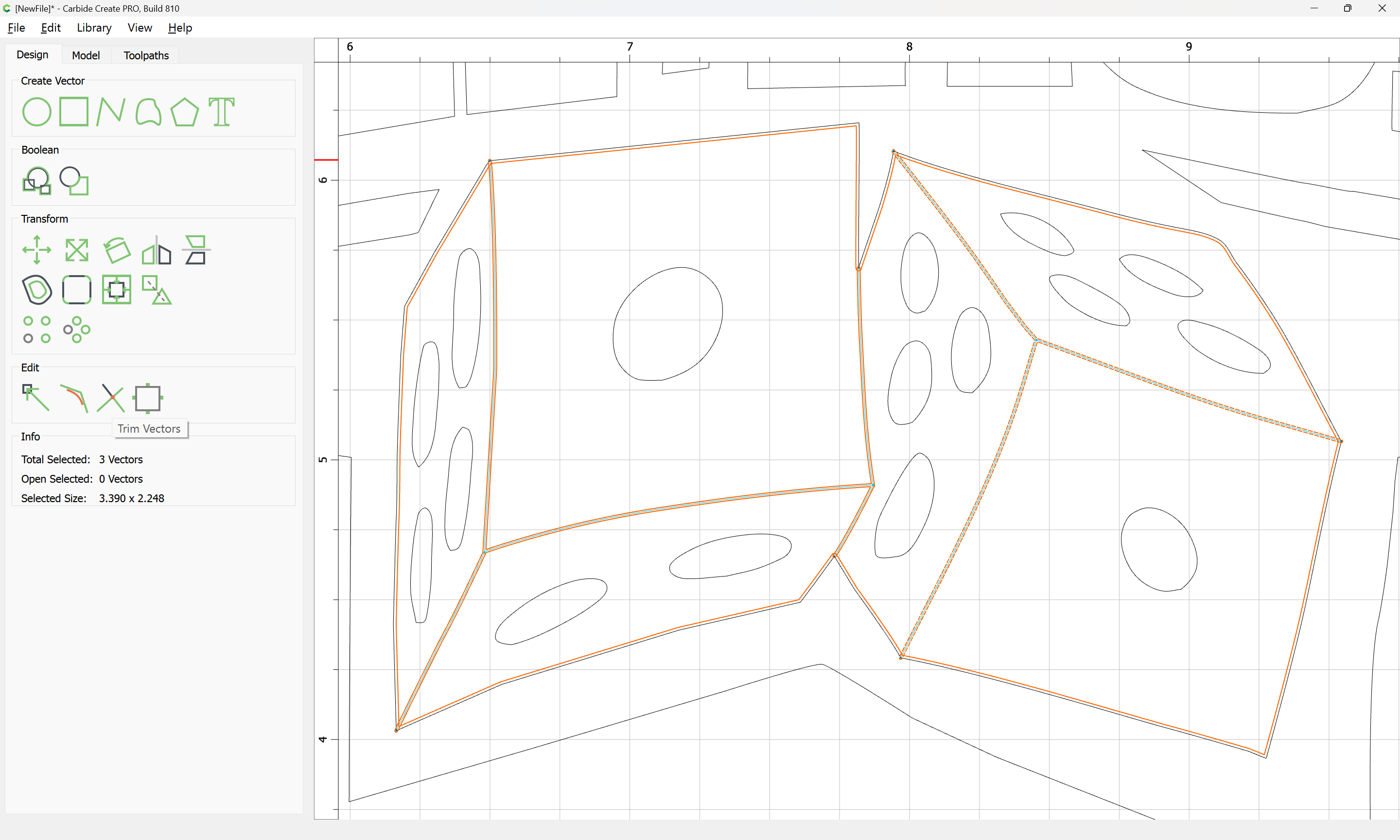
Then Trim Vectors used to reduce down to a set of lines which describe a closed region:
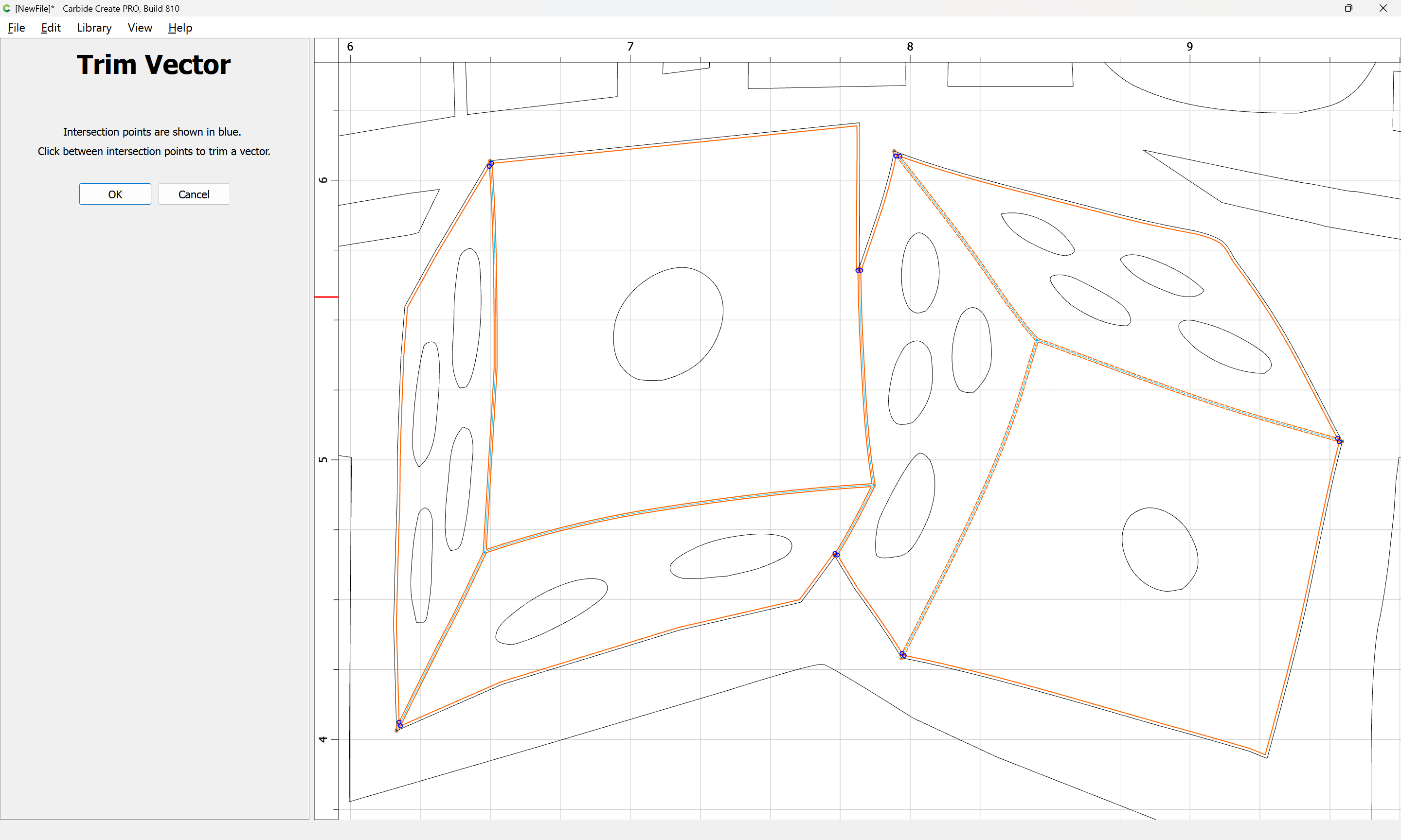
Zooming in/out as is needed:
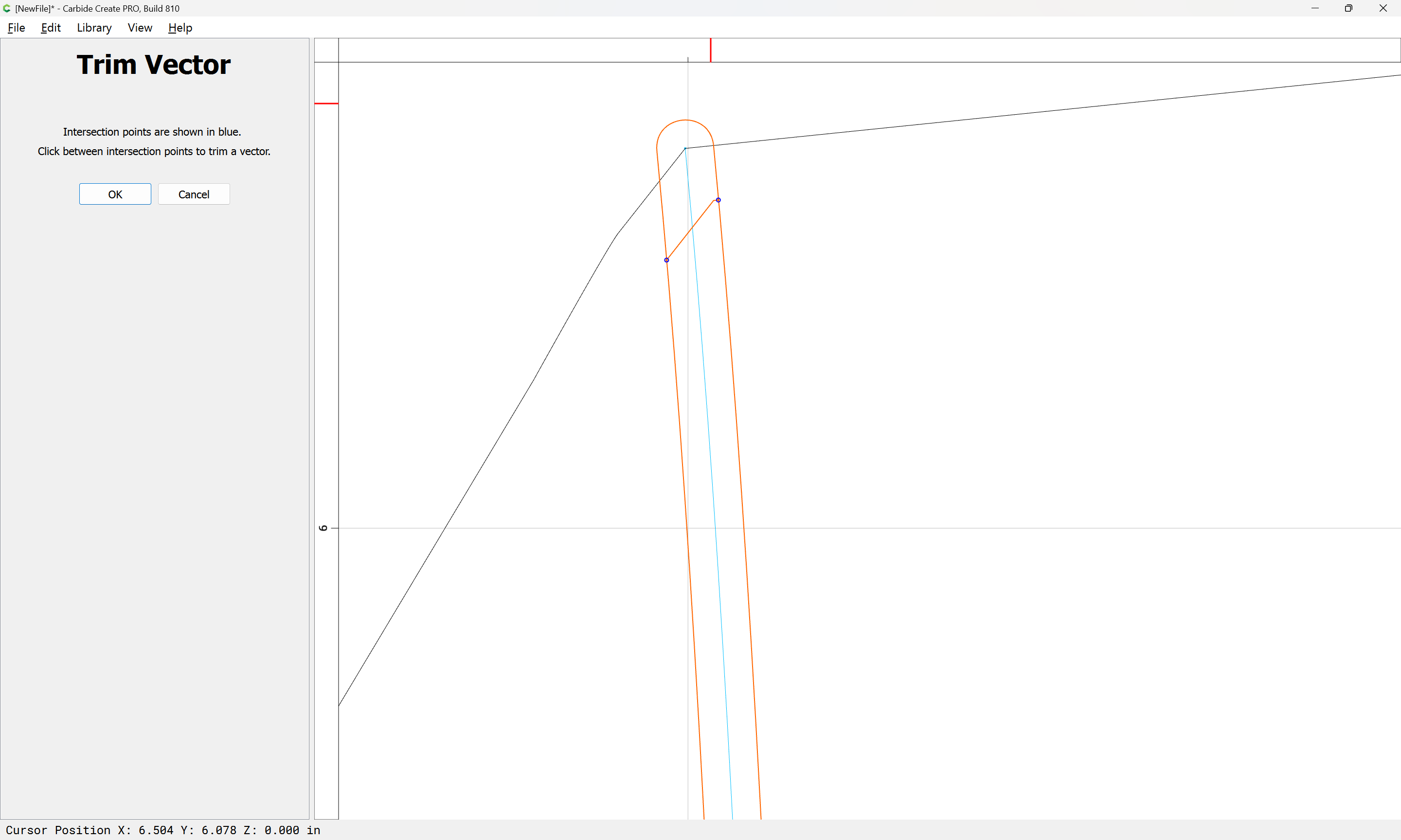
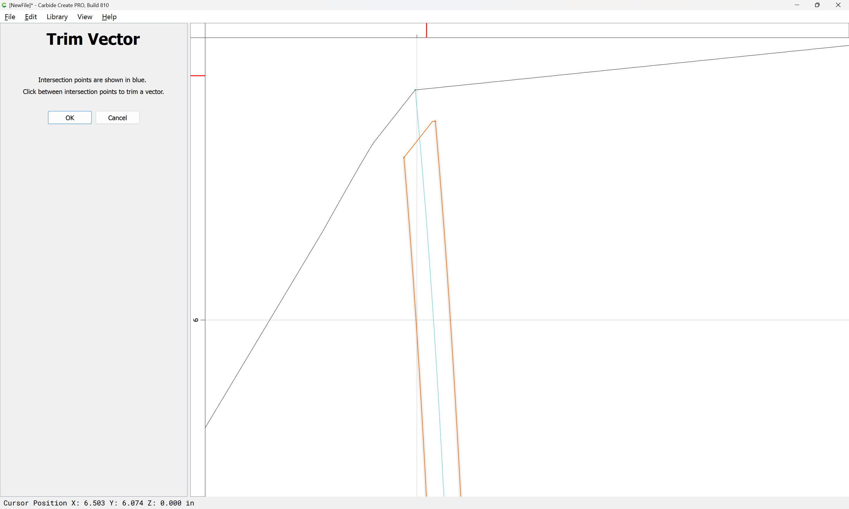
until one arrives at:
OK

OK
and then closed using Join Vectors:
Yes
Then the open vectors may be selected and deleted:
and if desired, a toolpath which requires closed geometry applied to everything:
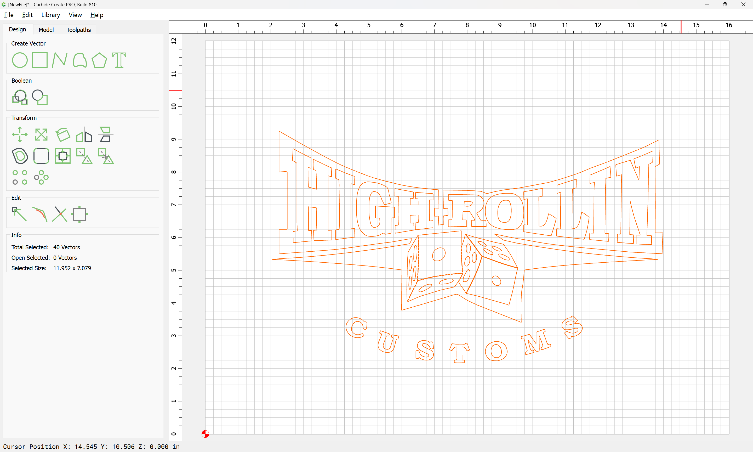
Attached as a v8 file.
brand new hrc_v8.c2d (208 KB)
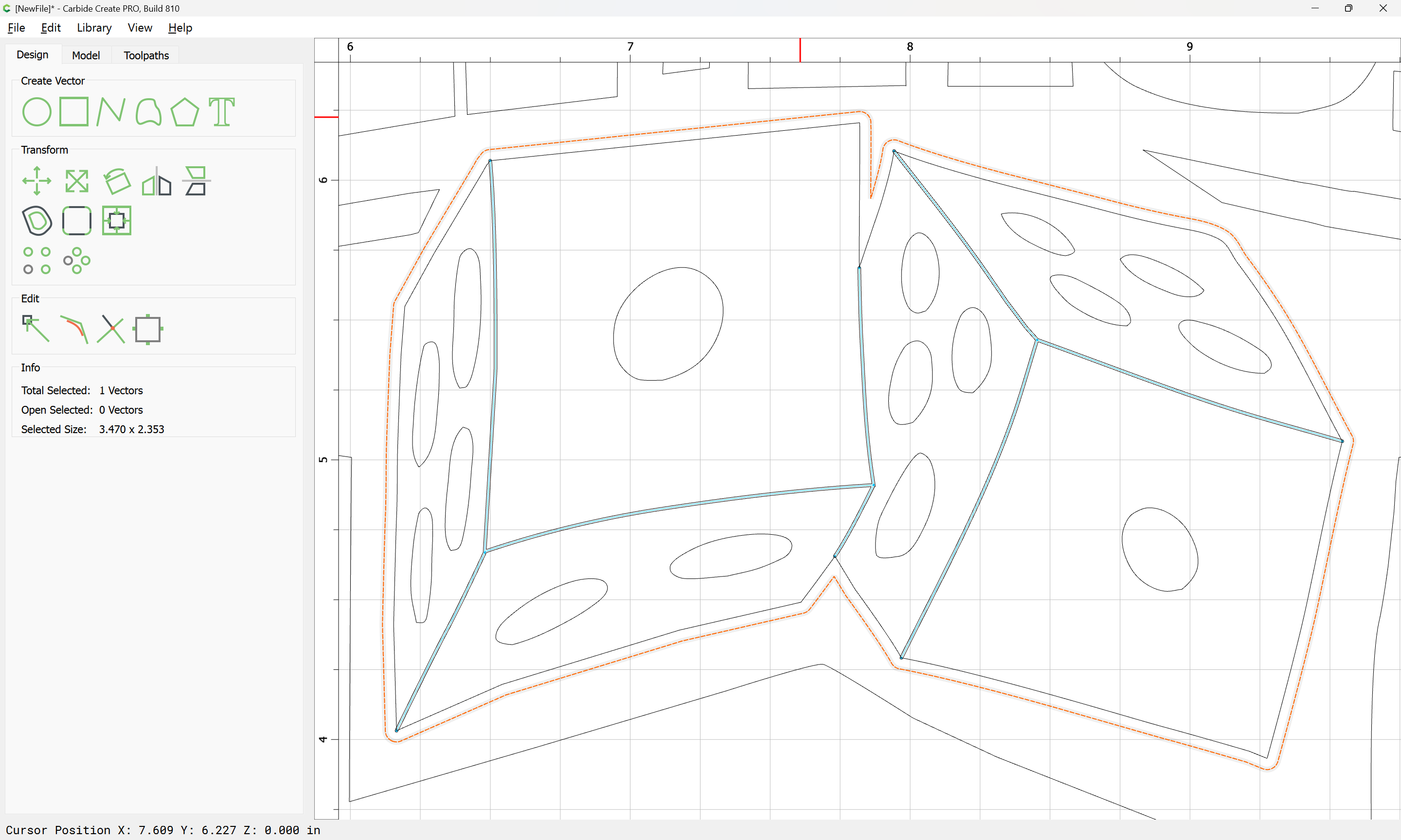
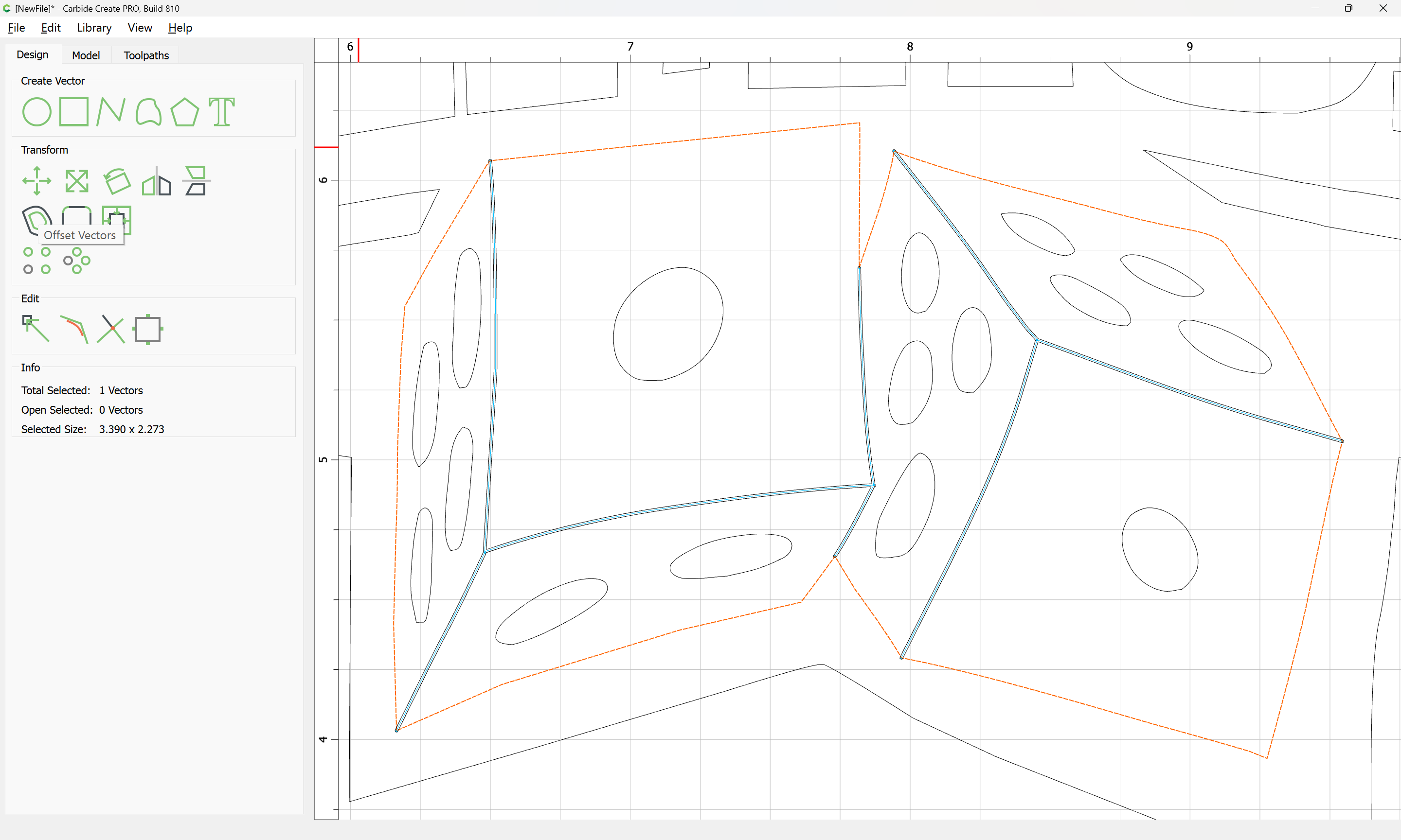
Alternately, if the original file had had 6 closed regions, one for each visible face it would have been possible to select non-adjacent sets:
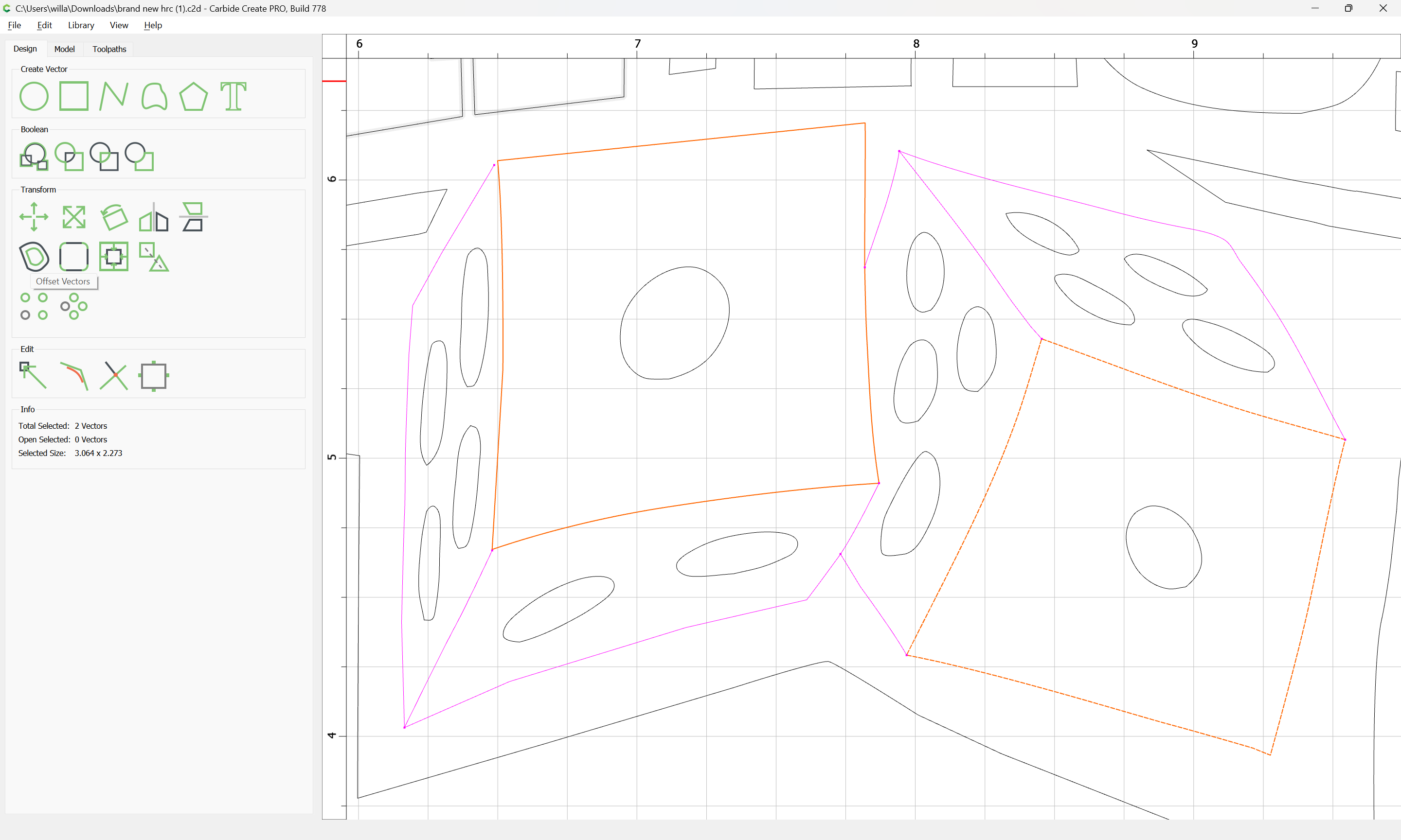
and use Offset Vectors:
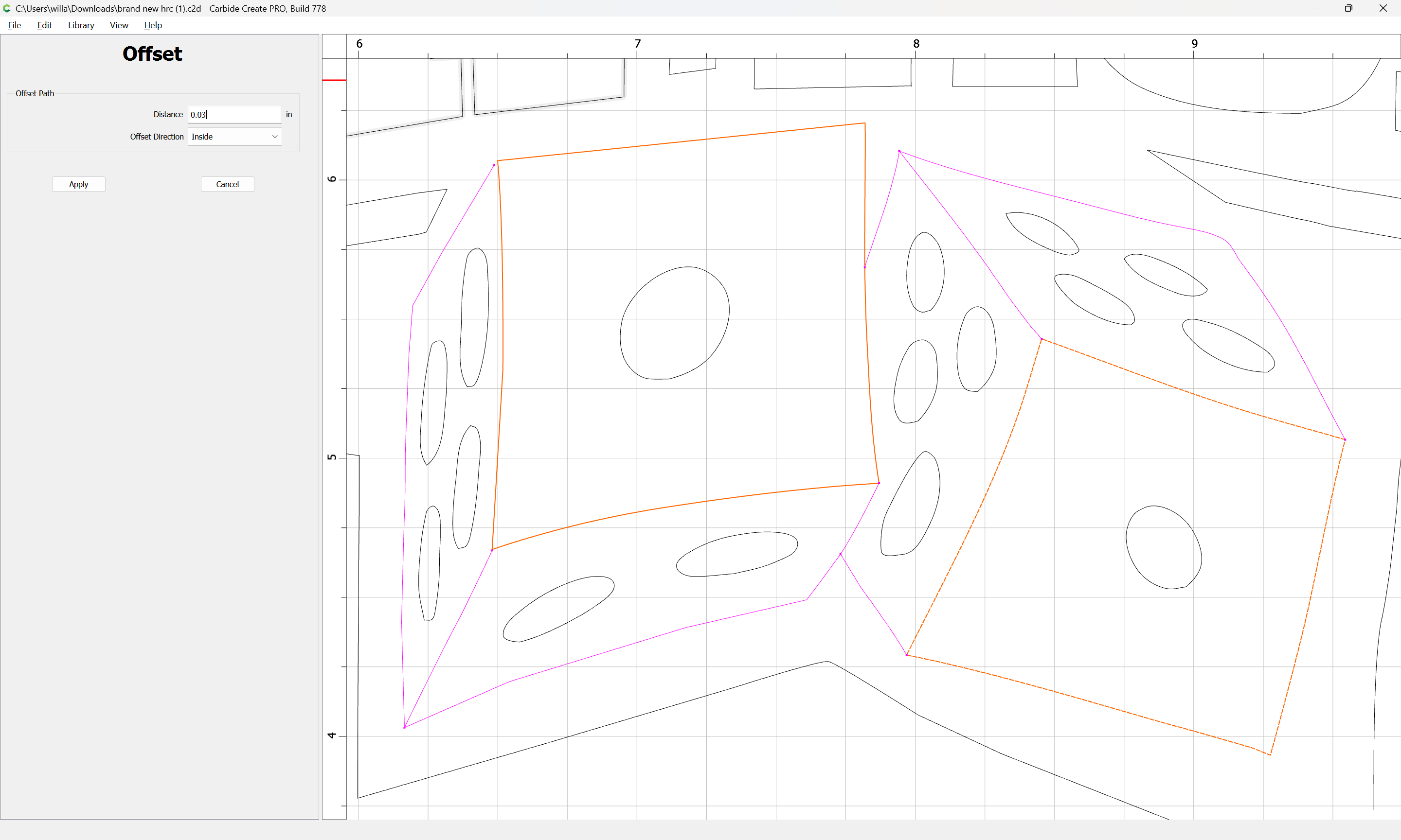
to inset each:
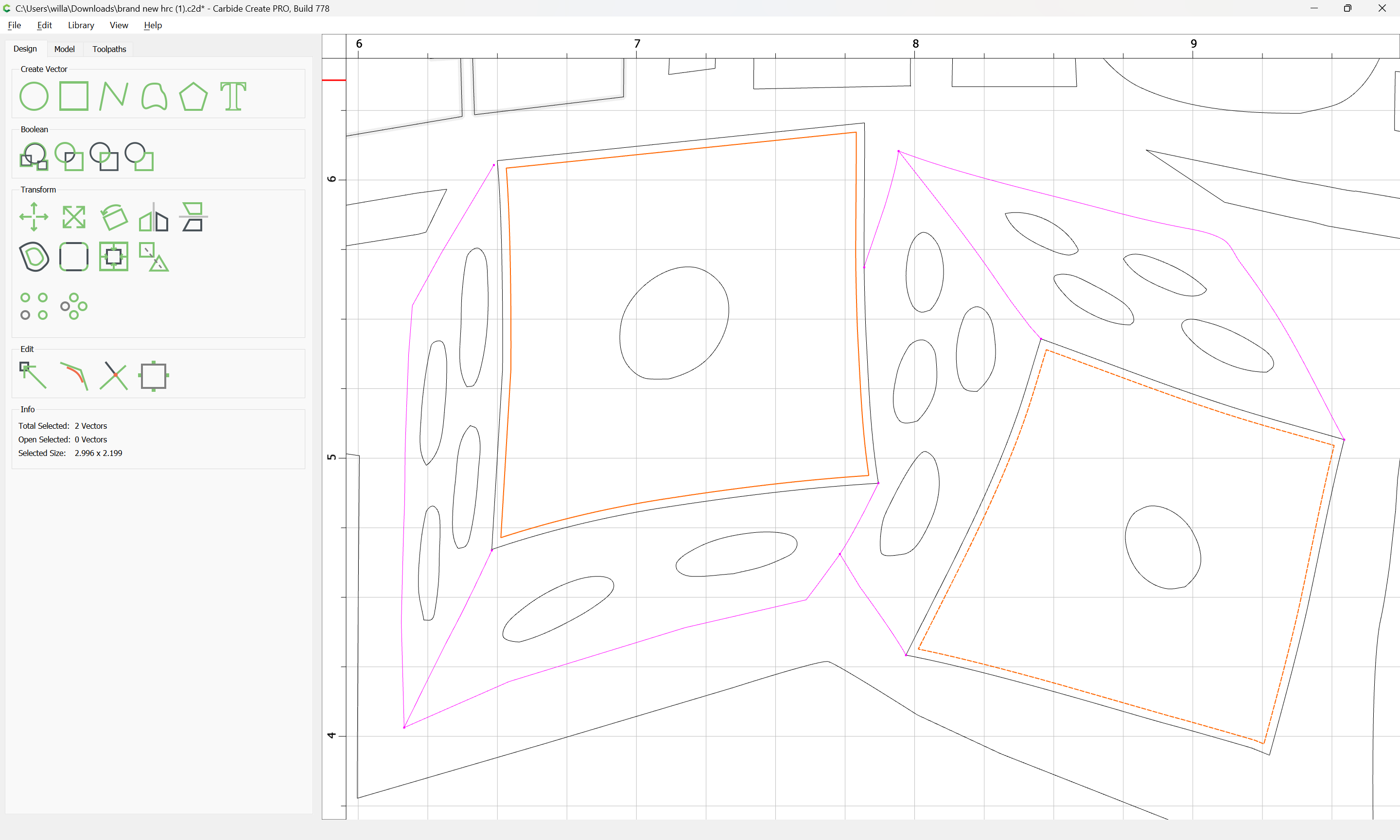
So as to arrive at a set of six separate closed regions which might be workable.
What you’re trying to accomplish here is quite challenging. Being able to pick apart a 2D Logo and turn it into a 3D object seems easy, but is actually an advanced skill.
This video may help you with some of the concepts: https://youtu.be/3Ilq93DHV7w