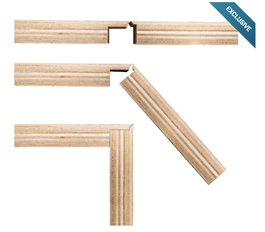
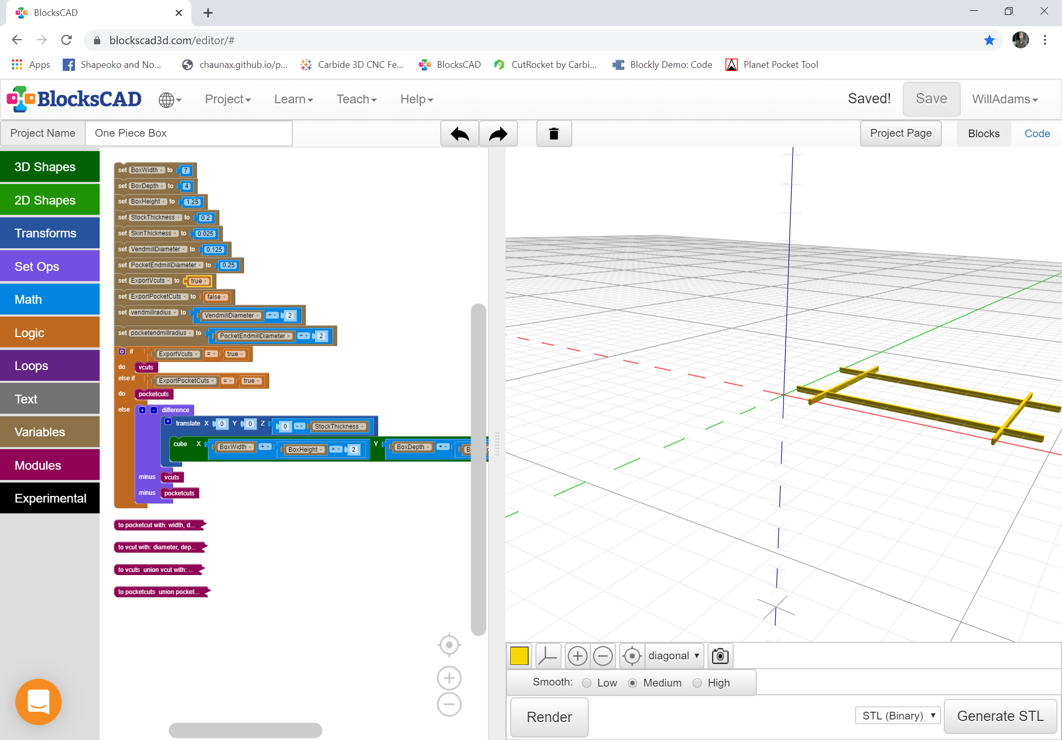
I think this would be a great idea for BlockSCAD/OpenSCAD @WillAdams… Rockler currently sells specialized dado stack that allows you any piece of panel good into a box just by making 4 cuts on your table saw.
This is highly desirable from a production time standpoint as well as being able to achieve continuous grain on the outside of the box on ALL of the sides. However, the parametrics behind making this a “design by numbers” model are beyond my proficiencies in design software at the moment so i thought I would throw this idea out here and see if anyone wanted to take a shot at making it.
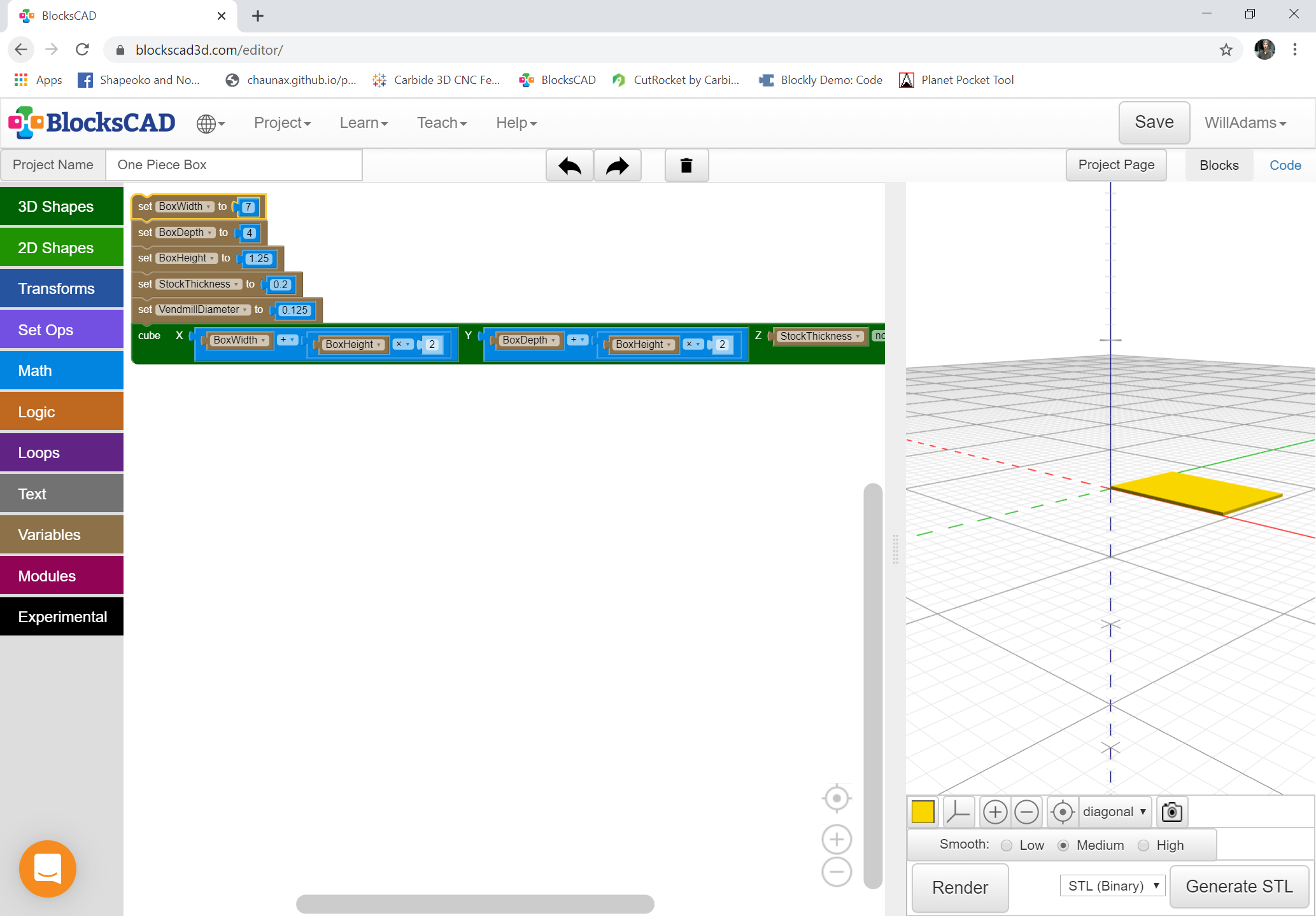
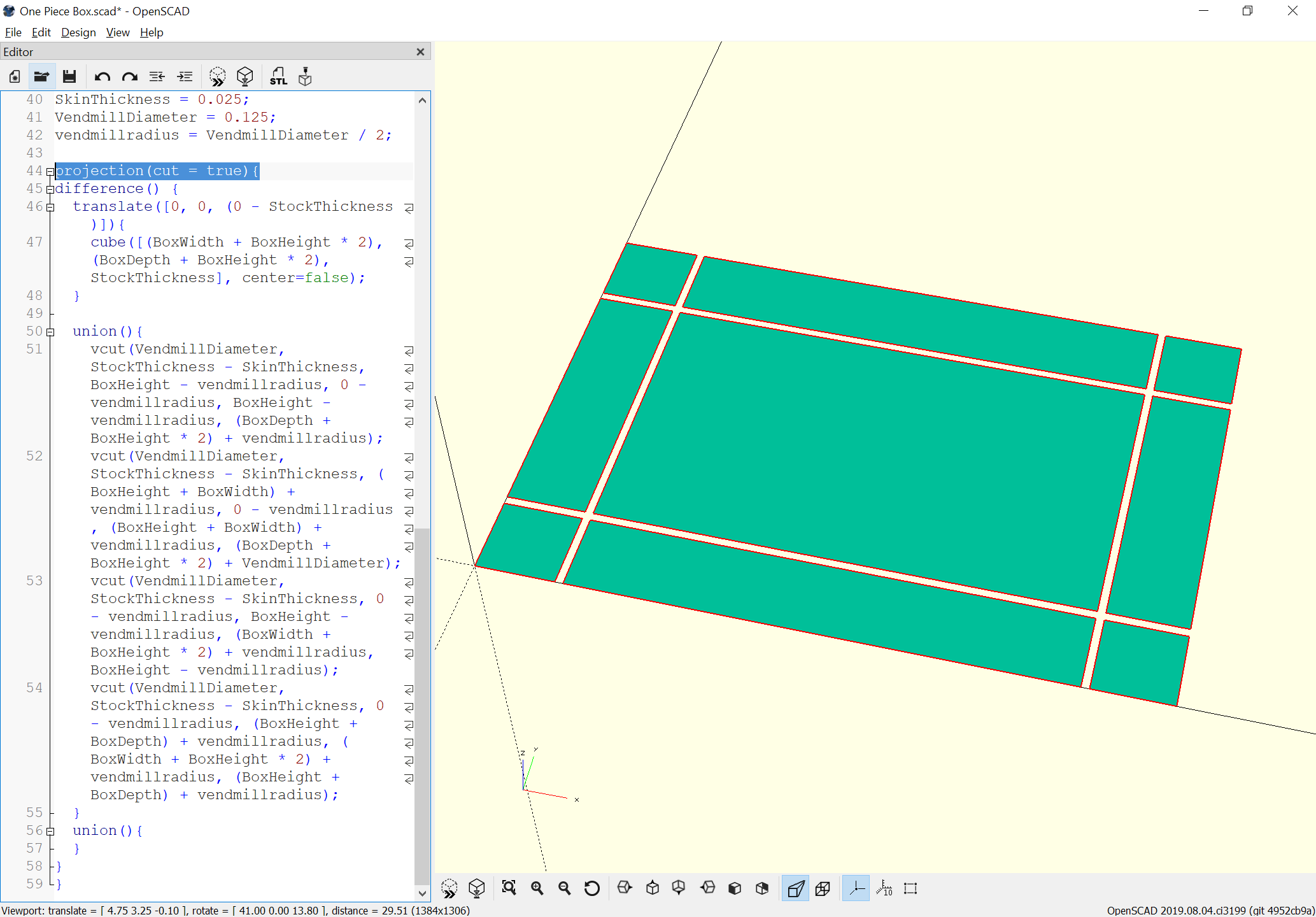
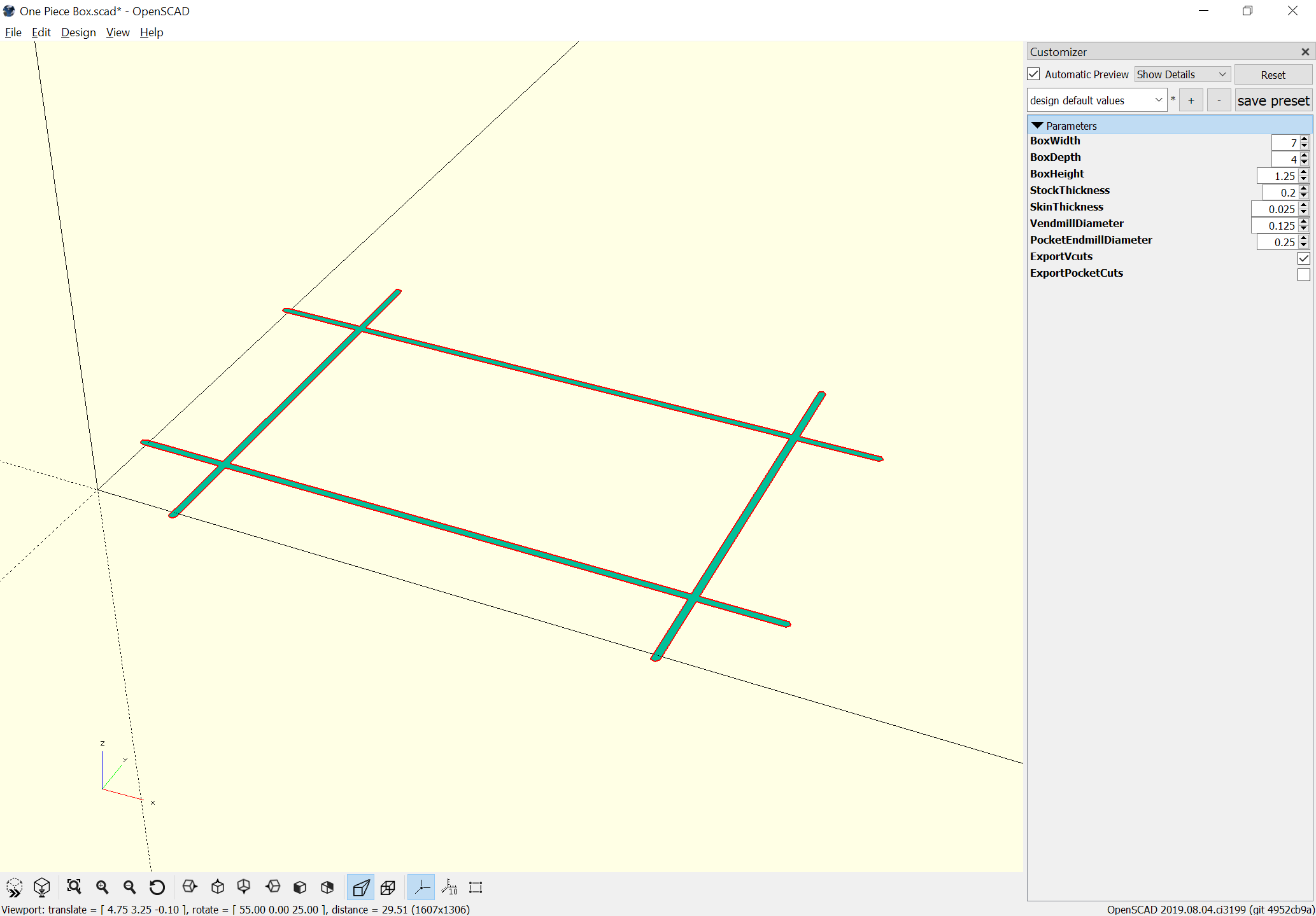
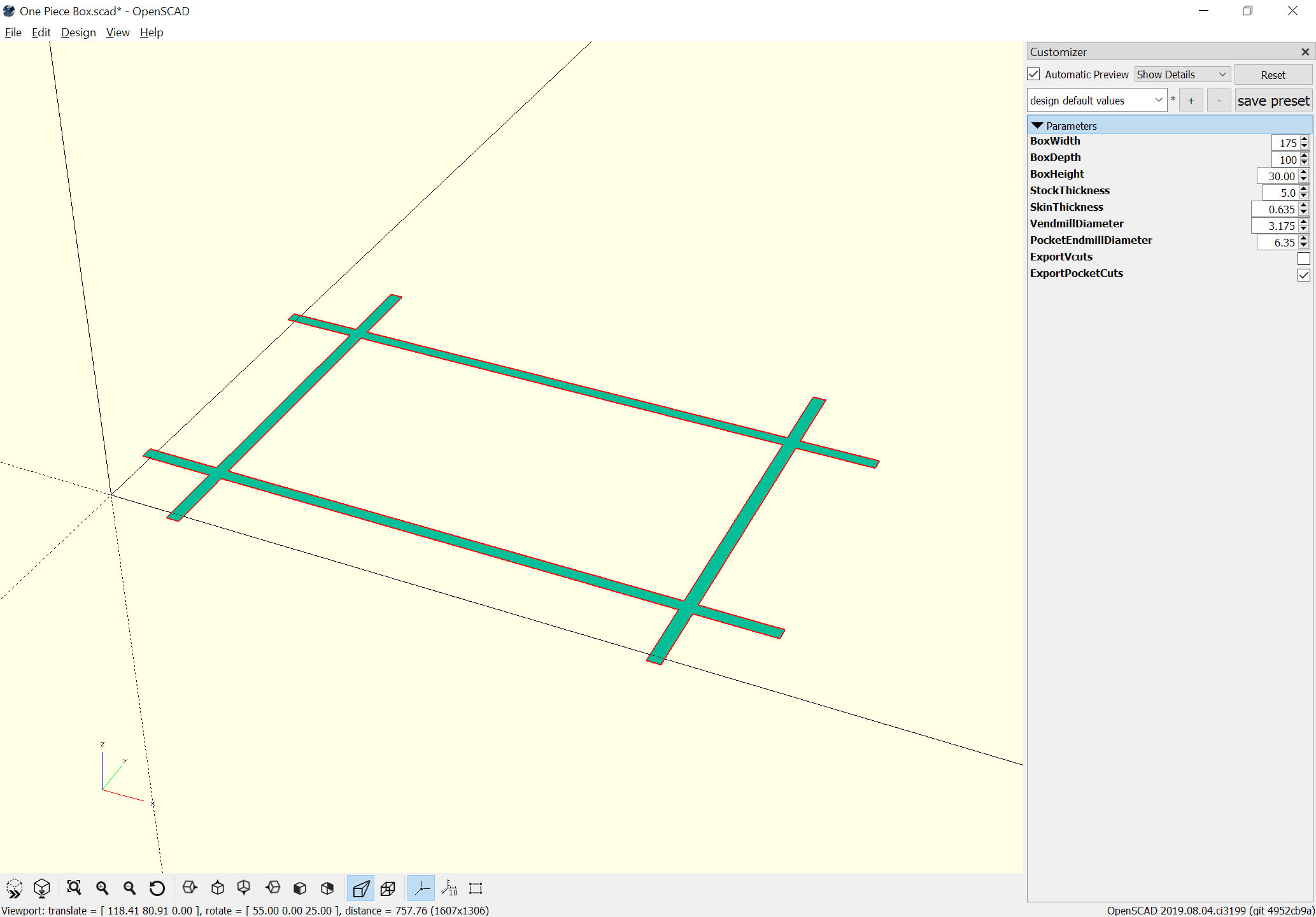
Next we need to model the V endmill and determine how deeply it should cut at and how much material to leave (probably need another variable for that latter dimension — the plywood I’m using has a skin thickness of 0.025in so we’ll roll with that). Offsets are by the radius of the endmill.
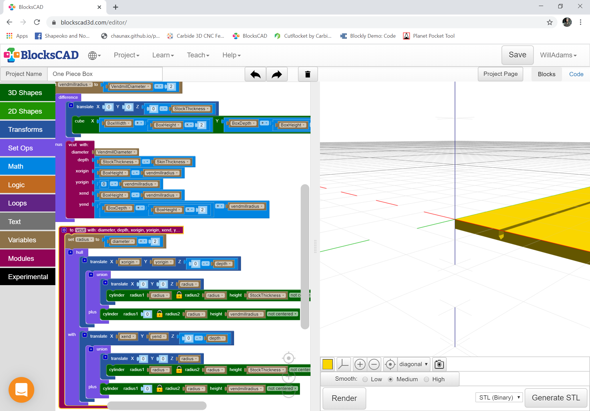
We make a module with appropriate inputs and use it to make the first cut:
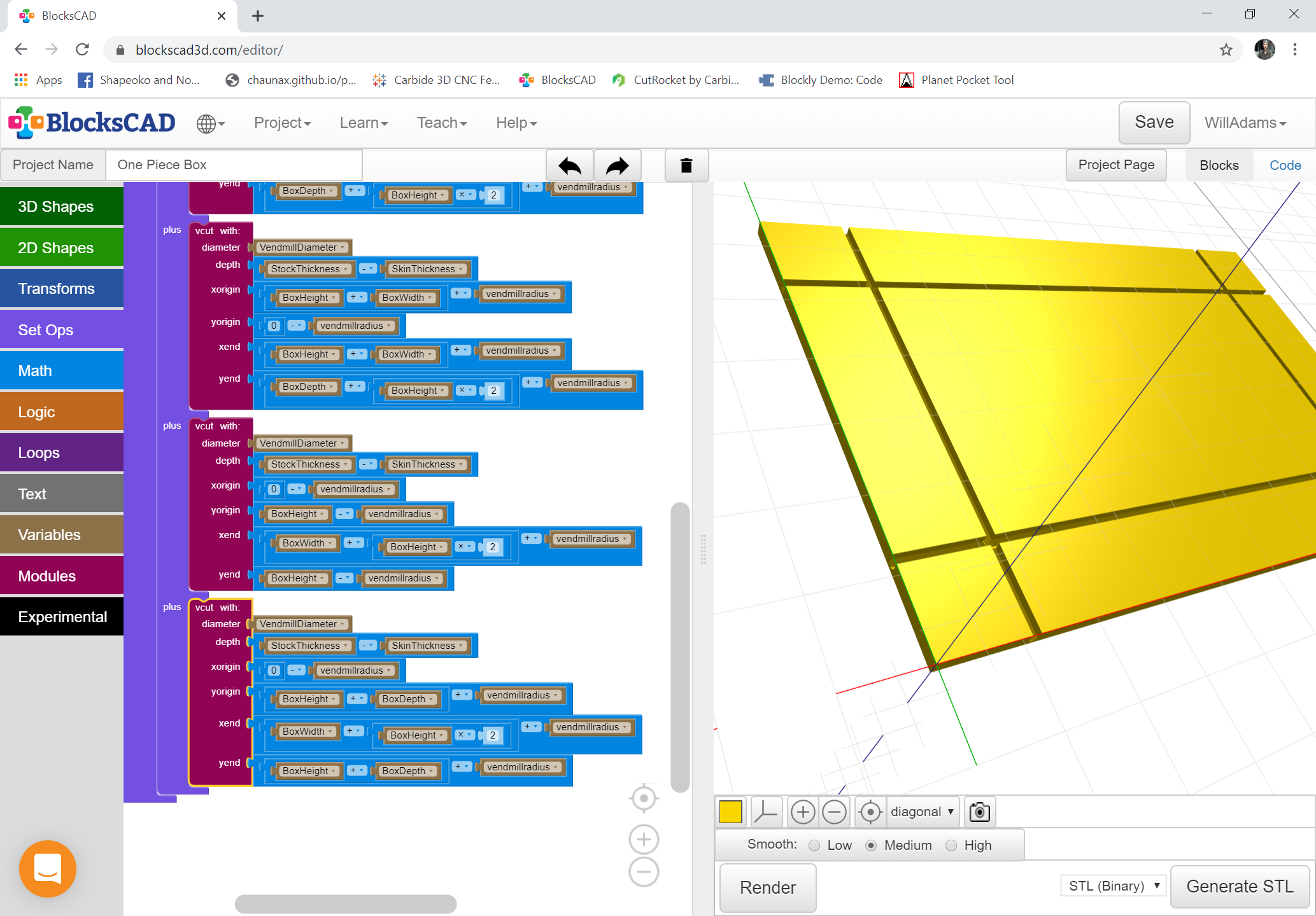
Actually, that points out a flaw in my logic — we need to not offset by the radius — the tip of the V endmill needs to follow the edges of the box. Deleting a bunch of vendmillradius moves.
Wouldn’t this be an easy thing to do with a 90 deg V-bit in CC like @45rpm has shown in the cube videos? It would not have the fancy dado but it would have continuous grain with corners cut at 45deg.
Of course, but the joint wouldn’t be as strong and glue up is a much bigger pain in the butt because everything wants to slide around on you vs. lock together.
Think about a silverware drawer or something else that takes a routine beating.
Well if you leave the onion skin on the outside, there is very little shifting when you clamp together. I agree that a locking joint is better/stronger but you can get the continuous grain look very simply.
… I suspect the best thing to do for a given lot of lumber would be to do a series of test cuts.
Which is kind of annoying, since probably the folding would work better along the grain than at right angles…
But that raises an interesting idea — why not make such a box with the plywood oriented at 45 degrees — the wood grain at the fold/joint would then be consistent, and I think you’d get an interesting visual appearance, esp. if the base of the box was square.
To expand on that — does the geometry work out if you splayed the box out, or brought it in to make a vessel which was narrower at the top than at the bottom? I’m think it wouldn’t — you should need to model the angles and adjust them to match the angle of incidence of the folds/joinery — but doing so (I guess you’d need a 3D model of the angle and to use a very pointy tapered endmill with a ball tip) would be a an interesting extension to the project.
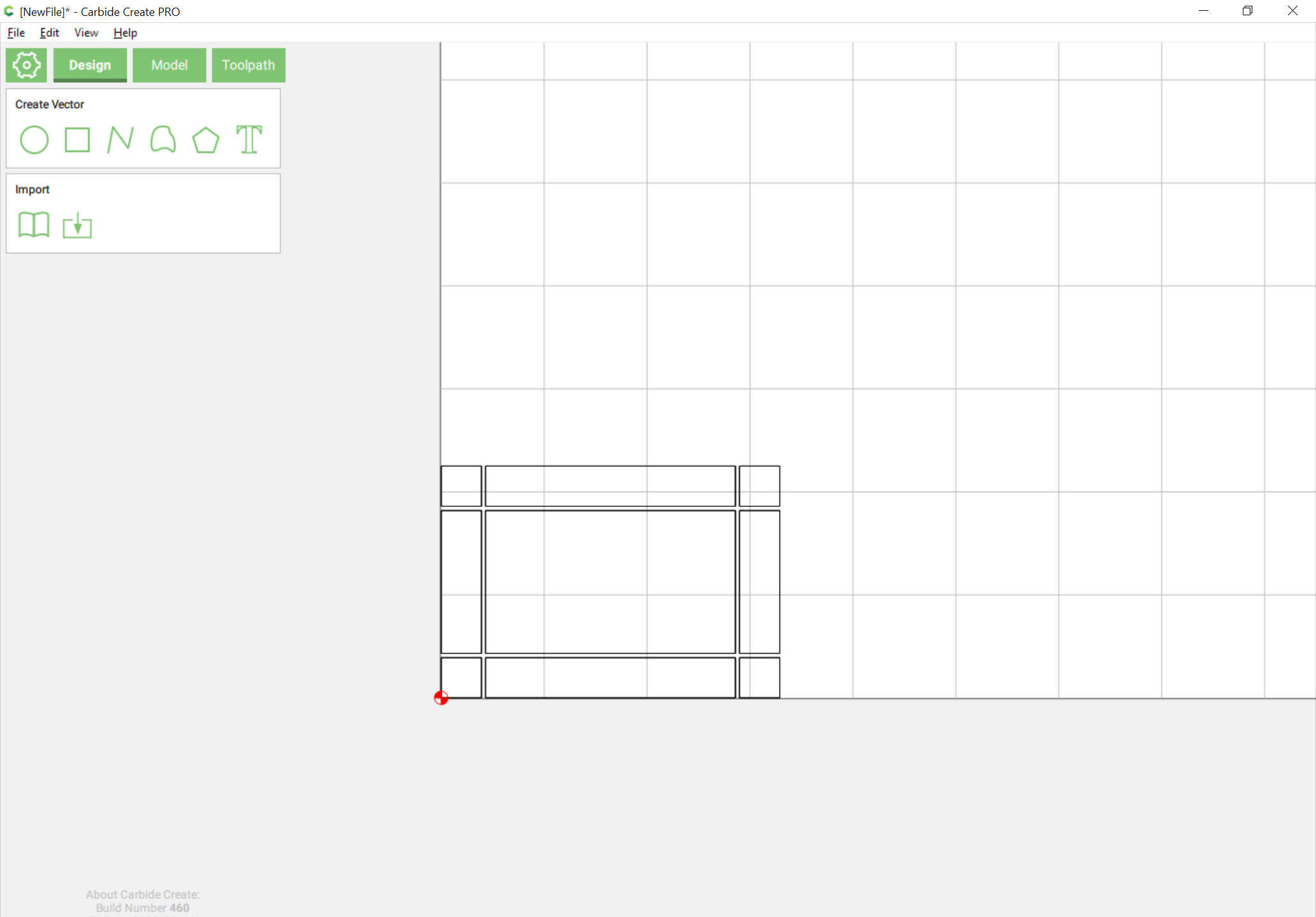
If anyone wants to try this and has a suitable piece of stock they’re willing to sacrifice in testing (and a suitably pointy endmill) I’ll gladly try to work up a test file — it’ll probably have to be exported as an STL with CAM done in MeshCAM or something similar.
I’ve never had much luck “folding” wood in any direction. Seems the only way for me to do this would be the tape-and-cut-thru-the-wood-and-not-the-tape method from the above video.