Thanks for the clarification!!!
Am I missing something or is the display, 3D and tool paths,
no longer in perspective?
1 Like
I think we switched it to orthographic when we shifted to the new renderer. I’m not sure if we’ll leave it or not- it’s just what the new code was setup to be. Your opinions would be helpful.
1 Like
Personally, I would rather have perspective. It just helps me visualize better.
1 Like
I vote orthographic. Snapping to any of the 8 std orthographic views would be super cool (Top, Front, Right, Left, Back, Bottom, Iso, Tri)
When rotating the part to see if features line up, or verifying toolpaths, it’s much easier to line things up in orthographic.
4 Likes
I get that, I guess I am just used to using Fusion360 Perspective w/Ortho faces.
Perspective is nice if you’re doing mock-up pictures for your customer, or viewing a more realistic rendering of the part. Ideal solution would be a toggle so we could use either. 
5 Likes
One more for the weekend- 867 is up at the beta page
We fixed a few bugs, but we added an angled plane command, which lets you create components made up of… angled planes.
To use it, select your geometry normally, then set the locations and heights of the three reference points, and you’re good to go.
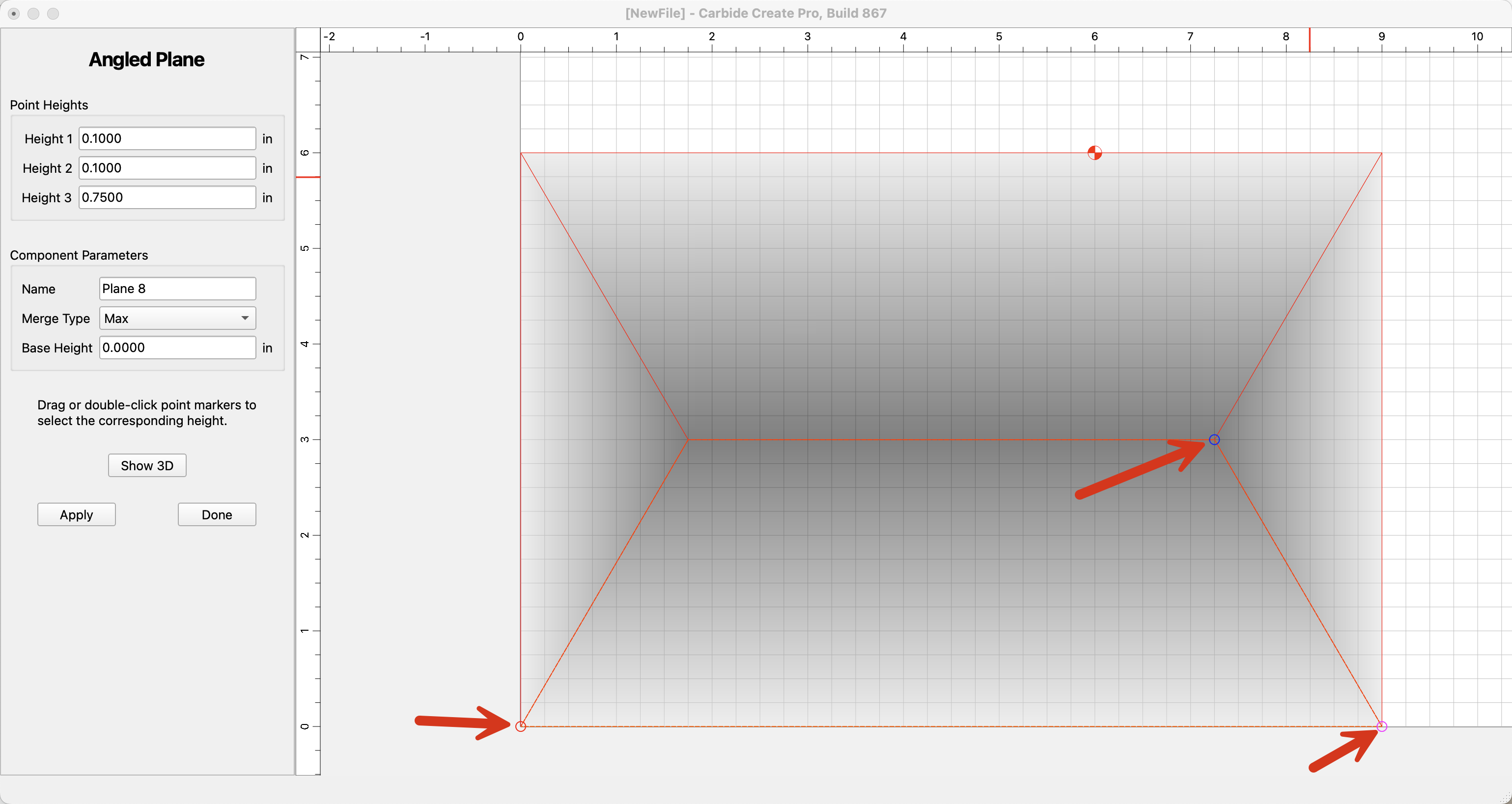
This lets you create geometries that were tough to do any other way in Create Pro, like this:
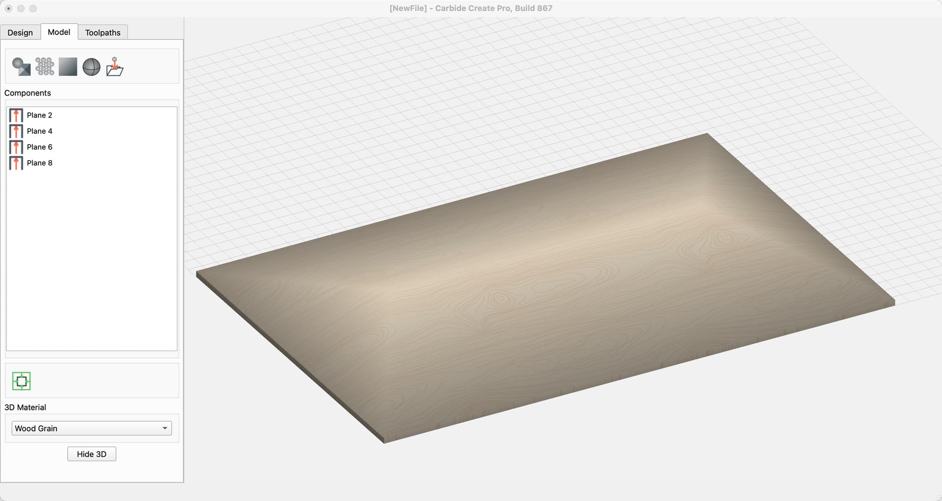
Which is made of 4 angled planes:
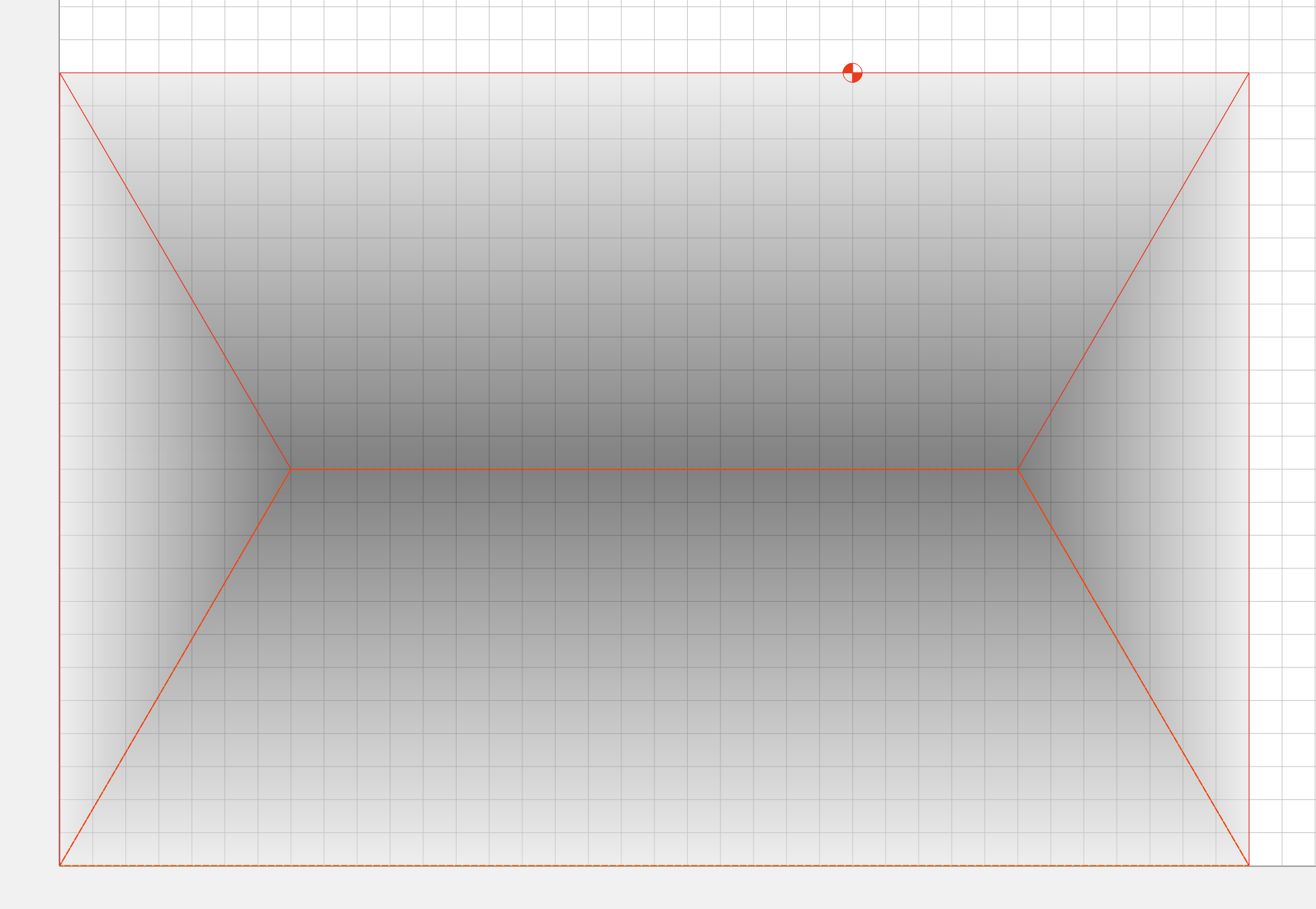
These planes are generated on the fly, so you can reopen and fully edit them after they’re created.
Now, there’s a small quirk we haven’t fully decided how to handle yet. To make that shape above, we didn’t use “Add” as the merge type; we used “Max”. Because the planes can overlap one another at the boundaries, the Add option can create spikes. I’m not sure whether this is inherent in the heightmap model we use for 3D. We’ll see.
Second, the engineers in the crowd may want to define angles directly, rather than heights. We have ideas for how to incorporate that into the UI, but the support tickets we’ve received suggest points/heights are the primary way to define the planes for most user applications.
This is a work in progress, so we may need to change the file format again if we missed something. That means planes saved in this version could be incompatible in future releases if we find a problem. We don’t expect that to happen, but it could.
Try it out.
7 Likes
This is really cool in the few min I’ve played with it. I’ve crashed the 3d view a bunch by making changes and previewing on existing projects and I think it trying to re-calculate the toolpaths was a bit too much, lol. The only small thing which you’re probably planning anyway, is it would be great to have numbers on the points and/or the text in where we can enter the heights matches the color of the point it is associated with. Otherwise, it’s hard to know which one is doing what.
That aside, it looks like a pretty cool and powerful tool. thanks!
I think we’ve taken care of all the crashes from the new renderers, which seem to be due to different backends (OpenGL/DirectX) and different video drivers.
If you get a crash, be sure to submit it.
We have ideas, but we like to start with the simplest option. In the testing we did, clicking the marker to select that height was better than expected. The colors, which we left in for now, turned out to be less helpful than expected.
1 Like
It never crashed out of the program, i would just be in the 3d view and suddenly it would go back to the 2d view. But it was also maxxing my processor to calculate the 3d rough toolpath so I figure that’s a big part of what’s going on.
We don’t throw the “c” word around higgledy-piggledy; you can only use that term for a “true crash”. (We’ll allow it this one time)
There are some triggers that cause the view to reset with toolpaths update, so it’s possible that 3D roughing completing in the background is to blame.
1 Like
I don’t have Pro, but I am trying a few abusive models.
The is an option under View → use ANGLE Rendering.
Is there any reason not to select this ?
Rob,that is a great upgrade and the angle is superb working very well,thanks Rob
1 Like
I’m going to need a video because my 72 year old self can’t wrap my brain around this.
I’ve been experimenting a bit.
Basically there are 3 points:
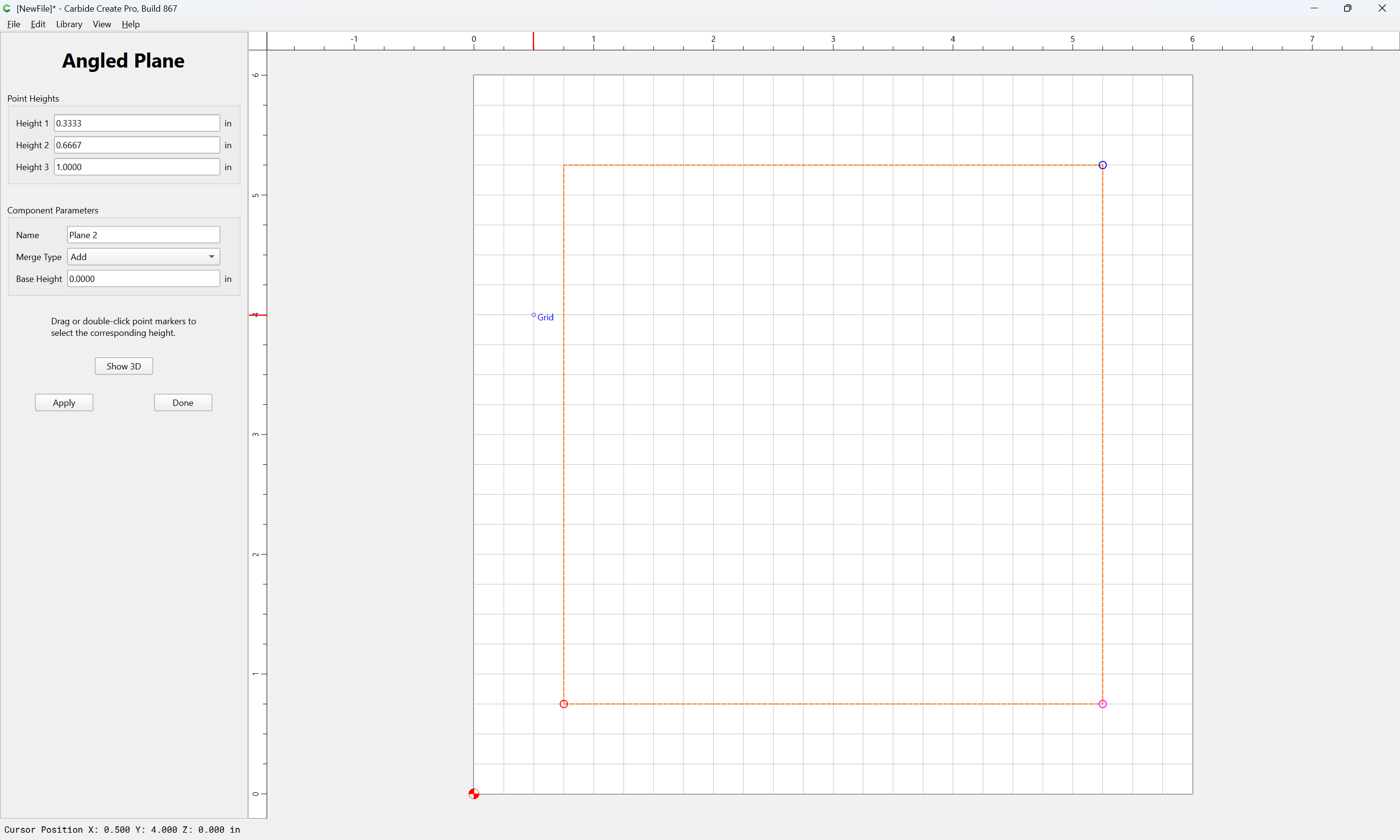
and based on where they are dragged/positioned, one gets different levels:
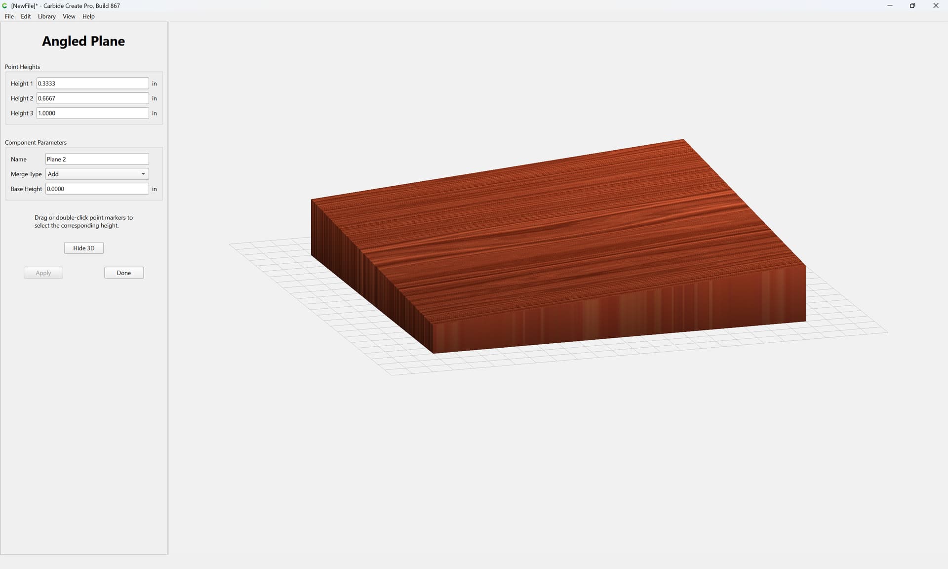
1 == red, so in above is lowest and 0.333"
2 == magenta, so in above is mid-height and is 0.667"
3 == blue, so is tallest at 1"
If one drags them around one can alter the angle:
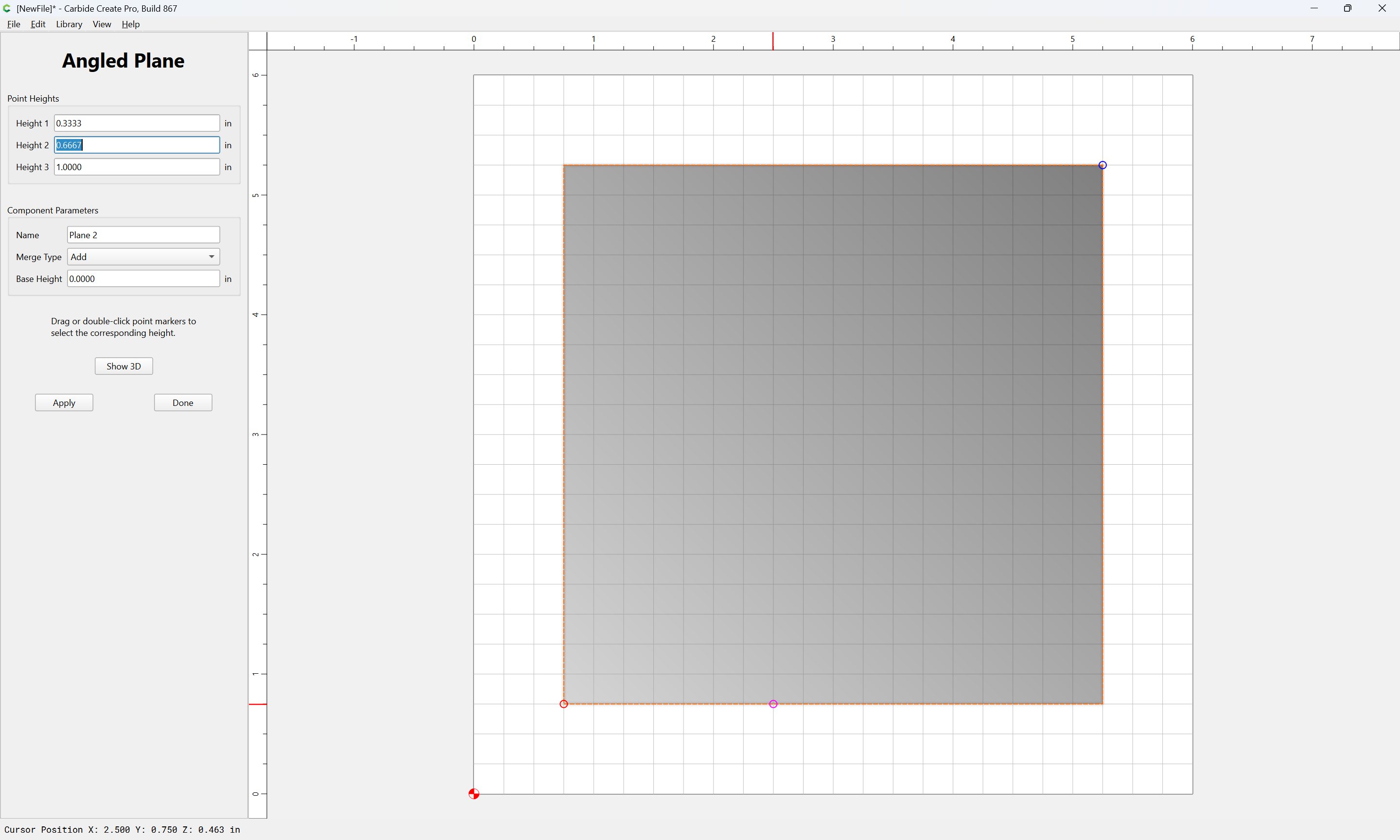
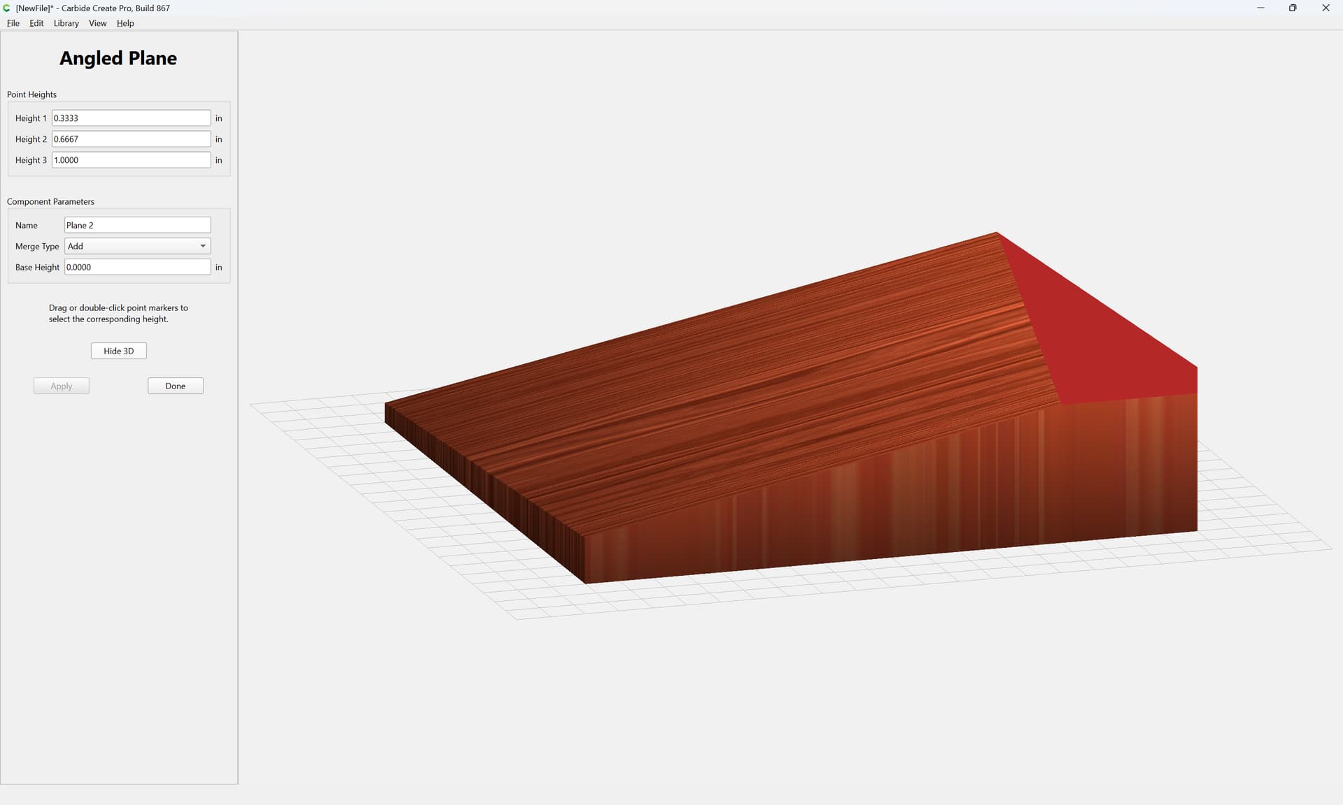
(which can cause the angle to lift up higher than expected)
but adjusting the values:
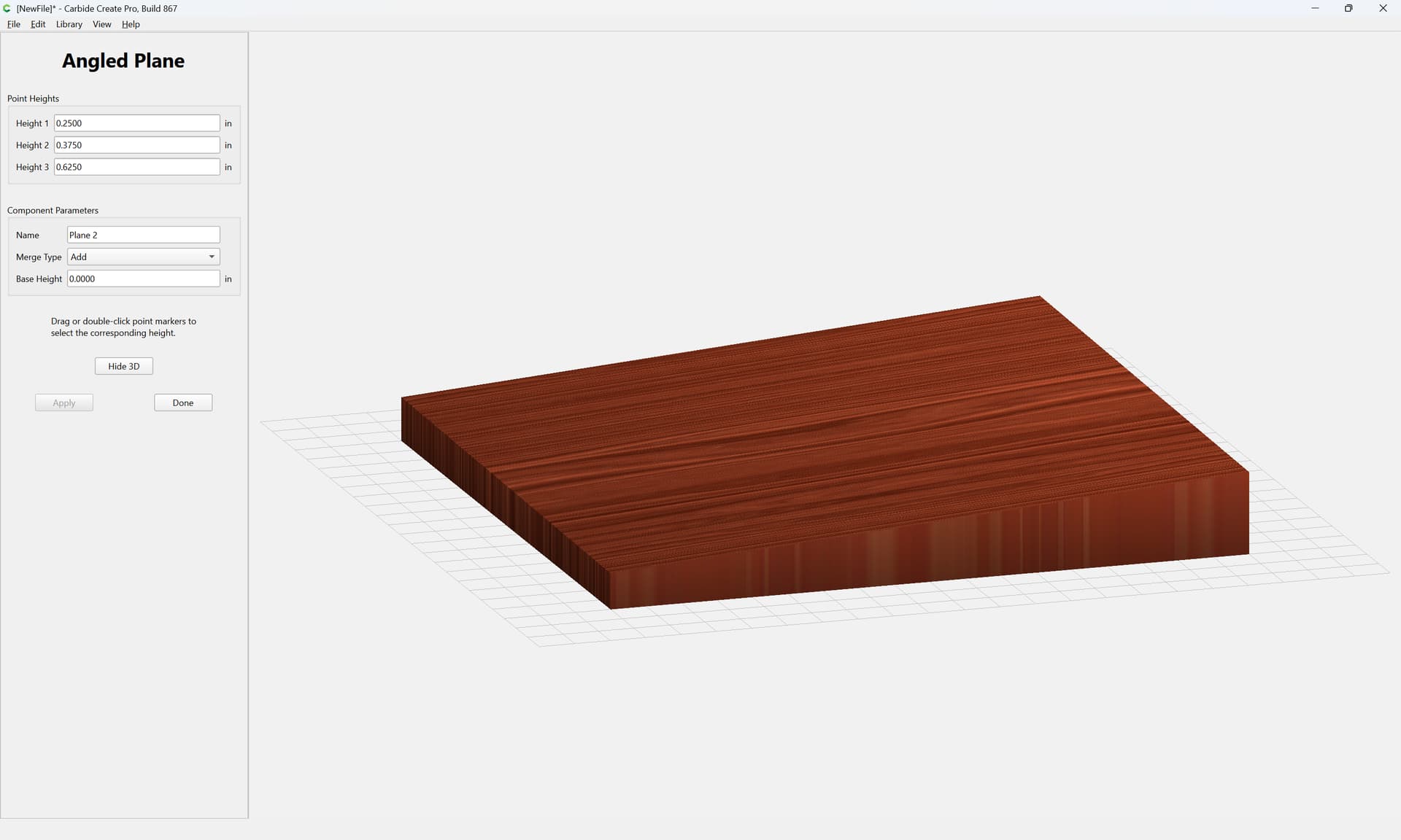
will bring it back into line.
If you have an effect which you are trying to achieve, the position/values should be pretty obvious, but if you have difficulty, work up a dimensioned drawing and post that and we should be able to work through this with you.
I did just discover that double-clicking on any of the points will cause that value to highlight on the left so if you’re trying to remember which one is which, that’s a quick way to figure it out.
2 Likes
You guys are awesome. I sent a request yesterday and you incorporated the solution into Carbide Crete Pro today. As to the “Angled Plane” feature, I tried to work up my “wedge/shim/angled plane” tonight, and I think it would work if I run it. I’ll try tomorrow, but I’m curious.
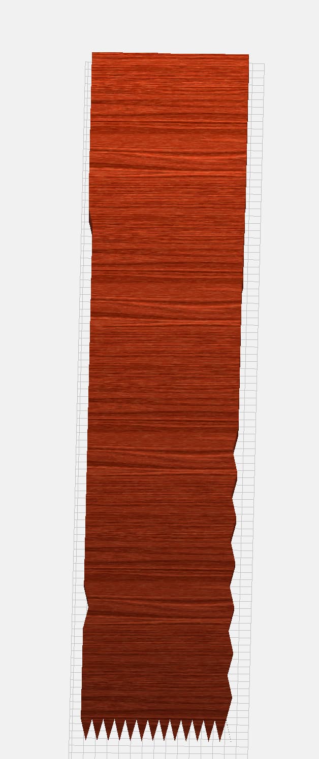
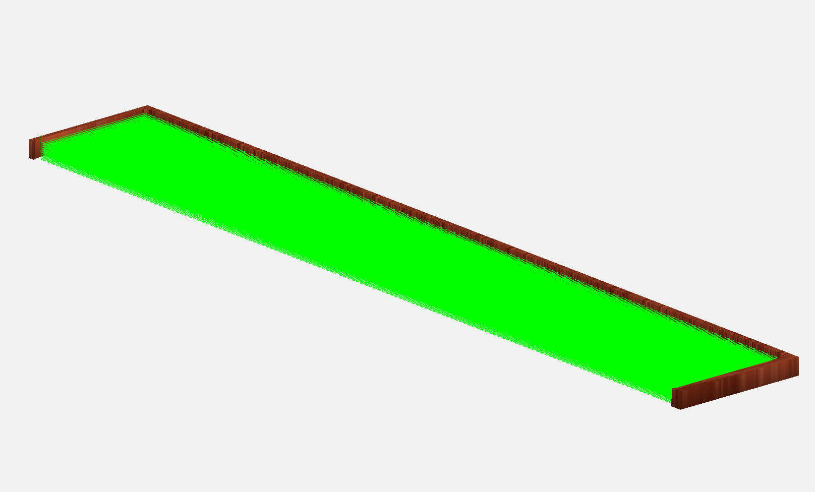
I’ve included a few screen shots, but the “Show 3d” rendering looks all distorted in “Model” view, and “simulation” view in Toolpaths. I’ll attach my CCPro file as well.
Neck wedge for guitar.c2d (56 KB)
1 Like
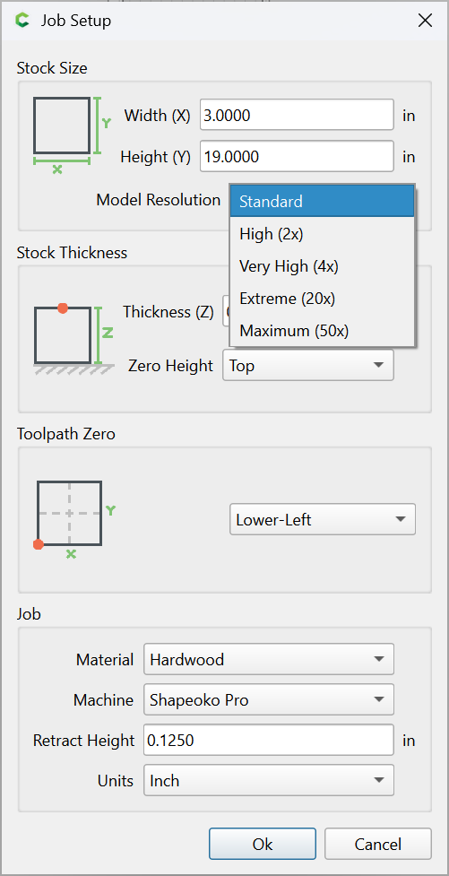
The model quality is set rather low:
Increasing to Max seems à propos:
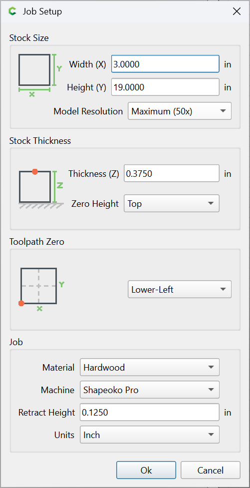
You are only modeling a subset of the stock:
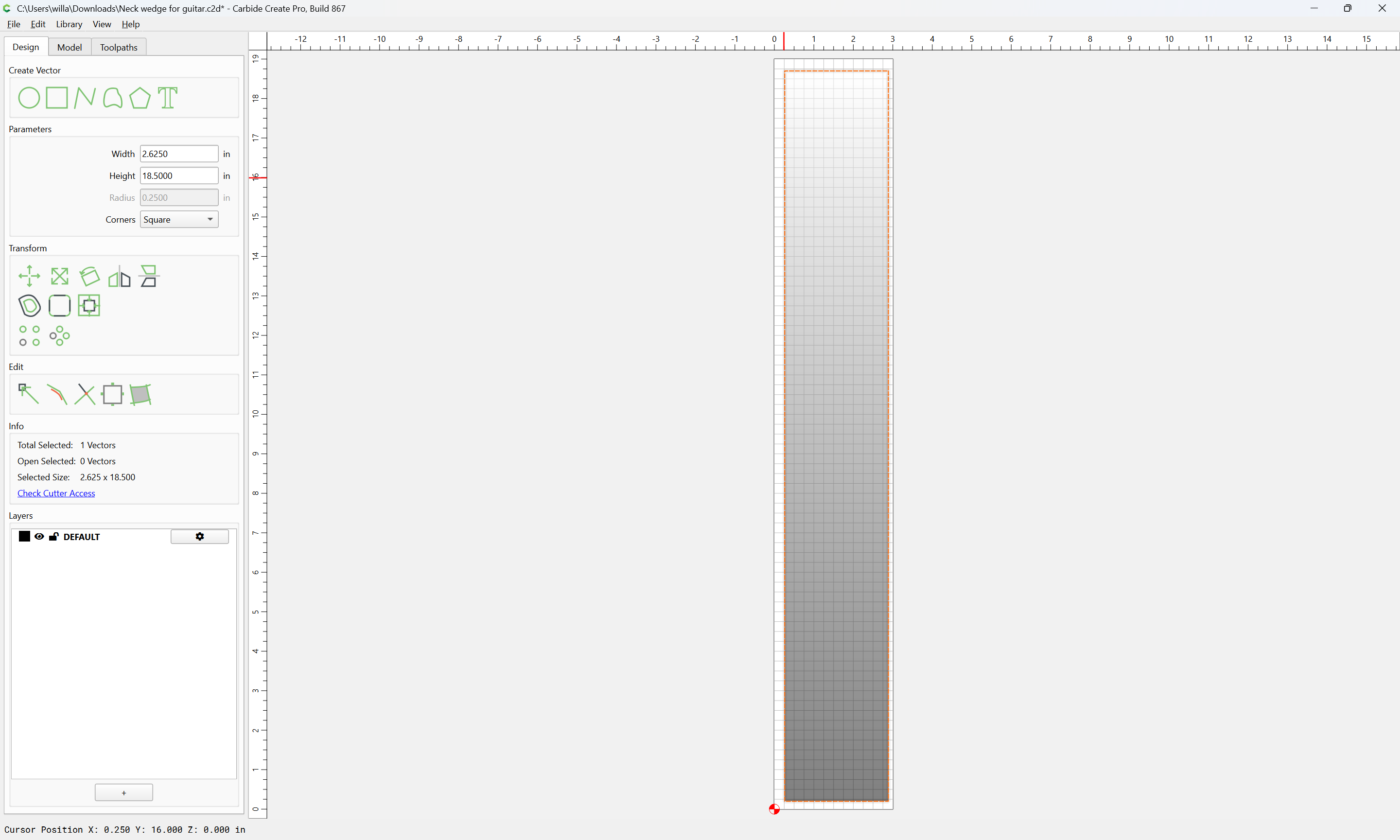
You are trying to model to a thickness of 0.0:
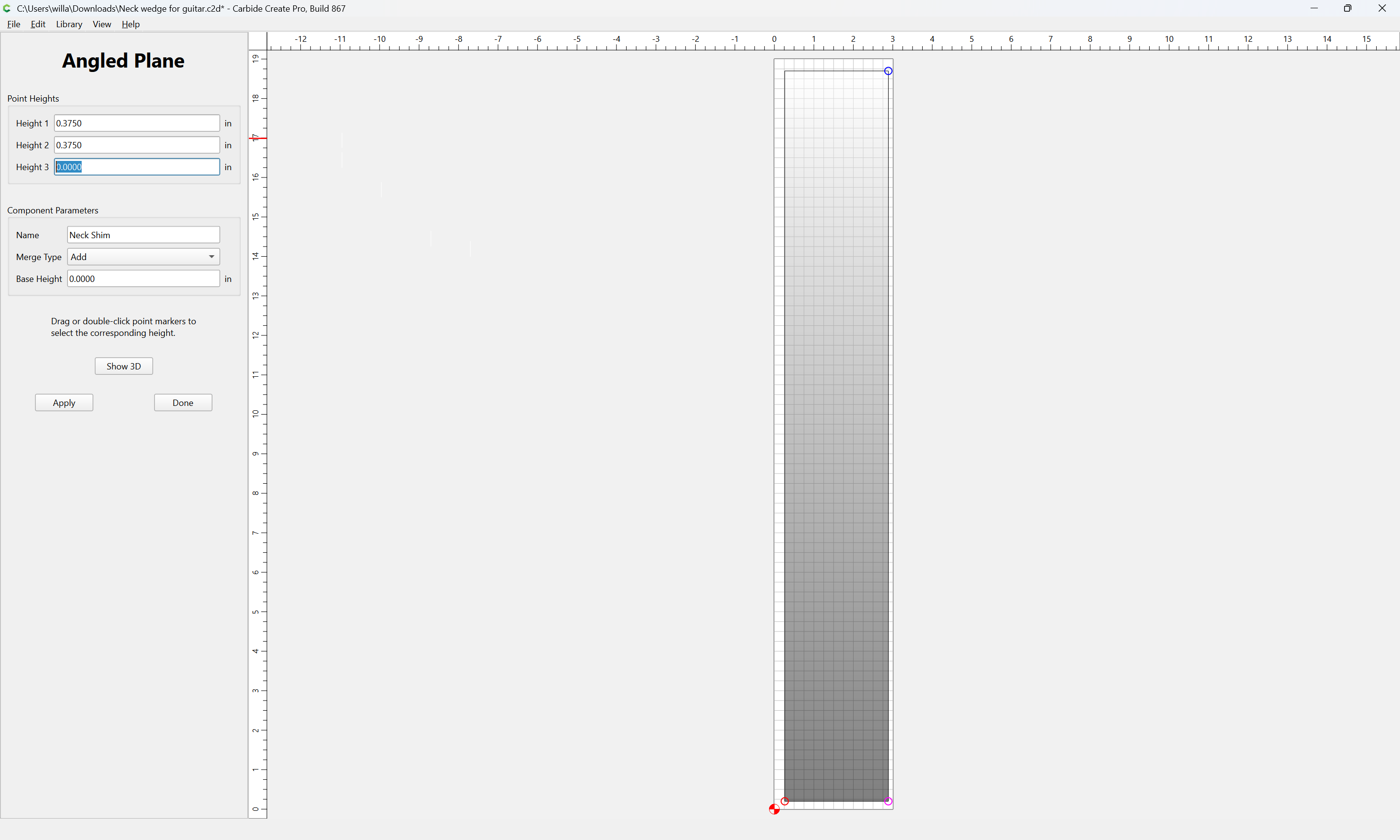
IME, it would be better to model more, then cut away, and since the neck doesn’t actually go down to zero, it would be better to model the actual dimensions. This wedge looks to be for a guitar fretboard, so something like:
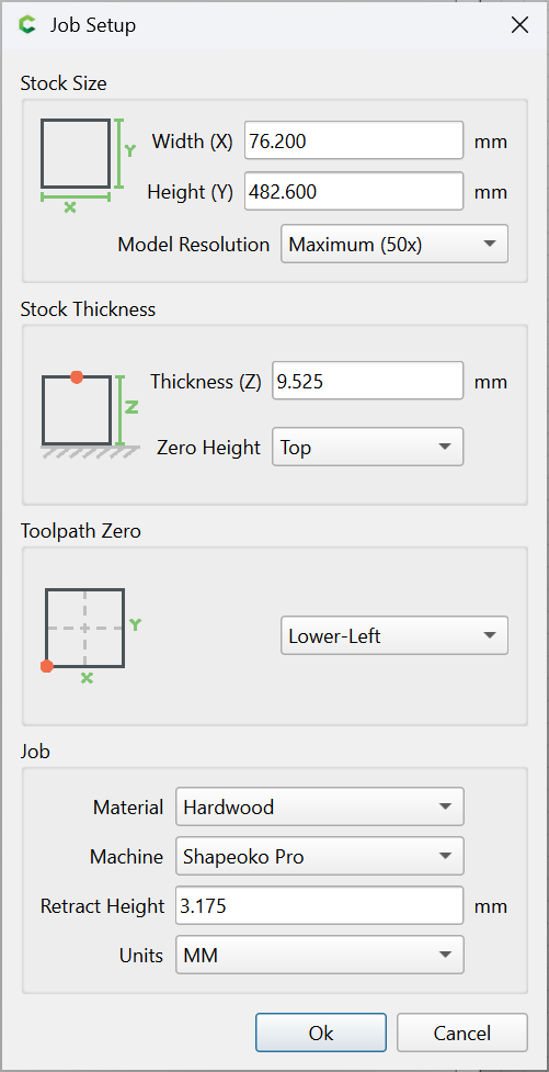
Switch to metric:
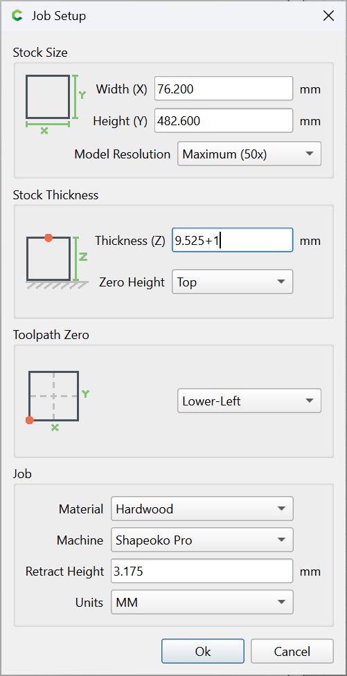
and increase the stock thickness by 1mm:
Draw geometry which matches the Stock dimensions:
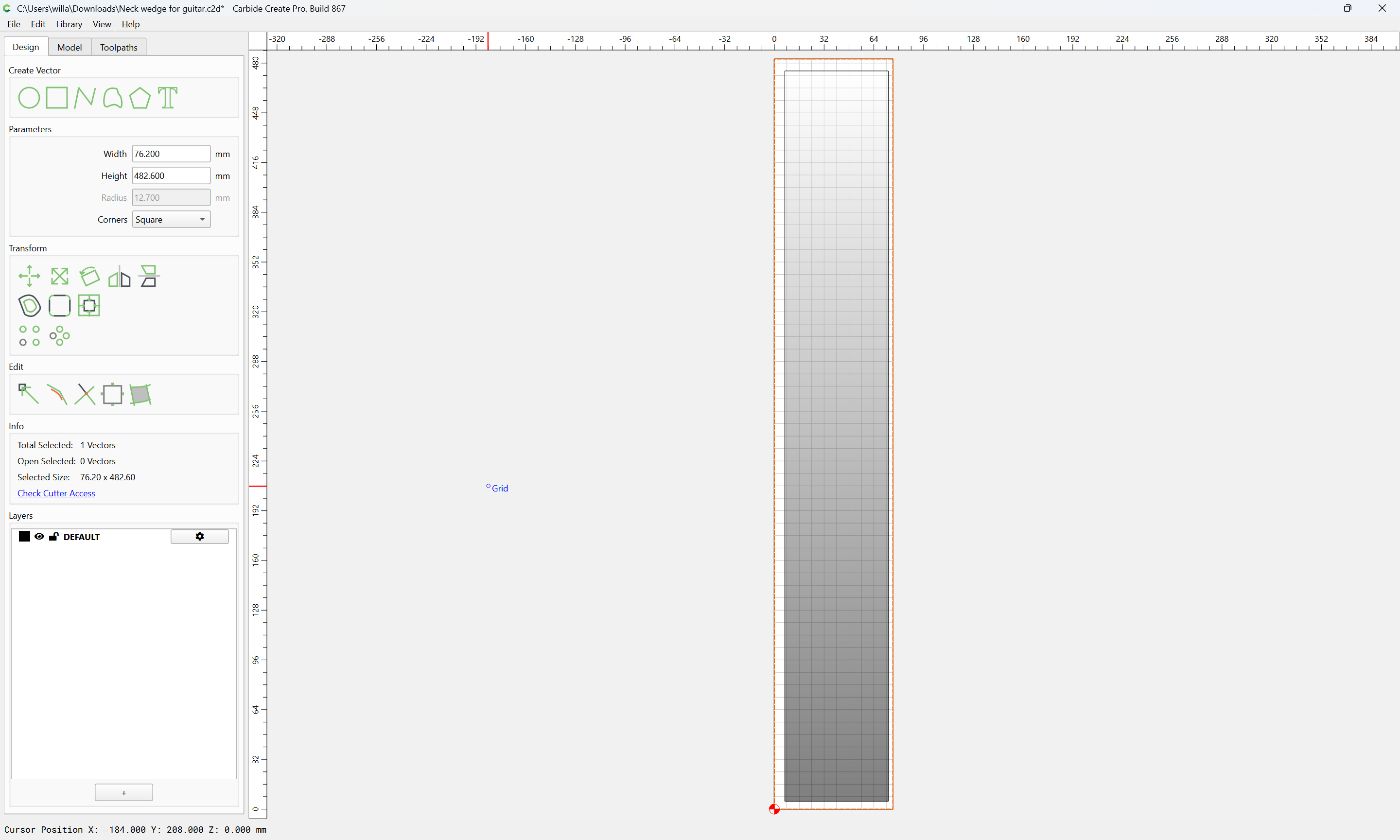
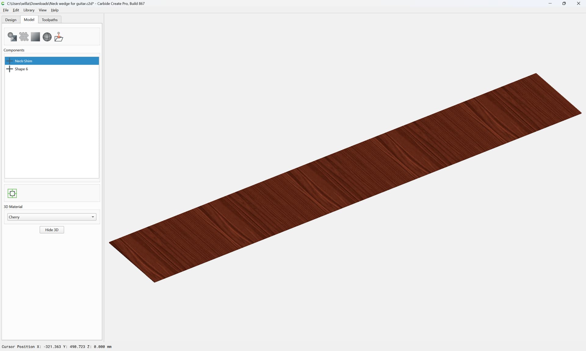
Model that to a thickness of 1mm
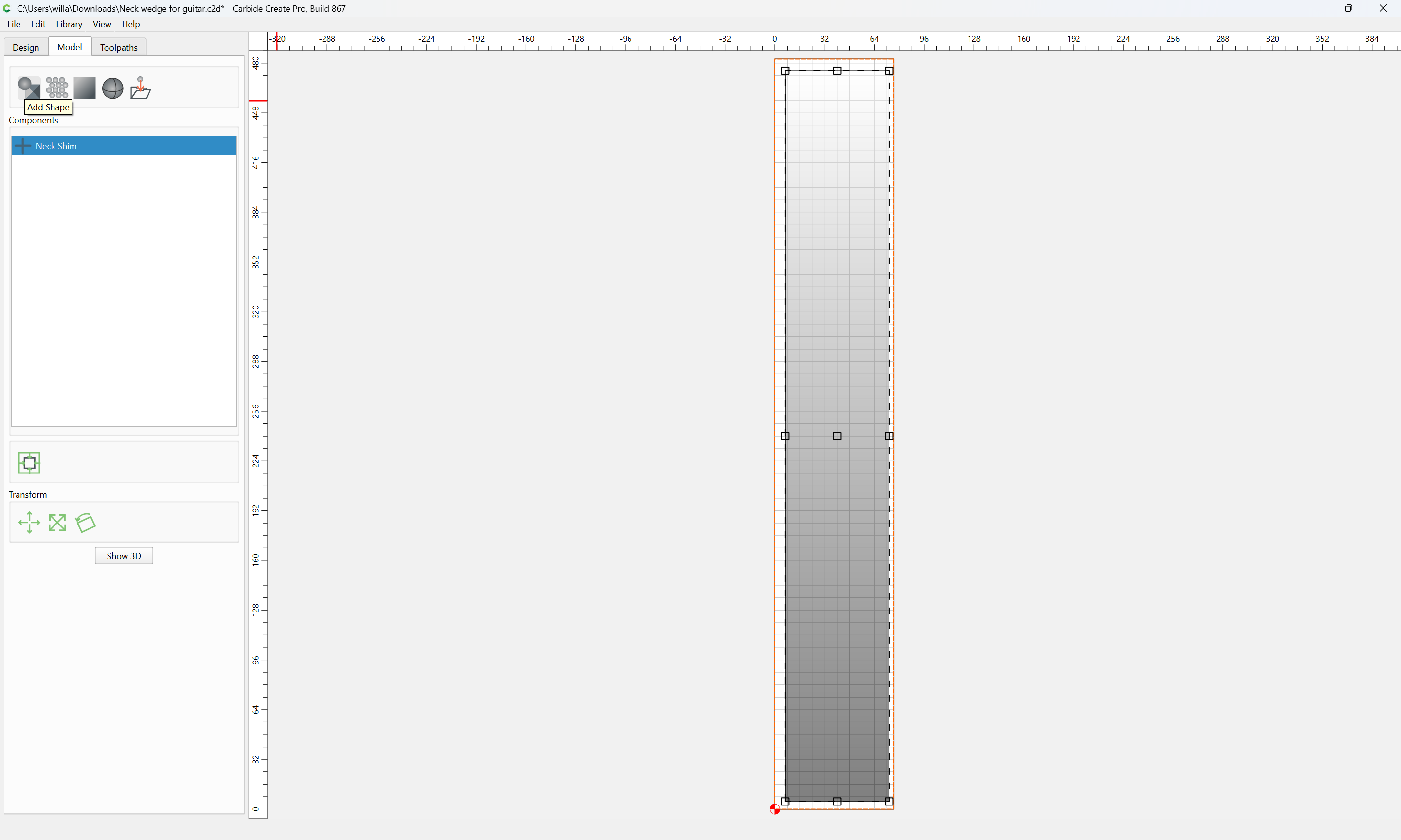
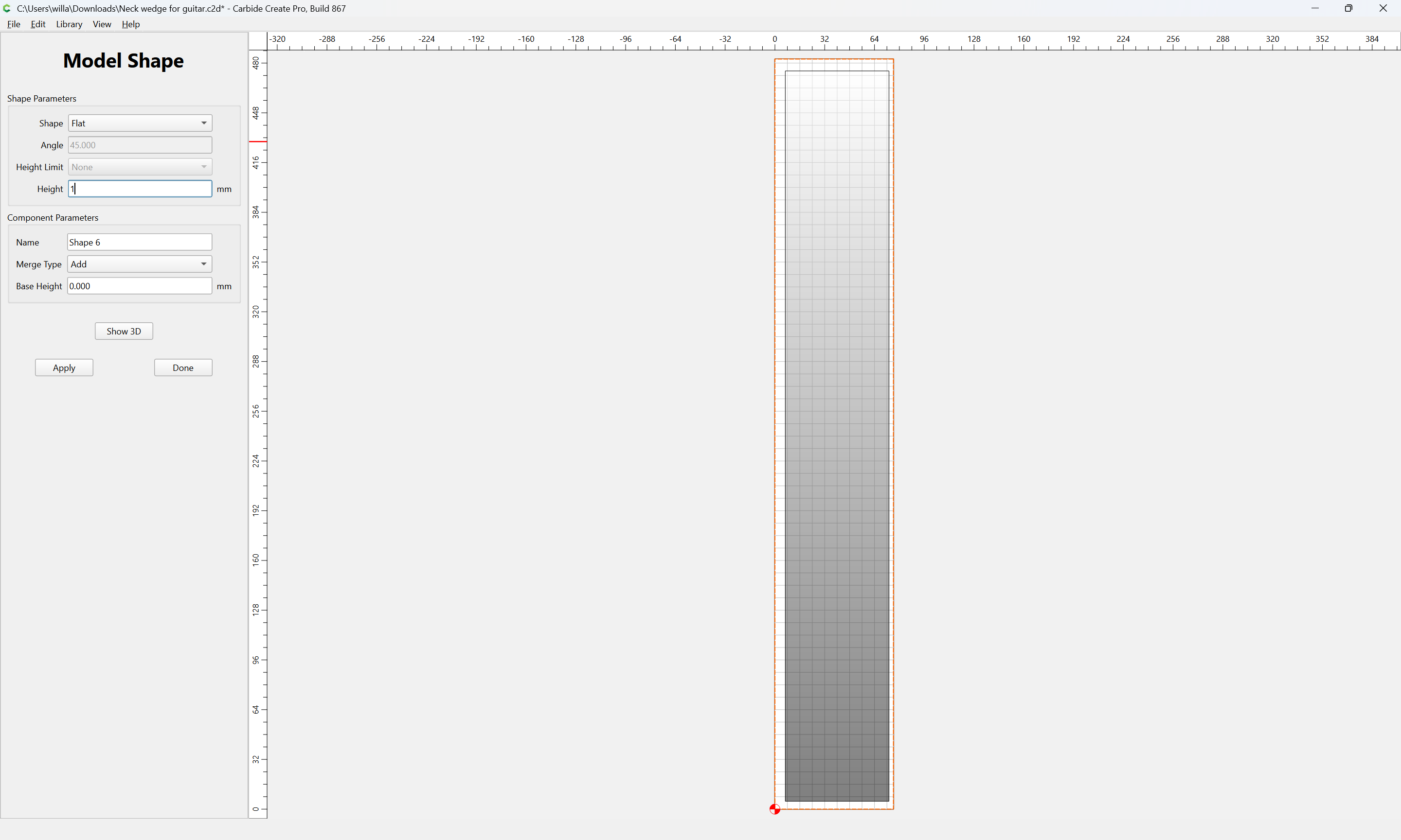
Go back to Design and select the geometry for the angle:
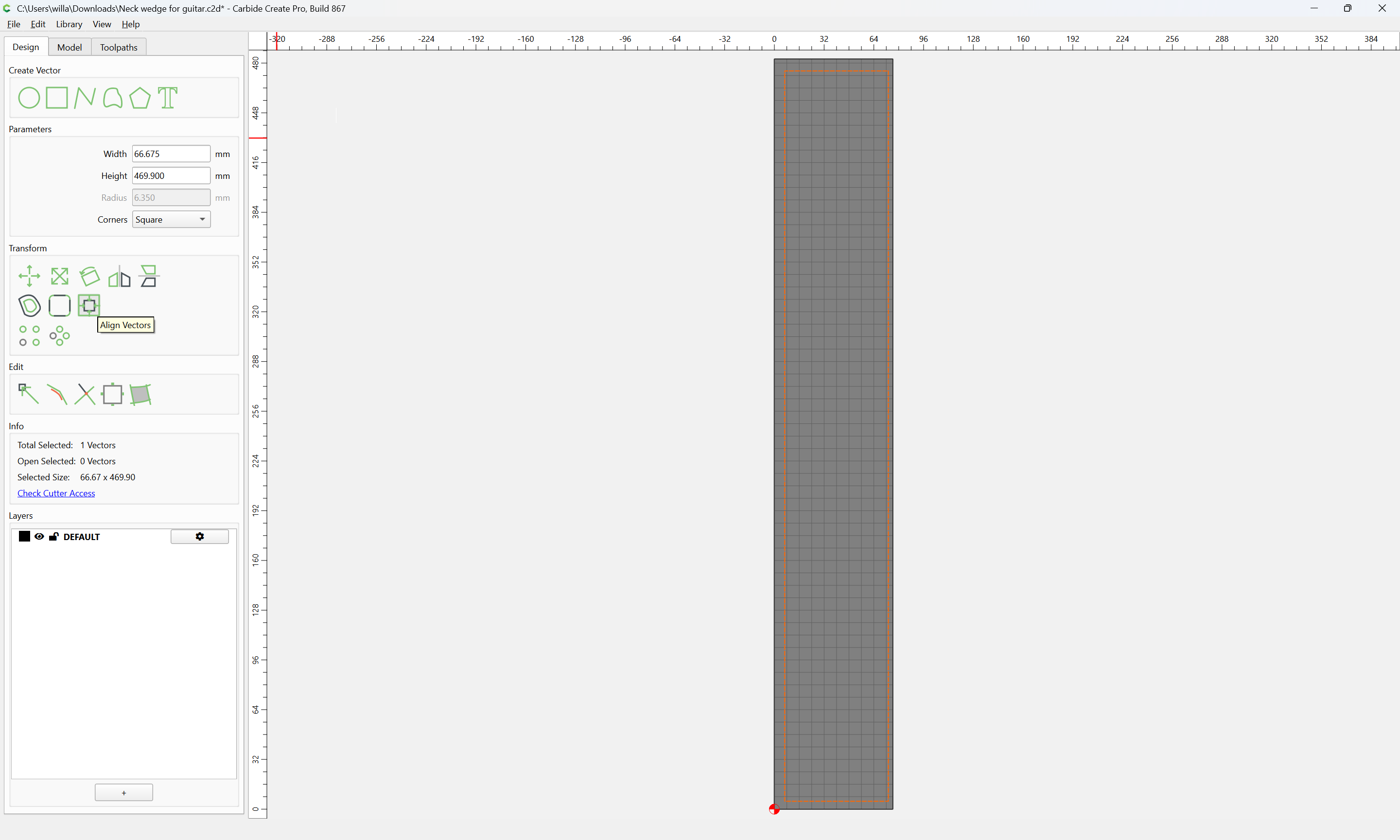
and center it on the Stock:
o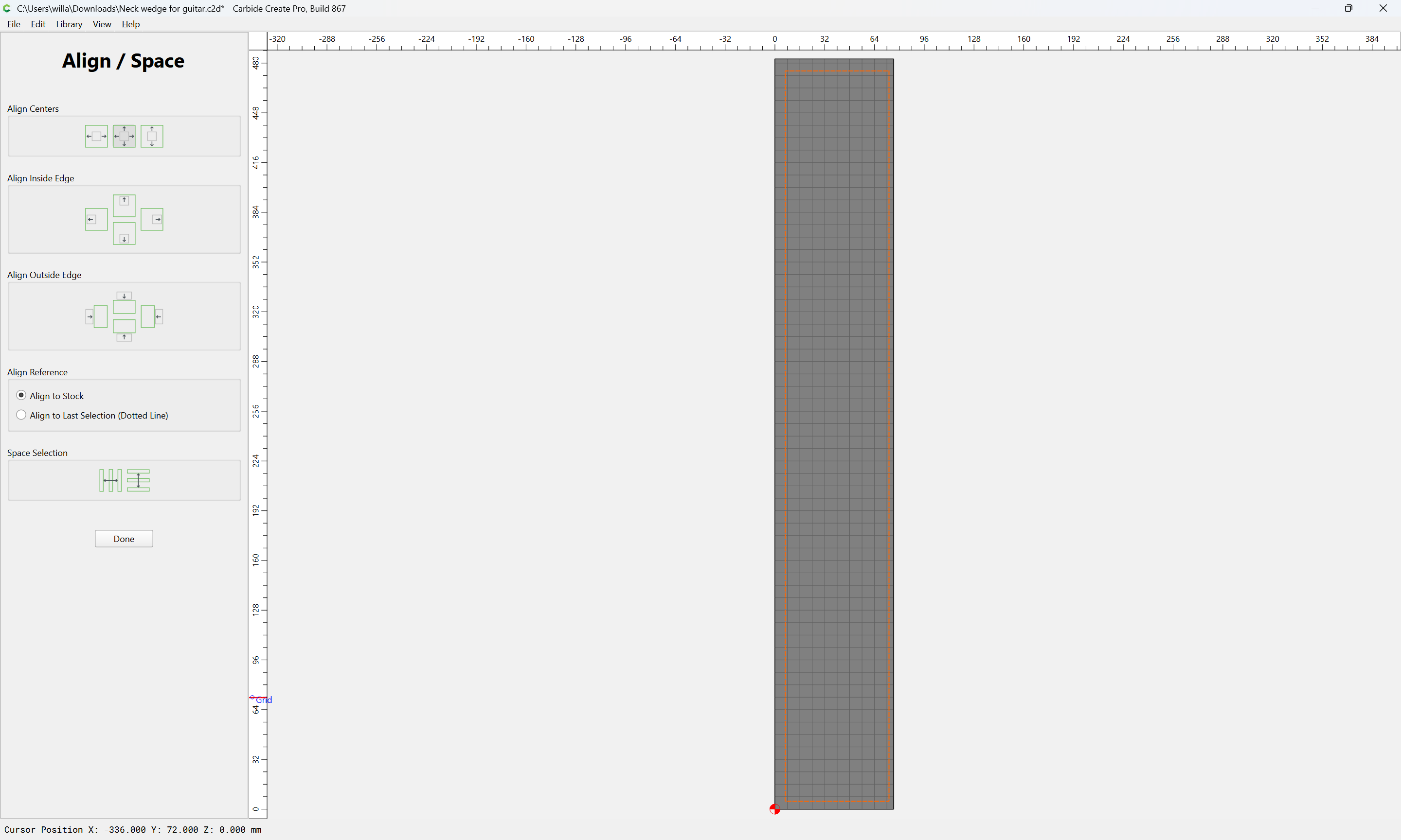

Done
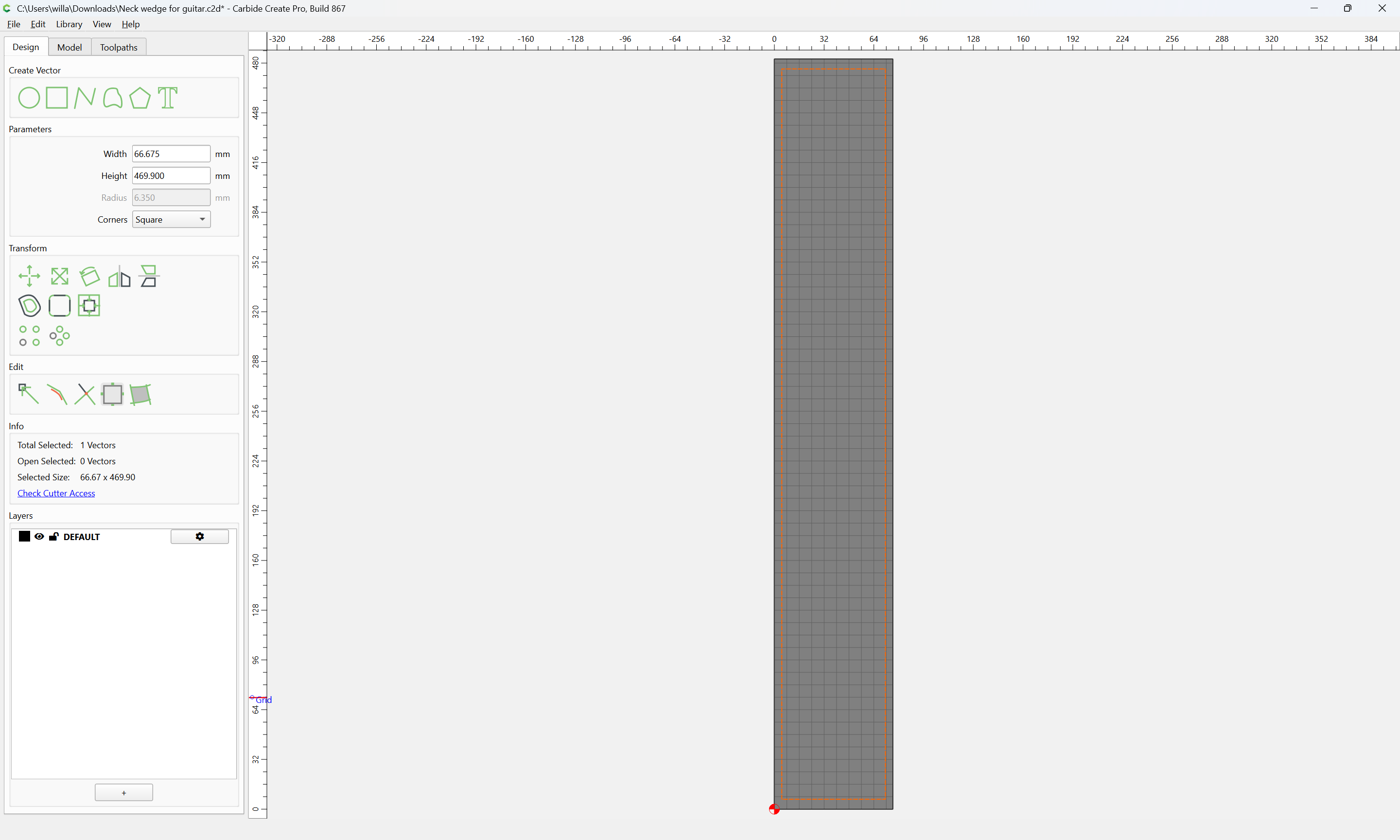
Select the geometry with the Stock Dimensions:

switch back to the 3D Model pane:
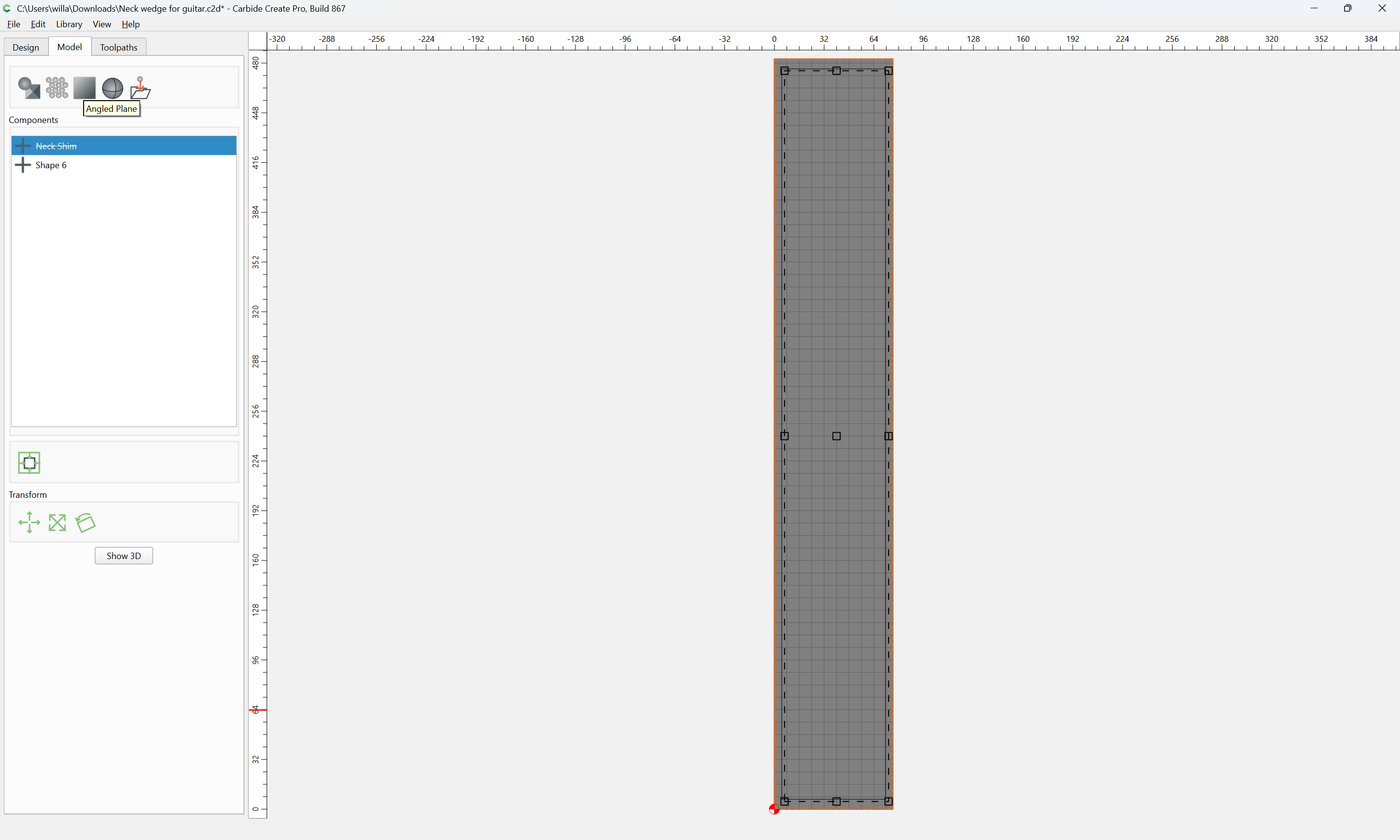
and model it:
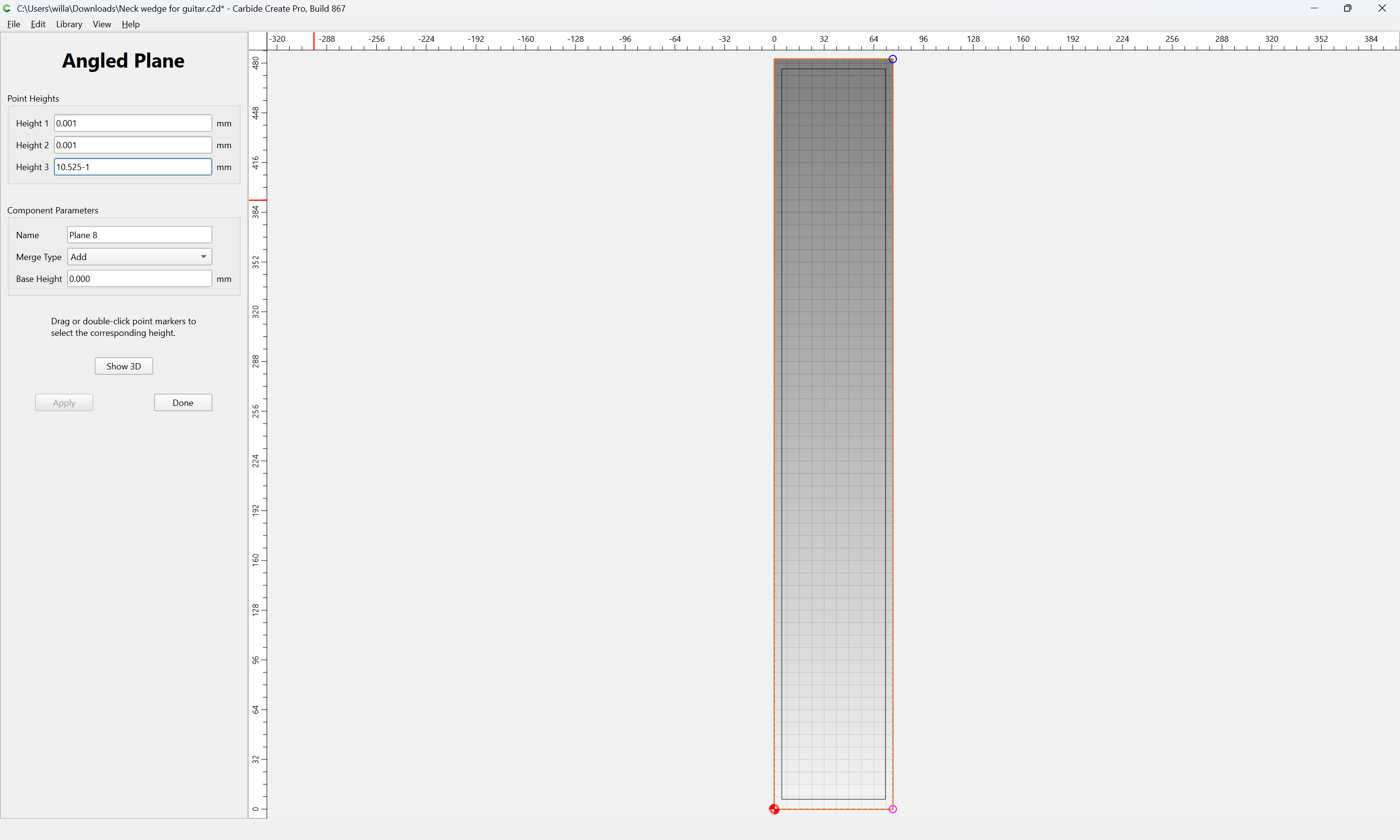
Show 3D:
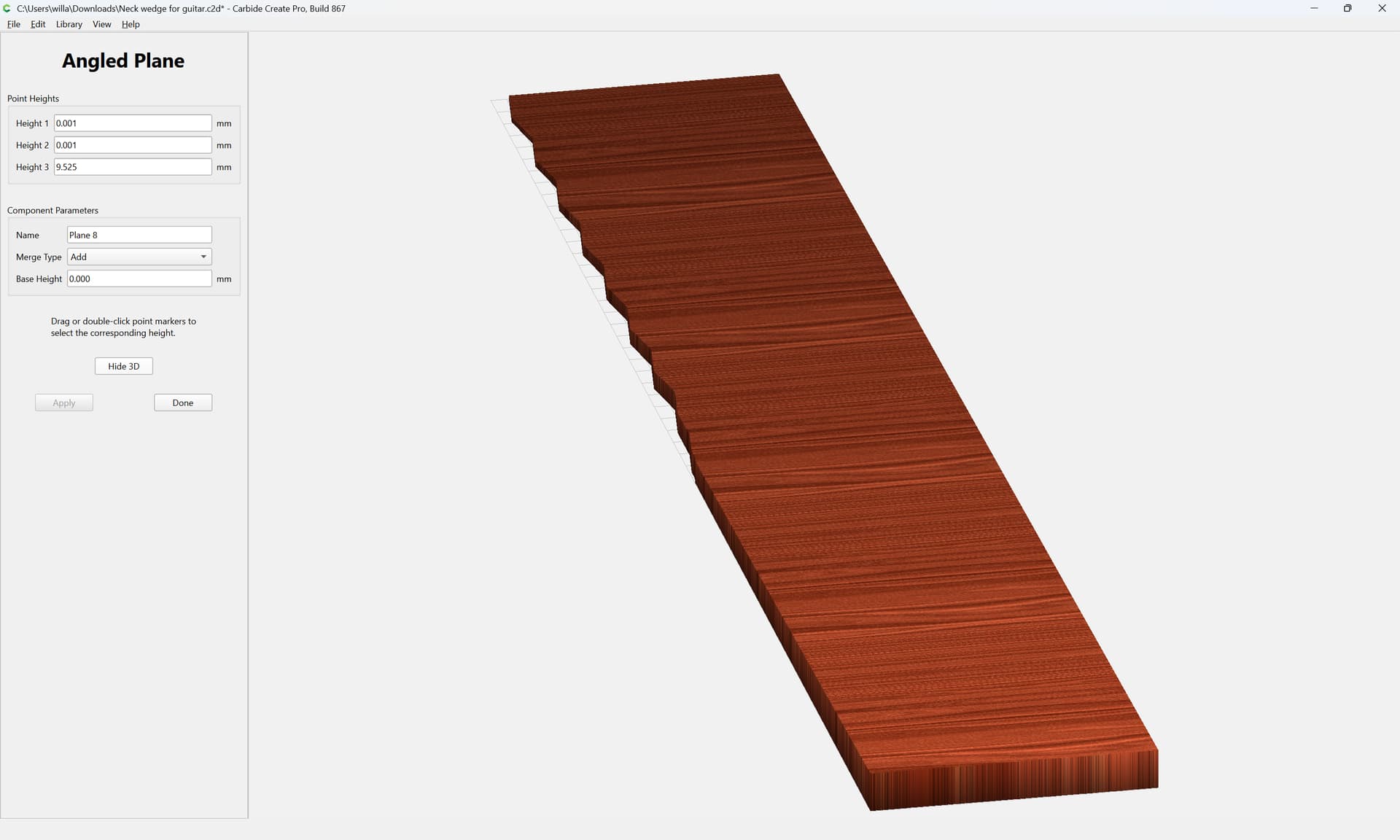
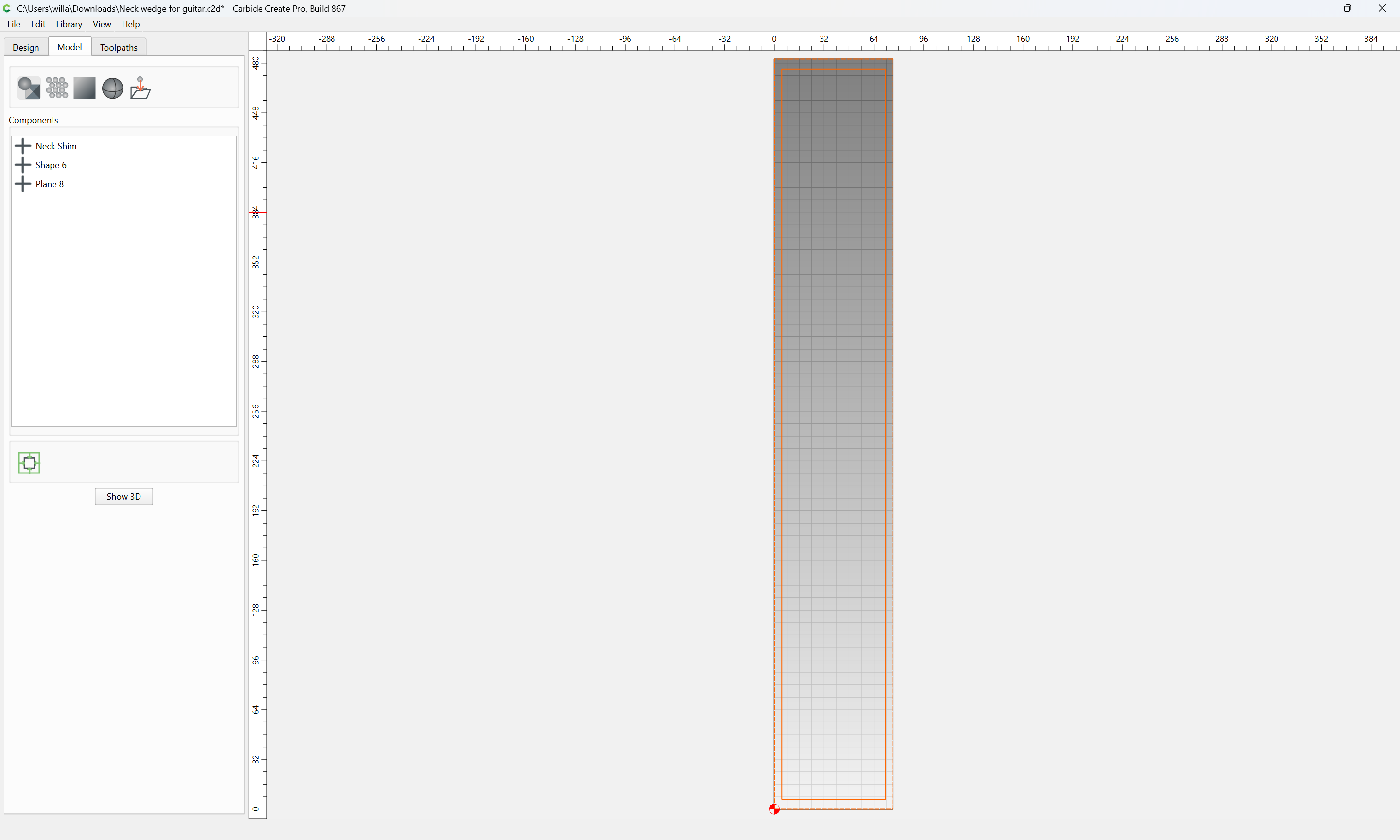
Select all the geometry:
and subtract what is not wanted:
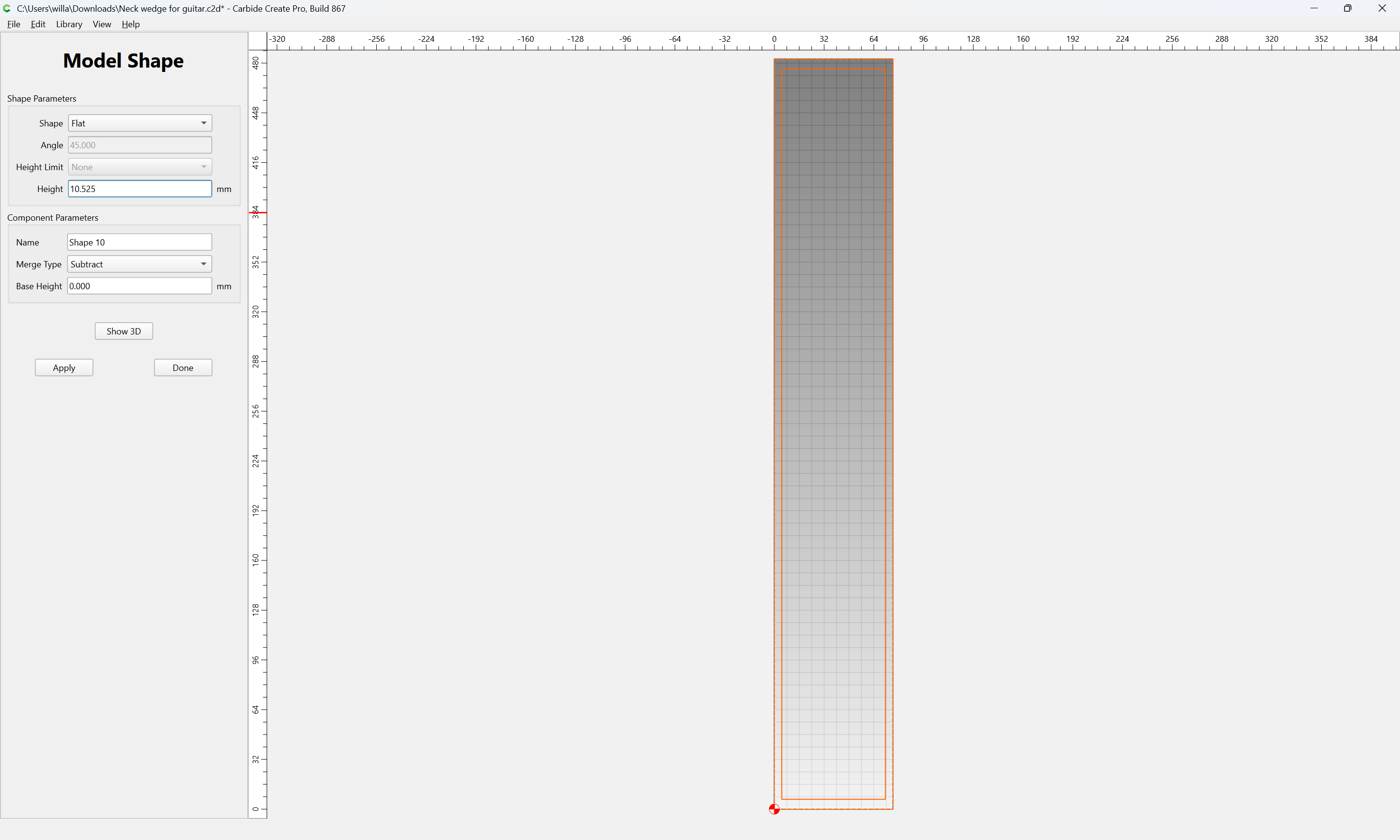
Iterate and adjust these dimensions/adjustments until one arrives at something like:
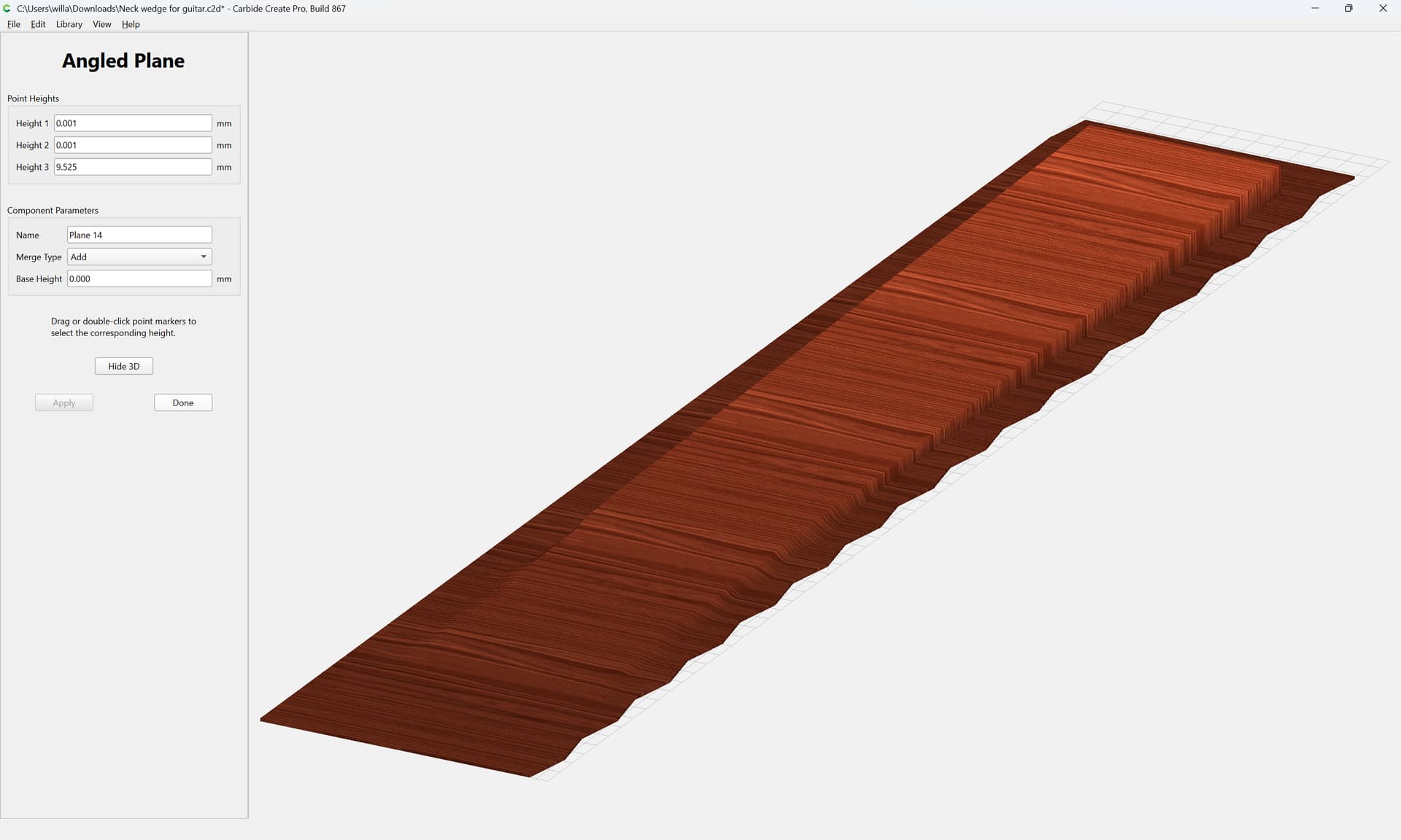
and then use a 2D toolpath to remove the final 1mm of thickness if need be.
(removing the surround as a 3D operation does not work well — not sure if a bug or a limit of the architecture)
I will note that for similar operations in archery, there are specialty tapering sander setups to make limb laminations due to the fragility of the thinned off ends — not sure if this will cut well, and it might be better to use the 3D model to make a tapering fixture, then actually cut the taper using a 2D flat toolpath (facing or a Raster Pocket).
Adding 3D toolpaths and a 2D Cutout one gets:
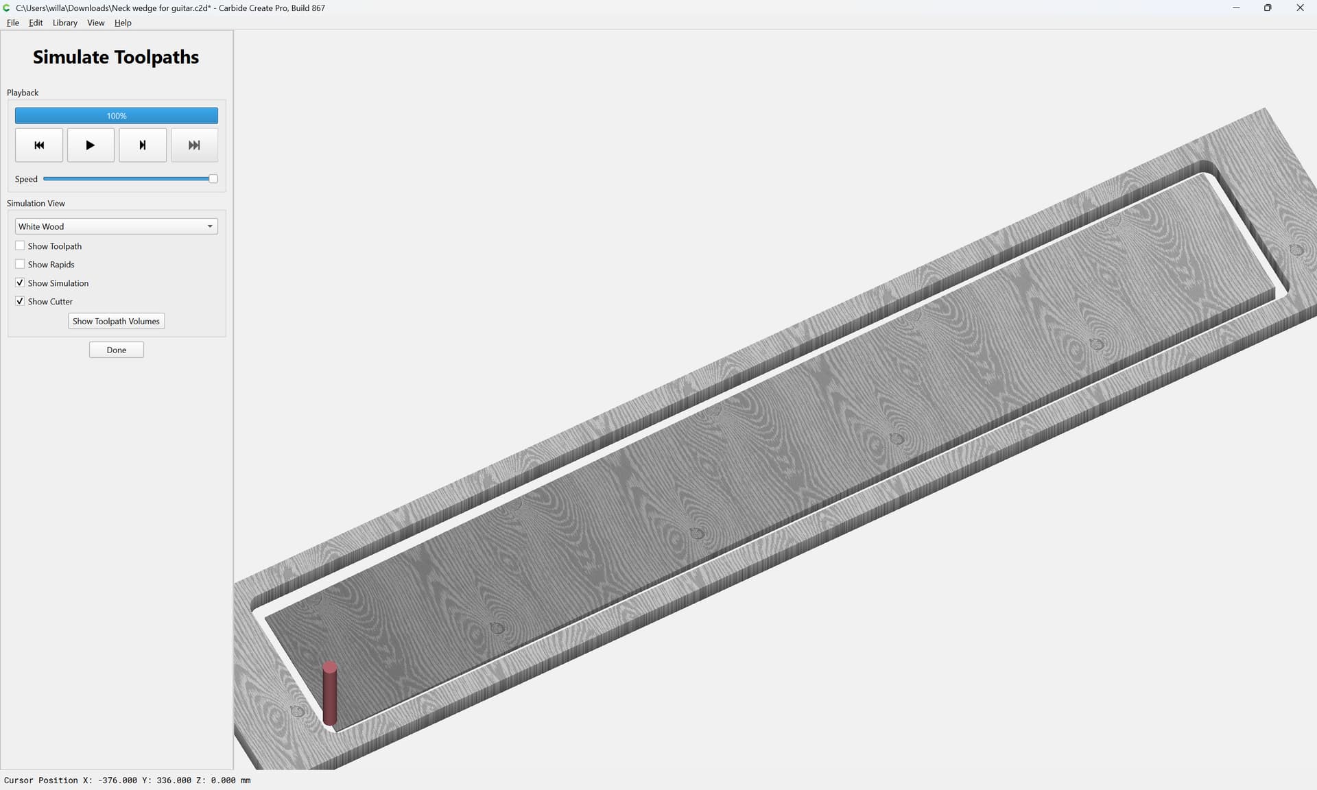
Attached as a v8 file.
Neck wedge for guitar_v8.c2d (120 KB)
2 Likes
We’d been trying to figure out the UI for a while, and defining angles seemed awkward. The drawing you sent it was the “ah-ha” to define a plane with three points directly. When we went back and looked at the other requests we’d gotten over time, that was the easiest approach for them as well.
Which is a long way to say, “thanks for the drawing.”
2 Likes