Cuts Off by 1mm?

That’s sort of what I have right now. The tape says 351, the shapeoko says 350. The 2 don’t agree. My comment about getting a 2nd device to measure would be to see if the 2nd agrees with the tape or the shapeoko :slight_smile:

I’ll check the belt calibration as you suggested.

The biggest issue really however, is things not aligning on the flip. Even with indexing brackets and using a touch probe, it was off.

My agenda for today is:

  1. check the calibration.
  2. sketch up a better explanation of what I mean by it being off on the flip
  3. cut a smaller part, this one will be small enough that I can use my calipers on
1 Like

Keeping alignment on multi-sided machining is one of the harder things to get right and can be really frustrating to learn. I did a lot of sanding to flatten out < 0.5mm offsets in two sided cuts early on.

This thread has some good examples of how people do it (enl_public has some strong workholding fu)

Many of the folks who seem to get it right put locating pins into the stock before the first op and then use those to locate the part when inverting, that or a machined jig which holds the part in each orientation. Otherwise you are relying on your measurement of the part width (and height) agreeing exactly with the machine’s measurement to get the workpiece zero in the correct place for the second op if you’re measuring off, say, the bottom left corner. There’s a few posts about this in the gallery

Try not to re-zero for the workpiece whenever possible as that’s a source of possible error, most of the good workpiece manipulation tricks work by cancelling out errors.

The locating pins trick works because they get drilled into the stock at whatever the machine thinks that distance should be so, as long as you don’t mess with the machine between cuts, those distances match up when you flip the part.

I’m slowly switching to using the spoilboard as my zero instead of the top of the stock and learning to use an edge finder properly to zero in places the C3D block can’t do, like lower right corner.

1 Like

A quick update. I used the method by MikeP as mentioned and my steps using a 6" caliper and 90mm of travel are almost spot on.

$101=40 89.94
$100=40 90.00

I upped my $101=40.027 and that gave me a 89.99/90.00

So, for my 351mm measurements, it’s either something strange with my toolpaths, or more than likely just a crappy tape measure. I’ll post back when I cut something smaller today.

2 Likes

Accuracy is not equal to the best 2 out of 3! :smiley:

I didn’t use pins, “technically”.

After I cut the plate down to 350mm and before I moved the plate, I attached 2 4" mending plates to the mdf wasteboard and I butted them against the top and one side of the plate. I then removed the plate, flipped it and made sure it butted up against those plates.

I then re-zerod using the Carbide touch probe. Maybe I didn’t need to re-zero. The first time I did this, I didn’t use any pins or anything. I thought my first failure was because when I flipped it, I didn’t get it parallel/square to the X/Y axis.

I am using the double sided cnc tape for holding down the workpiece. It is solid enough that if I lift on the piece straight up it’ll start to lift the machine up.

I’ll send a picture of the bottom of the touch probe to support as requested.

I forgot to add, I am using Carbide Motion, build 513, with an HDZ with SuckIt ears. Not sure if that matters, but thought it would be good document that.

Yup, but better than 1 out of 2! :laughing:

Not if the “1” was the accurate one. :smiley:

That can be a real time sink trying to get the workpiece square to the machine. One way to help with that is, once you have your machine squared up and trammed properly you can create a CAM job to put holes in your spoilboard for locating pins that are square with the machine, then you just stick in the pins you need to help locate the piece before cutting (and occasionally remember to take them out before running a cutter through them on an edge chamfer…).

5 Likes

I still haven’t cut a smaller item yet, but regarding my issue on “the flip” and re-zeroing, I found this thread:

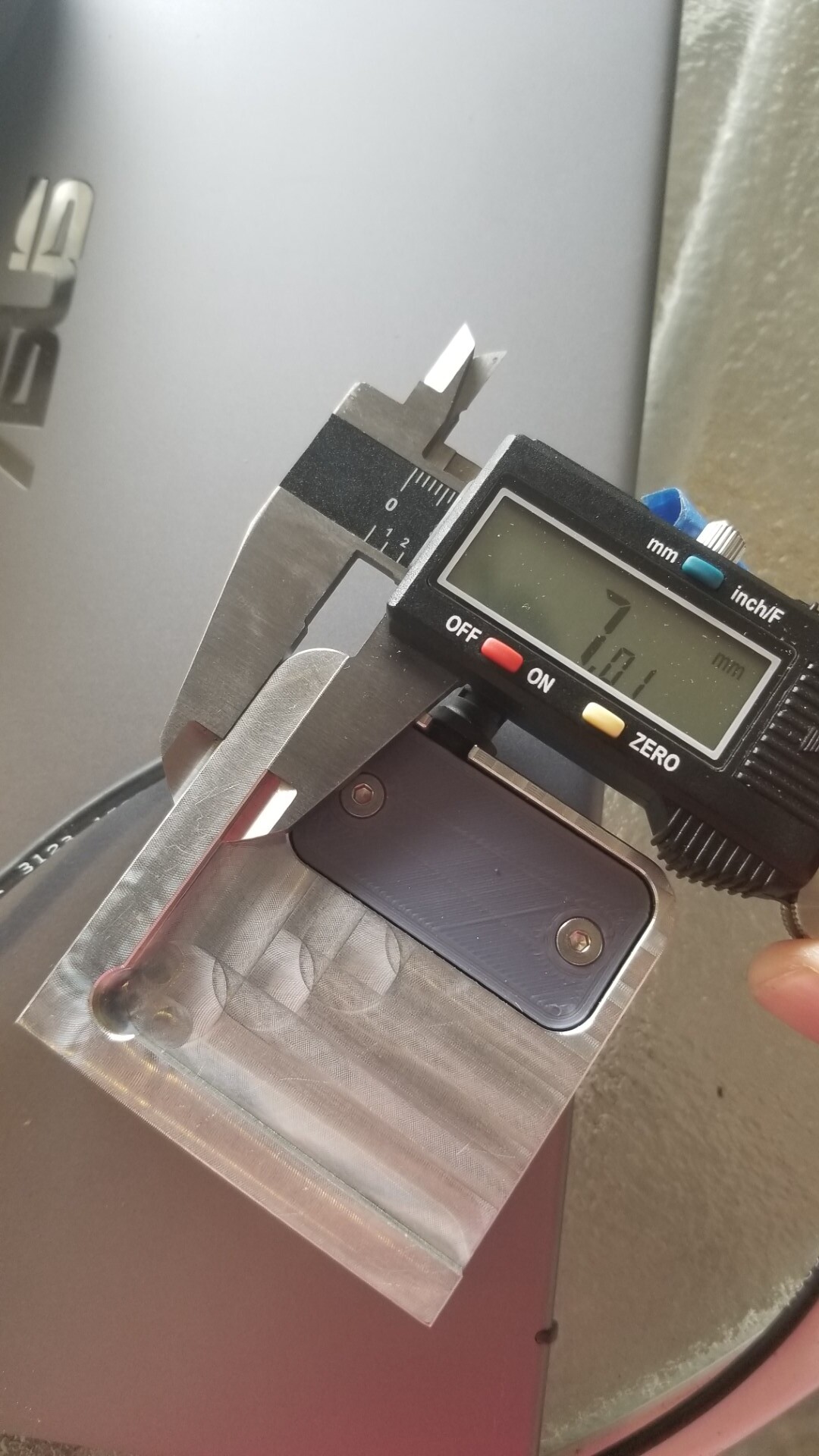
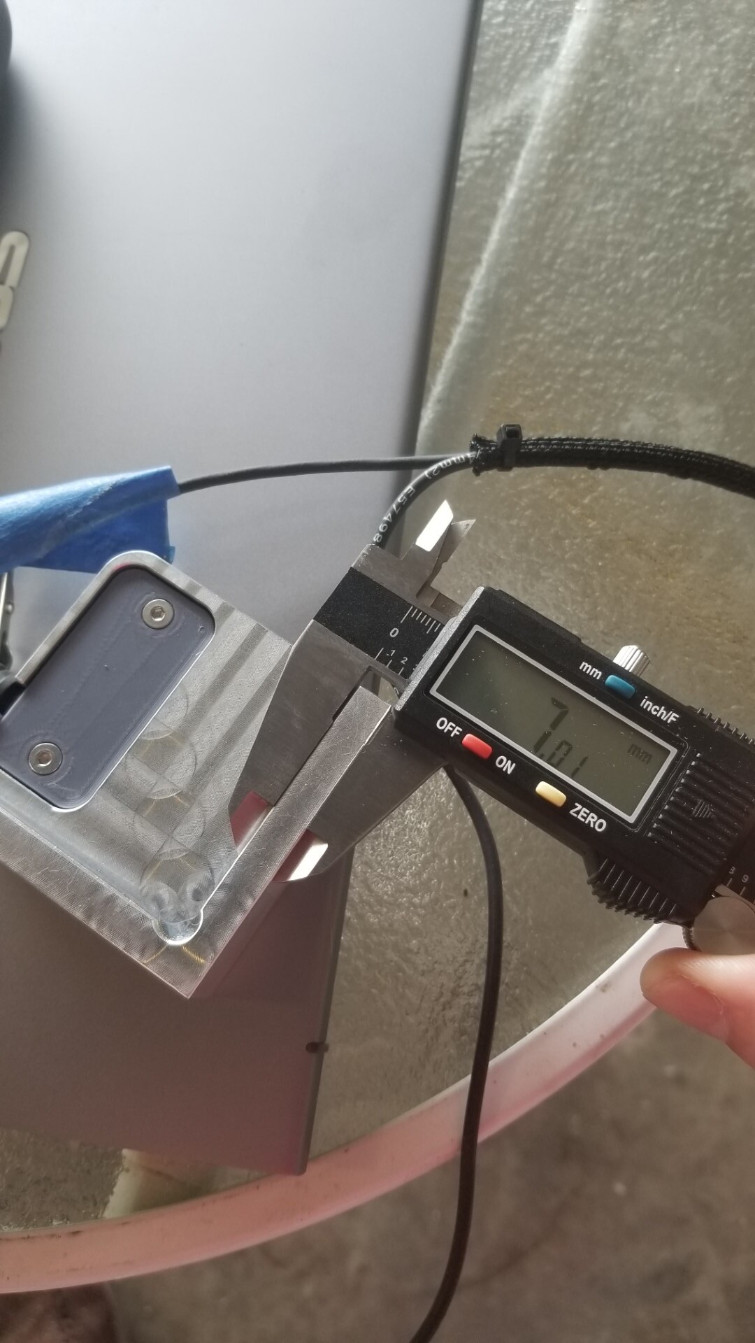
I never saw a resolution. I did send an email to support with the requested pictures. I figured I’d attach them here as well.


Looks consistent to me. Assuming it is suppose to be 7mm.

I haven’t come across any glaring hardware issues, so the more I think about it, the more it has to be operator error. I’ll keep looking and adding information to the thread as I find it.

3 Likes

Here’s the dimensions of mine when I measured it.

Did you try zero-ing with the 1/4 inch 201 cutter and then swapping out for a V bit and manually checking whether it was over the corner of the stock?

Also, are you using the 201 cutter or some other 1/4 inch cutter? I ask because some of the Yonico 1/4 inch cutters I use are low helix 2 flute

and you need to make sure these are at the right angle to contact the edges of the block at their outer dimension. The 201 has 3 flutes and a much steeper helix so it needs limited overlap to ensure the cutter perimiter hits the block.

4 Likes

Yes, I swapped over to the 201Z when I zeroed. I think the first time I used something else, which is why I made sure to use the 201 this time.

Looks like our dimensions on the touch probe matches.

I’m leaning towards cutting a better waste board, including holes for alignment pins. I’ll leave the board on and not remove it to make sure the alignment pin holes are square to the gantry.

I think I just need to play with it a bit more to get either more data points, or more experience.

2 Likes

It can add a little extra to the work flow, but ever since @WillAdams mentioned probing with a gage pin, I’ve adopted that method. It keeps things consistent; always clean, doesn’t have any cutting edges/tips that wear, safe to handle, and it’s cheap.

7 Likes

Ok, so I cut something smaller that I could get some calipers on.
https://a360.co/30cfY0c

It should be 120x120mm across the centers.

Across the X axis, it is120.35mm and across the Y axis it is 120.65mm. If you see from a previous post, I did adjust the Y steps from 40 to 40.027, but everything measured good via the MikeP caliper test.

This time I used a single flute 278Z because I think I’ve fubar’d both my 201Zs.

Could it “just” be deflection this time ?
(I don’t have access to Fusion right now so I can’t check your toolpaths to see if you used a separate finishing pass). It could be interesting to try that same cut in the softest material you can find and check whether it comes out more precise.

It would also be interesting to cut pieces of various dimensions to figure out if the error is a constant offset (likely deflection or a zeroing inaccurary) or a linear error (likely belt calibration).

3 Likes

It could indeed be the finishing passes. I was attempting to do 2 passes, full depth. These 2 items, the original 350mm and the 120mm item are the first I’ve played with finishing passes.

From the 120mm item: (With a #278 bit, 1/4" single flute ZRN endmill, 18k RPM)

Before I cut out the 120mm part, I did ensure my steps were good. For something unrelated, I’m going to change out some v-wheels, so I’ll be re-tensioning belts. I’ll be sure to check my steps again afterwards.

Edit: The 350mm part was in 9.5mm of aluminum and the 120mm part was in 6.35mm aluminum. I’m wondering if the step over in the finishing pass is way too much? It was throwing some good chips and the router didn’t sound like it was bogged down.

2 Likes

I guess 0.6mm stepover may be a little too much for the last pass, the router would not struggle but the machine could still deflect a bit (you are 0.35mm off so that’s only 0.175mm deflection on each side). The only way to tell as usual is to experiment (either redo this cut at lower stepover in aluminium, or rerun the same cut in something very soft)

3 Likes

Thanks. I didn’t even consider the stepover until you mentioned it. I’ll probably give it a go and see what happens.

I love the videos Winston makes for aluminum feed and speeds, I just wish he included some information on finishing passes. I know it will (like everything CAM I’m learning) depend on a lot of factors, but anything would be nice.

Do you have a recommended feed/speed and stepover for a finishing pass, at least a recommended starting point?

I tend to use 0.25mm stock to leave and let the finishing pass shave that off. Ideally push the feedrate to compensate for chip thinning at that very small stepover but if you are not familiar with that, keep the same feedrate you use for the rest of the cut as a starting point, it should work fine.

3 Likes

One good way to figure out what your roughing and finishing stepovers are really up to, I’ve done this on plywood, particularly when changing bit to compression cutter for final full depth passes and I’m trying to get close joint clearances;

  • Run a roughing job with Stock to Leave, use the roughing passes / multiple depths etc.
  • Then run a finishing job with Multiple Finishing passes and the smaller stepovers.
  • Finally, run the finishing job (derive new operation is the fastest way to get this) with just the finishing pass.

Measurements during those job fragments;

  • Measure after the last roughing cut, read some known dimensions off the Fusion model and measure with a caliper, you can figure out what the dimensions should be from the stock to leave
  • Measure again after the last finishing stepover, same measurements, these are lower cutting load and should be lower deflection.
  • Measure again after the repeat finishing cut, the difference here is the “spring pass” or deflection you saw in the last finishing stepover.

I frequently find that just listening to the repeat finishing pass, even when it’s just part of one finishing toolpath tells me how heavy the engagement is.

HTH

3 Likes

This topic was automatically closed 30 days after the last reply. New replies are no longer allowed.