This is the 2nd time this happened. I’ve ensured everything is square, belts are tight.
I have a piece of aluminum that is about 360x360x9.5mm that I am attempting to cut down to 350x350mm.
The first time I used a 1/4" single flute endmill, the 2nd time, a 1/4" 3 flute endmill. After it is cut, it measures 351mm on my tape. I thought that maybe my tape is just crap, so I flipped it to cut on the bottom side.
Both the top and the bottom have a light chamfer. After the first time it failed, I thought maybe I didn’t have it square to the machine when I flipped it. This time, before I flipped it, I screwed down some metal strips on the top and side to serve as “indexing pins” so to speak.
I flipped it, re-zero’d with the touch probe (since it is now cut out of the original stock). The chamfer toolpath started at around the 3 o’clock position. It was cutting just fine until it made the turn to cut the bottom, (that is, along the X axis at the front of the machine) when I noticed the bit wasn’t even touching the machine, it was off by about 1mm.
I immediately stopped the job because the first time I tried it, I let it go and it tried to make up the 1mm by cutting 1mm into the back side.
It is like the touch probe is “off”. I used a 1/8" endmill to probe (102-Z).
I cannot verify the plate is actually 351mm after the cut. The tape says it is, but I have nothing to back that up. So, I’m not sure if the issues are one and the same.
Kind of shooting from the hip without looking at the file but do you have ‘Stock to leave’ checked on one of those toolpaths? The default is usually 0.5mm and with a squarish toolpath that would add up to your 1mm
Please make a simple test project for this and cut it and if it too is off, send a photo of the underside of your BitZero and the test cut in a caliper in to us at support@carbide3d.com
I double checked it and it is off. That was the first thing I thought about as well. I probably need to get a secondary measuring device just to make sure my tape isn’t off.
I’ll try to come up with something later today. I’ll have to cut something smaller, but that might be better because I can then use my calipers to check the size.
So like Will says, a simple piece is the way to go.
MikeP has a post on how to use a set of calipers to calibrate belt steps.
I used that and also then on my XXL used a sharp V bit and a magnifier to check the travel over 600mm. The bigger the distance you jog the better as you make the backlash error smaller.
When doing your X, Y calibration if you’re measuring or using the caliper, only jog in one direction, e.g. jog right to the “zero” of your measurement and then keep jogging right to your next measurement or you’ll end up including the backlash in your distance measurement, over small distances that gets really confusing.
Not sure what size machine you’re using but the backlash is a lot more of a problem on the longer axes of the XL and XXL.
All measuring devices have an error, the only difference is how large that error is and whether the error is consistent.
If you use the same tape for all measurements and it’s consistent, e.g. one mm on the tape is close enough to 1/1000th of a metre then that’s your measurement. The confusion comes when using multiple measuring devices which may not agree, or where a device is inconsistent within it’s own measurements.
That’s sort of what I have right now. The tape says 351, the shapeoko says 350. The 2 don’t agree. My comment about getting a 2nd device to measure would be to see if the 2nd agrees with the tape or the shapeoko
I’ll check the belt calibration as you suggested.
The biggest issue really however, is things not aligning on the flip. Even with indexing brackets and using a touch probe, it was off.
My agenda for today is:
check the calibration.
sketch up a better explanation of what I mean by it being off on the flip
cut a smaller part, this one will be small enough that I can use my calipers on
Keeping alignment on multi-sided machining is one of the harder things to get right and can be really frustrating to learn. I did a lot of sanding to flatten out < 0.5mm offsets in two sided cuts early on.
This thread has some good examples of how people do it (enl_public has some strong workholding fu)
Many of the folks who seem to get it right put locating pins into the stock before the first op and then use those to locate the part when inverting, that or a machined jig which holds the part in each orientation. Otherwise you are relying on your measurement of the part width (and height) agreeing exactly with the machine’s measurement to get the workpiece zero in the correct place for the second op if you’re measuring off, say, the bottom left corner. There’s a few posts about this in the gallery
Try not to re-zero for the workpiece whenever possible as that’s a source of possible error, most of the good workpiece manipulation tricks work by cancelling out errors.
The locating pins trick works because they get drilled into the stock at whatever the machine thinks that distance should be so, as long as you don’t mess with the machine between cuts, those distances match up when you flip the part.
I’m slowly switching to using the spoilboard as my zero instead of the top of the stock and learning to use an edge finder properly to zero in places the C3D block can’t do, like lower right corner.
A quick update. I used the method by MikeP as mentioned and my steps using a 6" caliper and 90mm of travel are almost spot on.
$101=40 89.94
$100=40 90.00
I upped my $101=40.027 and that gave me a 89.99/90.00
So, for my 351mm measurements, it’s either something strange with my toolpaths, or more than likely just a crappy tape measure. I’ll post back when I cut something smaller today.
After I cut the plate down to 350mm and before I moved the plate, I attached 2 4" mending plates to the mdf wasteboard and I butted them against the top and one side of the plate. I then removed the plate, flipped it and made sure it butted up against those plates.
I then re-zerod using the Carbide touch probe. Maybe I didn’t need to re-zero. The first time I did this, I didn’t use any pins or anything. I thought my first failure was because when I flipped it, I didn’t get it parallel/square to the X/Y axis.
I am using the double sided cnc tape for holding down the workpiece. It is solid enough that if I lift on the piece straight up it’ll start to lift the machine up.
I’ll send a picture of the bottom of the touch probe to support as requested.
I forgot to add, I am using Carbide Motion, build 513, with an HDZ with SuckIt ears. Not sure if that matters, but thought it would be good document that.
That can be a real time sink trying to get the workpiece square to the machine. One way to help with that is, once you have your machine squared up and trammed properly you can create a CAM job to put holes in your spoilboard for locating pins that are square with the machine, then you just stick in the pins you need to help locate the piece before cutting (and occasionally remember to take them out before running a cutter through them on an edge chamfer…).
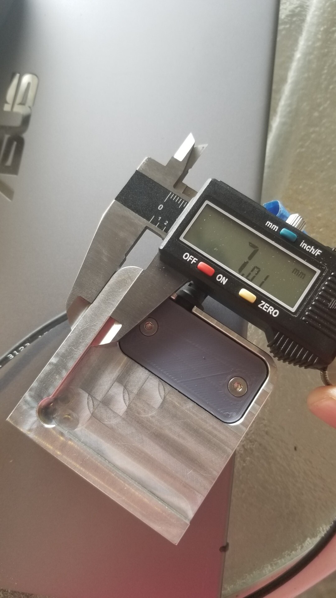
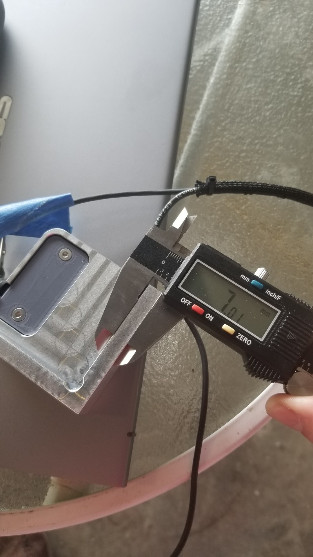
Looks consistent to me. Assuming it is suppose to be 7mm.
I haven’t come across any glaring hardware issues, so the more I think about it, the more it has to be operator error. I’ll keep looking and adding information to the thread as I find it.
and you need to make sure these are at the right angle to contact the edges of the block at their outer dimension. The 201 has 3 flutes and a much steeper helix so it needs limited overlap to ensure the cutter perimiter hits the block.
Yes, I swapped over to the 201Z when I zeroed. I think the first time I used something else, which is why I made sure to use the 201 this time.
Looks like our dimensions on the touch probe matches.
I’m leaning towards cutting a better waste board, including holes for alignment pins. I’ll leave the board on and not remove it to make sure the alignment pin holes are square to the gantry.
I think I just need to play with it a bit more to get either more data points, or more experience.