that⠀⠀⠀⠀⠀⠀⠀⠀⠀⠀⠀⠀⠀⠀⠀⠀
I’d vote for plug-ins. Being able to specify which area the plug-in applies to (pocketing, v carve, etc) superficially appears to be tricky, but I’m retired and quite happily forgetting those kinds of details 
1 Like
plugins can be hard, you need to have some sort of safe data exchange model between app and plugin, and that means you cannot just change your internals anymore as easily… I can see why the C3D folks hesitate on that.
1 Like
I would be fine with the overhead of writing out a file and interacting with the file, then re-loading it.
Maybe they can be convinced to do an NDA and let you work some magic on CC or perhaps both of you can come to an agreement to adapt your code into CC with something like a portions contributed by credit
There’s been a recent bit published on this sort of thing:
and see the video linked in the discussion.
1 Like
I saw that before… the title was more interesting than the content, meaning, there was a “hey look in an FFT you can see something” but not a “and this is what it means”
but yes I put using audio as an input on my (getting longer) TODO list
1 Like
Today I had some ruined pieces as part of trying to get pictures of the difference between CC, my tool with and without finishing pass… the CC cut sounded aweful in one corner and ended up with damage there, while my tool ended up getting the piece loose from the workholding. Woops.
So I did an emergency implementation towards more adaptive-style behavior, by slowing down once you’re within half a tool diameter of a corner… real adaptive is next on my todo list still.
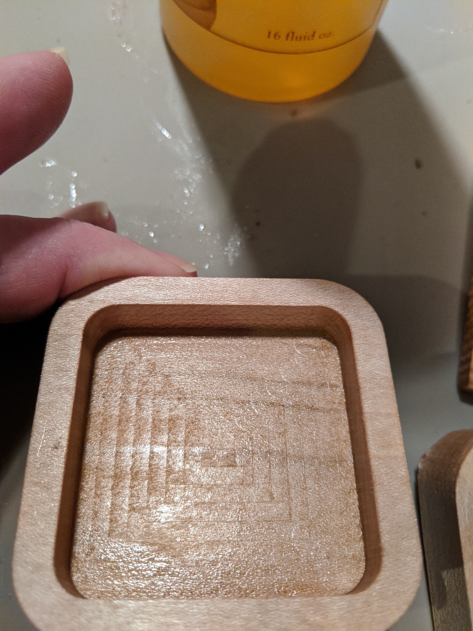
A second set of cuts done (results below) and I must say that the CC cut sounded much worse, in corners and in the cutout (exactly where the bit goes down to the next ring) there were little bits where you could hear that suddenly the forces are higher… cringing kind of sound.
Spiral based cutout (as the tool has) is just one smooth cut… no bad sounds anywhere. And the slowing down for corners took the bad sounds out of pocketing.
Anyway, results with pictures:
C2D file including toolpaths:testcut-square.c2d (52.0 KB)
Which is exported as SVG as well for my tool: 
The results:
CC gcode file:
testcut2-square-cc.nc (65.1 KB)
CC inside pocket:
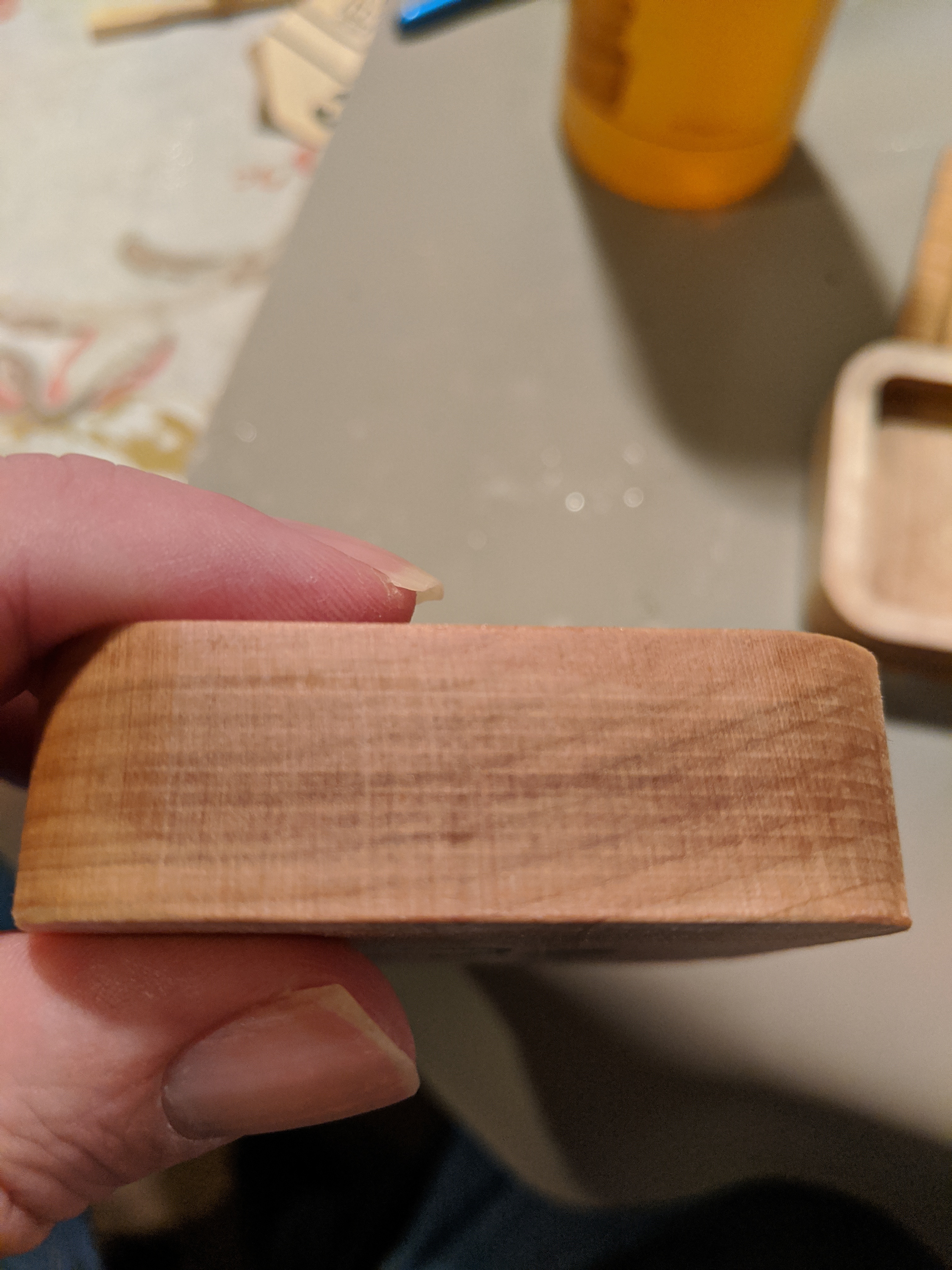
CC side wall
New tool, inside pocket
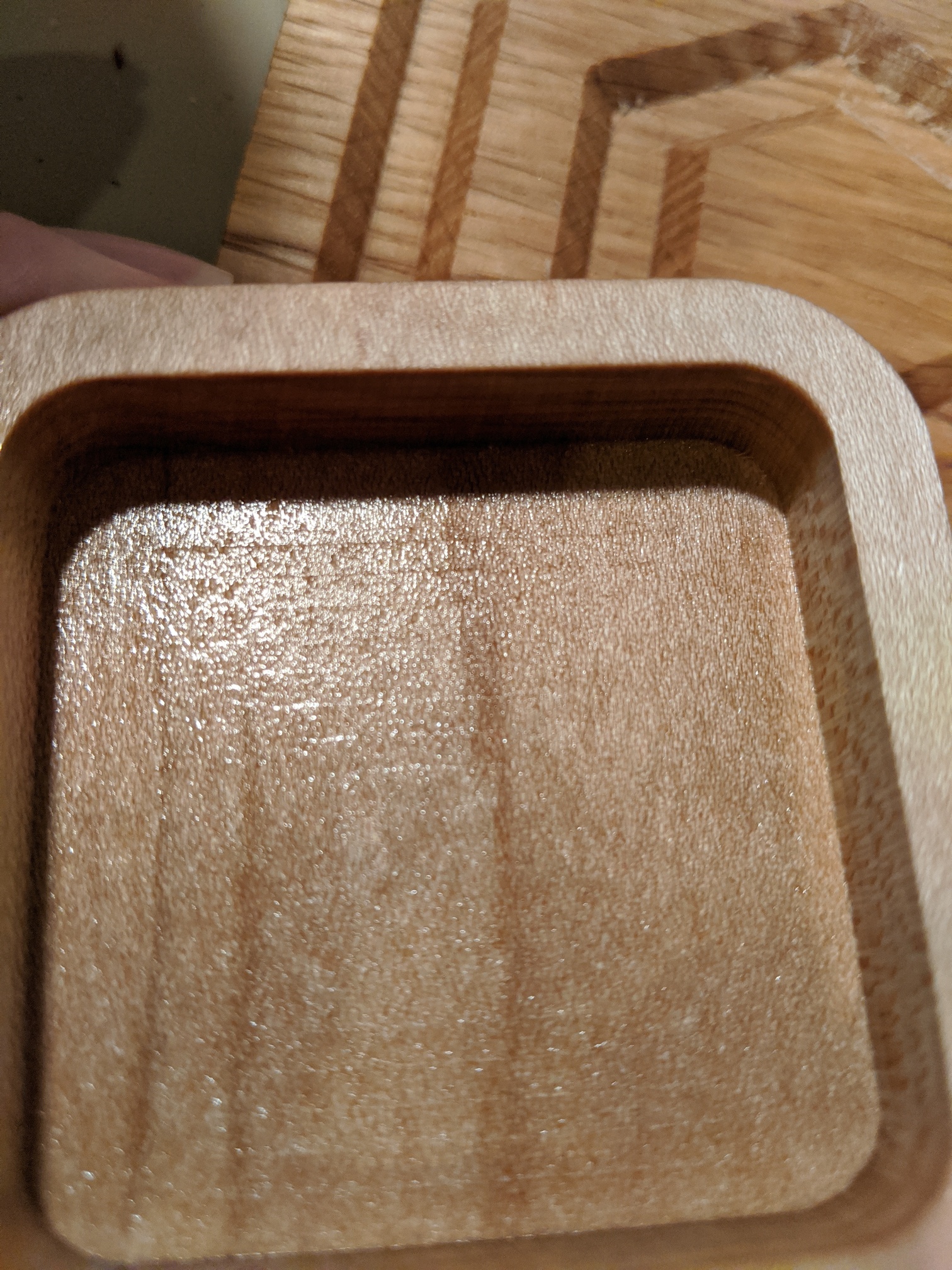
New tool, side wall:
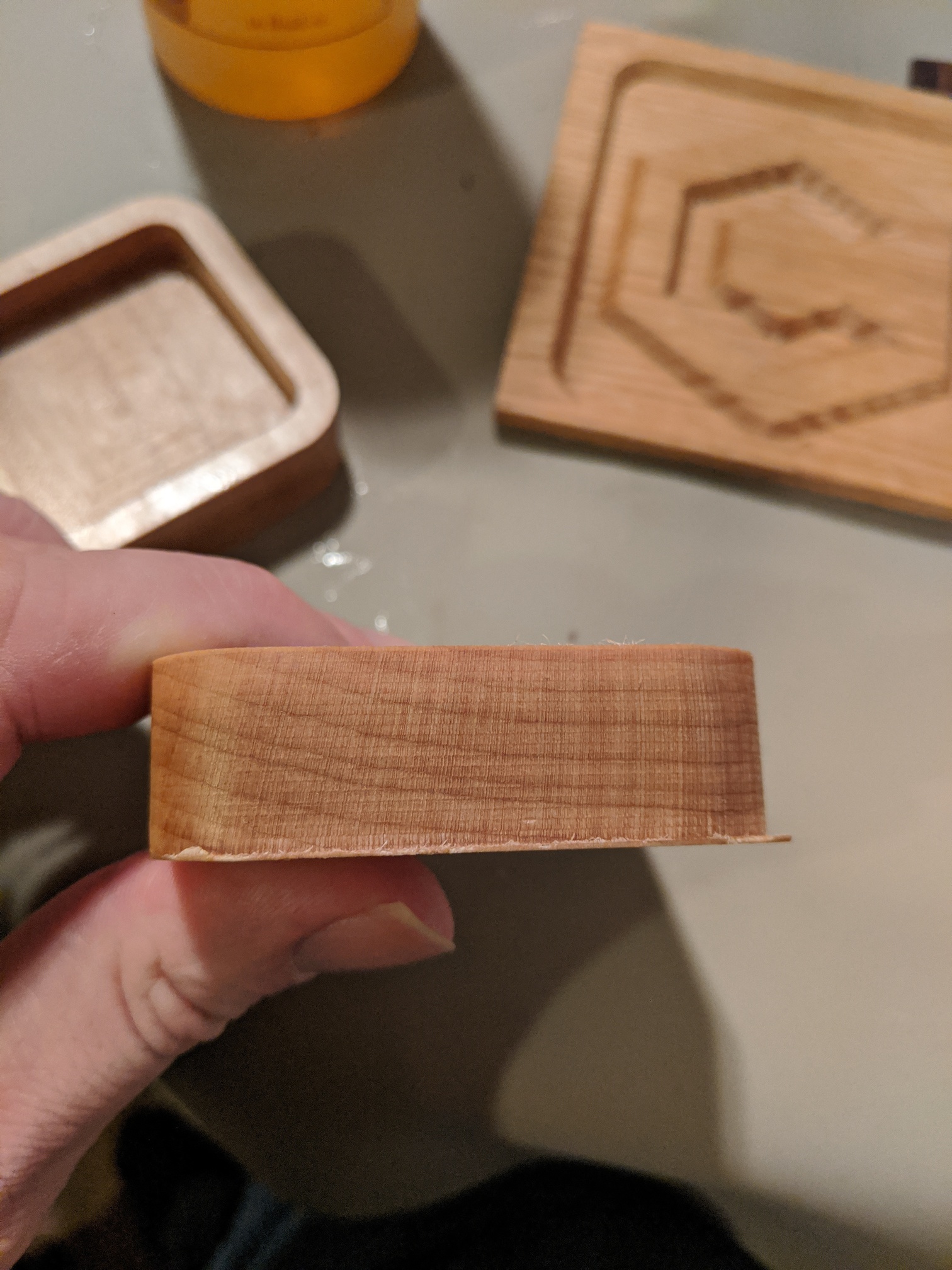
Clearly I had set the stock-to-leave to be too small (0.1mm), will play with that more… but the result is clearly smoother as a result of the finishing pass.
(all 1/4" bit, 0.05" DOC with 60IPS feed rate)
1 Like
@WillAdams Thanks for posting that! A high quality, reasonably priced (for ATC) HF spindle actually made in the US! Also, I’ve been using Audacity for years and never realized that it had a spectrogram display option!
this sooo is asking for some machine learning thing that you can train bad sounds (chatter and probably other things) that gives you a score/rating/diagnostic.
but that’s obviously not a 5 minute task
1 Like
Or human operator training augmented with knowledge, quiet spindles, and cutting power monitoring.
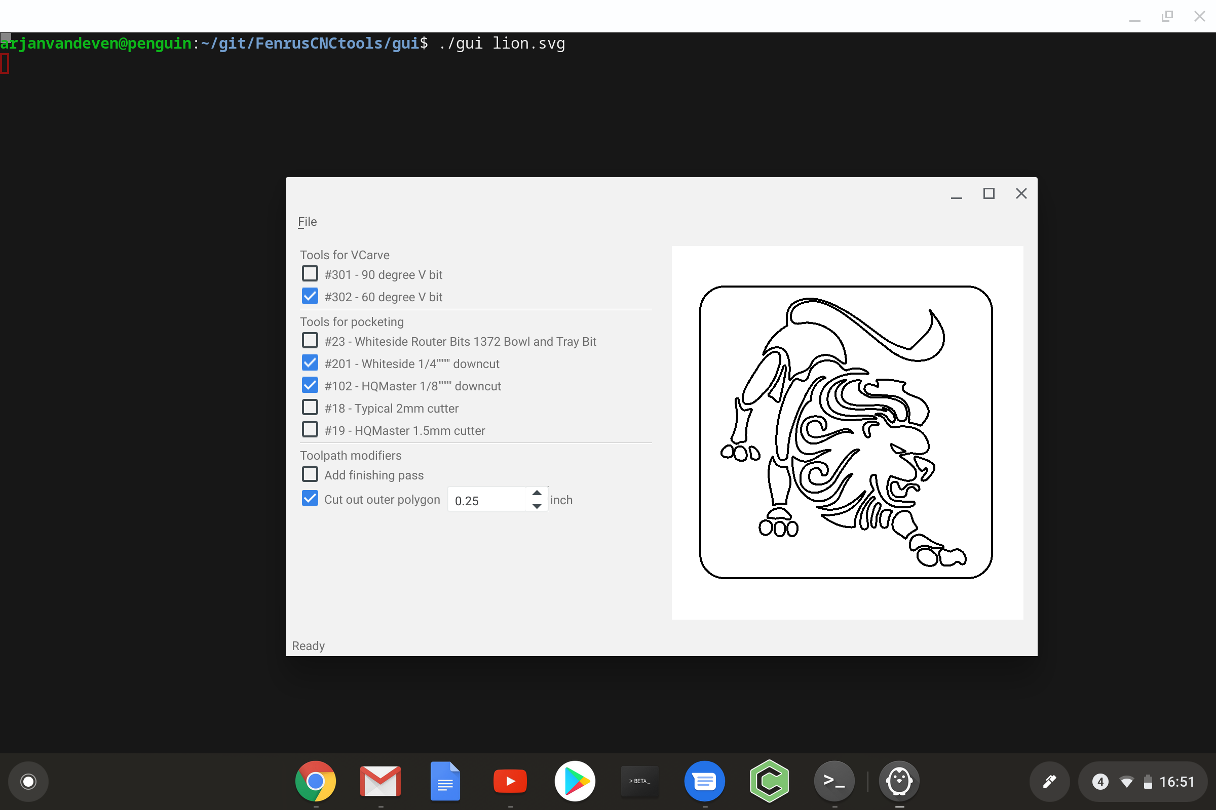
I realized that in order to do what Will would like (enter depths for parts of lines/splines) I need to build a GUI… which really is not my kind of thing and something I haven’t done in over a decade
but small steps
2 Likes
For my part, I’m caving and going entirely the opposite direction and looking into just hand-coding in G-Code.
if you’re not scared of an editor and text files… the tool I’m building has a gcode abstraction so you can just do “go from XYZ_1to XYZ_2” while it takes care of travel/retract/etc inbetween points.
one level up in the datastructures it’ll also do the right thing for max depth of cut and turn things into multiple passes. (and since yesterday, slow down before corners … )
the hardest part for what you want is the input side… how do you express it
(while I’m writing that a simple CSV file could likely do that… that’d be quick to build)
Yeah, that’s the problem — I’ve been:
- drawing things up by hand in Freehand
- noting the location of points in the inspector palette
- switching to NCplot or CAMotics and pasting the numbers in
- editing in the appropriate G-Code commands
For straight lines it’s pretty easy (and one could express that in a CSV quite simply) — the problem is, I want 3-dimensional curves (well arcs — I’ve been looking at the math for converting Bézier curves into arcs and that will have to wait a while and I’ll probably never get to it).
I’m considering an interim approach where I draw up and do the CAM for each element individually, then stitch them together in G-Code (or CAMotics — I think one can string together multiple files in it) — really surprised there isn’t a CAM tool which will let one cut 3-dimensional things out using a V endmill (or is there and I missed it?).
Got an example of what you’re trying to do?
It’s various ideas for joinery — I’ve posted OpenSCAD renderings of them here in the past I think — or just the relieved finger joints for the magazine rack — it really shouldn’t be necessary to create two additional paths for each finger in order to get the desired result.
you could do the beziers in the csv as well something like
1, 1, 1,
1, 4, 1,
1, 5, 2, Q
2, 6, 3,
where the Q point is the quadratic bezier inbetween point. 2 Cs for cubic curves… also not a big deal.
for now I would end up making those discrete internally (but with small steps) since I’m quite scared still of G code arcs. (I needed this anyway for SVG parsing… you’d sort of end up specifying a 3D SVG
1 Like
ok this is now working… wasn’t all THAT complicated it seems
the following CSV
4 4 -0.4
4 8 -0.5
8 8 -0.3
8 5 -0.2 7 5.5 -0.1
4 4 -0.4
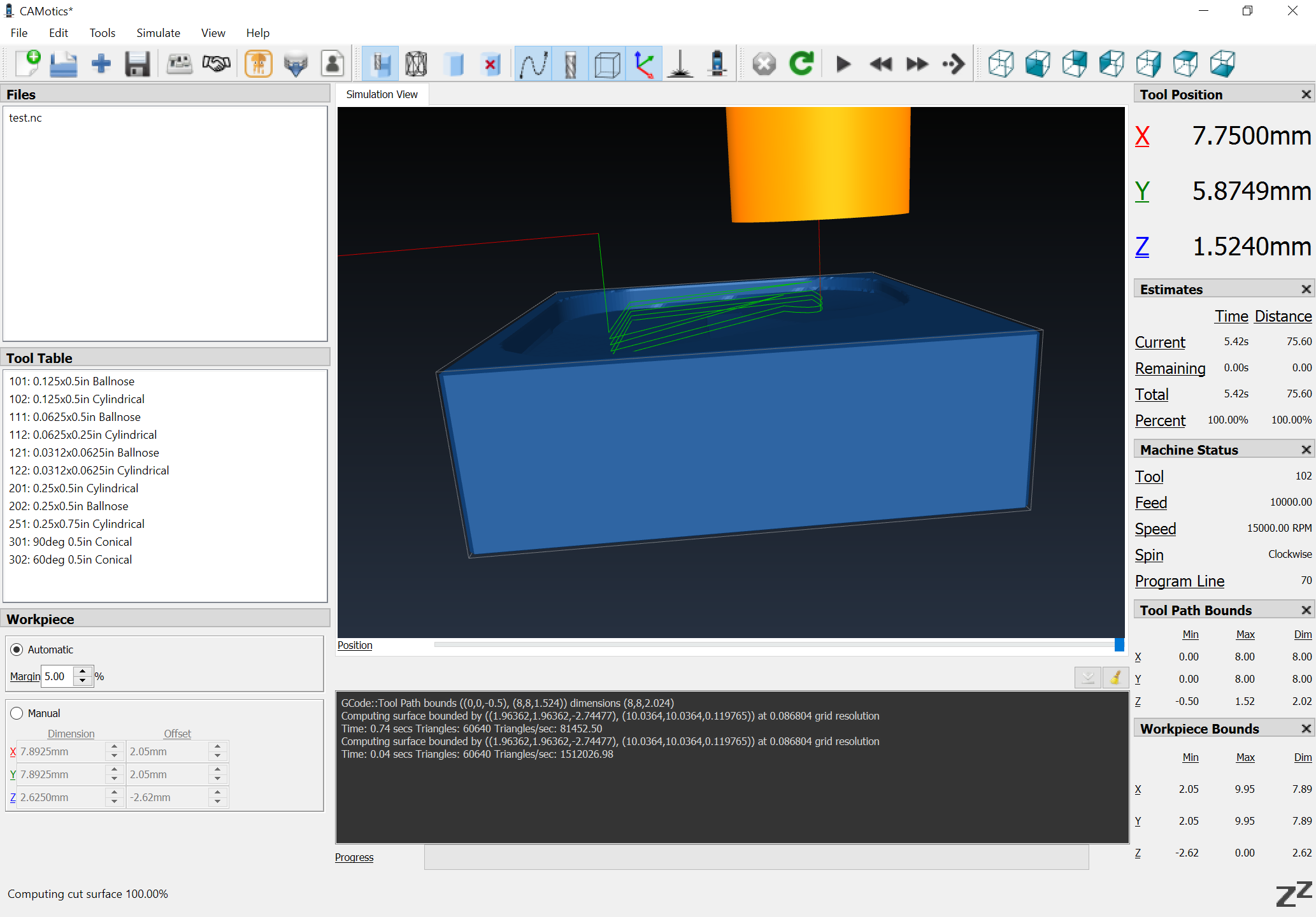
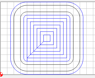
gives as toolpath (with bit 102)
./toolpath -t 102 test.csv
test.nc (1.4 KB)
a 2nd example:
4 4 -0.4
4 8 -0.5
8 8 -0.2
8 5 -0.3 6 4 -0.5
6 9 -0.4
gives test2.nc (3.0 KB)
normal points are just given as 3 values, the 6 (or 9) value lines are beziers
the file can be comma or space separated, either works
(for the example I forced max depth of cut of tool 102 to 0.1mm so you can see multiple paths)