When I first got my 3XL almost a year ago… the first few months I lost several pieces that came loose (and thus also had to rebuild the Z carriage several times) due to the following pattern that Carbide Create uses for its toolpaths:
The little paths where the cutter goes from one inner path to the next one is done at full speed, but unlike the normal part of the path where there is 50% stepover, these have full cutter engagement, and in addition, at the edge of the work piece the forces get multiplied due to the long distance from the center of the work (basic mechanics with an arm)
Over time I learned to reduce my F&S just to avoid this, but it has been bugging me ever since.
In this forum several times it has come up that you can estimate cutting forces by measuring the current to the router, so I got a cheap bluetooth enabled current clamp from Amazon, and made a simple design to see if I could measure these little lines, and then take it from there.
Plan was: Create a computer program that reads an SVG from Carbide Create, calculate toolpaths that match what Carbide Create generates, write gcode where those little “cross path” lines run at a reduced F&S and measure the current again.
This is where I got a bit derailed, since I’m still fighting how to get the CSV file from the clamp off my ipad without getting heaps of malware on my PC.
Anyway I made a simple Carbide 3D like logo in Carbide Create (filesnf-carbide-test.c2d (24.4 KB) ) to be cut with a 1/8" bit on a few 4"x4" scraps of oak that I have sitting around.
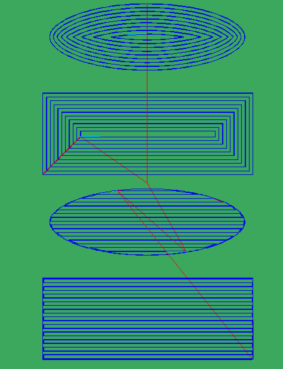
The toolpath for the design looks like this:

And I noticed something that I had hit before, where there seems to be a pretty large gap between toolpaths in part of the design… effectively there’s a double full cutter engagement happening there. In the past when I had this, I either ended up with “fuzz” on the wood, or even a small ridge left standing.
When I cut the gcode from Carbide Create (file:snf-carbide-test-cc.nc (39.3 KB) ) I indeed got my surprise:
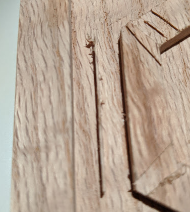
and of course there where the usual tool marks:
I used the F&S from @wmoy’s video (https://www.youtube.com/watch?v=cjoNGACBkks ): 0.045" depth of cut, feedrate of 50ipm (figured that oak was somewhere between soft and hard), but ran Carbide Motion at 120% for all experiments here.
When I filed a ticket with the support folks earlier this year about the little ridges, @robgrz came back saying that they knew about these but that it is a very hard problem to resolve… triggering a personal character weakness in me: I wondered “How hard can it be”… the 5 most dangerous words in computer science.
Well, since I was fighting my Ipad to let the current measurements leave the device, I went to plan B: Create a computer program that read the SVG output of Carbide Create, make toolpaths and see how hard it really is to fix these issues.
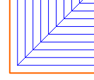
So the basic toolpaths my program creates are eerily similar to those of CC:

which was good news for me. (the red paths get cut in the opposite cut direction, just like CC does)
Even the “void where the ridge happens” ended up being replicated.
Next step: fix the ridges.
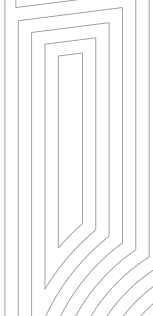
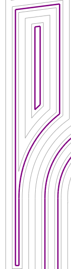
Turns out this was actually surprisingly simple. The process you use to create these toolpaths ends up with a “center line” (‘interior skeleton’ in math terms) and that center line is exactly all the places where I would normally get ridges or fuzz in my designs. The tool now also adds a specific toolpath just for this, and will cut this toolpath first (at a reduced speed since it’ll be 100% with full cutter engagement).
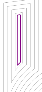
Basically this operation adds the pink colored path in the paths below:

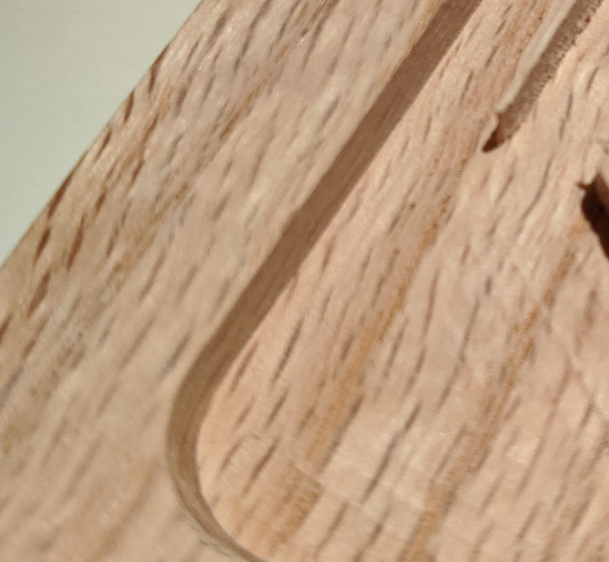
I then turned this into gcode (file: carbide-with-slotpass.nc (41.4 KB) and cut this out of another piece of oak:
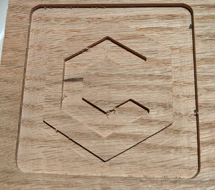
and as you can see, the ridges and any fuzz are gone, but the toolmarks are still visible.
I always wanted a finishing pass option in Carbide Create, so I figured I should build one of those as well given that I had gotten this far already.
In the finishing pass, the deepest cut layer is only 0.2mm thick and a programmed in a reduced stepover. In addition, all layers above this layer have a small inset on the edges so that the final finishing pass takes away a little bit of material at the edges.
The resulting gcode file is here carbide-with-finishing.nc (69.7 KB)
and it looks great, the toolmarks are basically gone:

What’s next:
- Trying to convince the Carbide 3D folks that this would be great to have in Carbide Create (I’m happy to provide implementation details if the C3D folks are interested)
- Consult the F&S experts on this forum what the best strategy is for slotting paths: Go half speed at full depth or go full speed at half depth (so far the easiest thing was half speed at full depth)
- Clean the code up a bit and put it on my github
- Try a few more complicated designs to see how the algorithms behave
- Figure out how to liberate the current measurement data from my ipad and analyze the actual reduction in force