do you mean to basically do an extra full stepover inset always?
(that’s… complicated a little bit in the math)
also normally CC will cut these from the inside towards the outside
do you mean to basically do an extra full stepover inset always?
(that’s… complicated a little bit in the math)
also normally CC will cut these from the inside towards the outside
Aren’t you proposing a way to pocket from the outside in rather than inside out as currently supported by CC and Vectric? Is the math harder than the alternatives? Is there some other downside of always doing an “extra full stepover inset”?
the code right now follows the inside-out, but… that’s just to copy what CC does. it’s more work (not much but still)
The way any of this is done is that the math is done outside in, and then the order is inverted when gcode is written. But it’s by no means fundamental … yet.
I’m about to play with adding a way to have a roughing tool and a finish tool (or multiple of each) in a way that you do relatively efficient rest machining, and once you do that, inside out likely makes the most sense (start with the largest bit, clean out the most then go to smaller and smaller bits for the details)
going to a full “overshoot” I will need to check if and how that can work; the perfect “just do a line through the middle” is easy, but that was the original “skeleton” approach… I have that coded but not sure the CC folks can deal with the complexity of it
btw just to be clear, I’m not trying to replace Carbide Create… I actually really like CC. I’ve been using it for the better part of a year now and have realized that with some small tweaks the resulting gcode could give better results, from the same input/everything else… and I decided to prototype how that would work (both because it’s fun and because I don’t want to ask for something that turns out to be impossible)
So far what I would like to see in Carbide Create’s gcode generation side

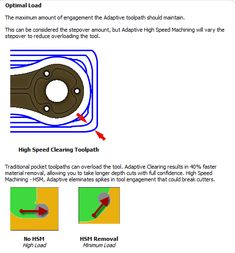
IMO, at least for rough pocketing, outside in makes the most sense because it prevents problematic cutter radial engagement angle increases during direction changes. This enables greater fixed depths of cut and feed rates for the stepover passes, as do HEM and adaptive clearing toolpaths/strategies.
For wood, it also enables the use of larger diameter straight cutters for cleaner cutting and lower forces.
fair enough… I’ll build both and play with it… of all the hard things, this isn’t it
just an update; implemented the option for outside in pocket toolpaths. Also added basic V carving support to the code. Next is a vcarve+normal tool combo where you set a max depth for the vcarve and do a pocketing operating for the deeper parts.
(once that is there it should be possible to layer on a inlay option where the single export file from carbide create gets turned into 2 gcode files, one for the inlay hole and one for the plug)
I also need to work on the remainder of cut quality stuff, but my XL is out of tram due to a collision between hdz and bitsetter and need to finish rebuilding it more or less since something is off and I don’t know what quite yet.
A “outside in” toolpath in gcode looks like this:
snf-test.nc (54.0 KB)
which visually looks like this (svg won’t have ordering obviously)

this is a basic test pattern where the roughing is done with #102 (1/8") shown as purple, and then the detail is carved with a 1.5mm bi shown as yellow
2020 prediction: @fenrus also implements adaptive clearing for fun, gets hired by Carbide 3D, CC becomes the industry standard for CAM, people applaud 
Very impressive progress, sir. I am following this thread with great interest, keep pushing those limits!
I have had the same type of challenges. since I am new to CNC I have made many mistakes that throw the machine out of adjustment and the machine is not really designed to be adjusted, especially by an amateur like me.
When the machine was new, it worked great and each mistake I have made has thrown it a bit out of adjustment, mostly in rotation around the x and y axes. even though these misalignments are small, the fact that I typically cut with very small bits (.06 and .03 most of the time) in wood multiplies the fuzz and leftover line effects. I am learning that the amount of torque placed on an adjustable wheel plus dust and buildup makes a difference and am getting ready to basically take the machine apart and put it back together so I can look at every little part that I have probably bonked a bit too much as I have learned how to use the machine.
I would pay a lot of money to have a small click adjuster on the axis to get it back to flat after I bonk it. When it was new and flat everything I made looked perfect and now everything needs touch up. I expect that once I set aside a weekend to take the machine apart and put it back together it will be perfect again but an adjuster seems to make more sense. NOTE to the management…
You could try and arduino with a current sensing board, they come in several ranges, and then send the data to a PC file or the serial monitor in real time. You might get a better idea of the forces on the machine if you measure the X,Y and Z forces as well but that might mean the use of strain gauges on the structure. A geeky display of realtime trends ( with LEDS, everything is better with multicolour LEDS) could start a new level of worry for users, I’m sure some of the higher end machines would do this.
Cheers
Mike
Wouldn’t just pocketing outside-in provide much of the advantages of HEM and adaptive clearing without the added complexity? Don’t those more complex strategies require dynamic control of feed rates? Does Carbide Motion even support that? Can you and/or others please point me to a good G Code viewer? ![]()
I don’t think they do, as far as I know the adaptive strategies are “only” based on keeping the tool engagement constant. Carbide Motion has no play in this anyway, as it only sends the generated G-code, whatever generated it?
For G-code viewing, I do my quick checks in this (for no other reason than it was the first I tried, and cannot be simpler). For more in-depth previewing, CAMotics rules.
How do they do that when pocketing inside out? Thanks for the links! Aren’t you and others using Fusion to generate toolpaths and Carbide Motion to execute them?
Carbide create just wings it and picks one speed.
it’s likely way under max speed for “long straight” parts,
and I sort of suspect it’s slightly over on the short high engagement parts, and usually you get lucky (or just a bit of extra deflection)
I’m not sure what you meant ? There is the initial ramping/plunging and clearing out a bit of space around the cutter, where the tool engagement is initially higher, but then as soon as the endmill moves inside the pocket at cut depth, the engagement is kept constant. As in this adaptive pocketing example?

I use a variety of combinations of CAM tools and senders (Fusion360/CarbideCreate/VectricVCarve + CarbideMotion/UGS/CNCjs), my point was that the senders don’t (normally) alter the generated G-code dynamically, they just read it line by line from the file, and feed that to the machine as is. So any dynamic optimisation of feedrate (e.g. slowing down in the corners) would have to be managed at toolpath generation time in the CAM tool. Or maybe I misunderstood your question ?
My understanding is that CC does nothing smart about feedrate, it uses the value that the user entered and applies it for all cutting moves. Which means, in practice they have to be suboptimal, because an optimized (maximized) feedrate for straight lines would turn out to be a problem when cutting the sharp corners.
I assumed that’s what Fusion360 does to optimize feed rates while maintaining constant cutting forces. In your example doesn’t cutter engagement vary once the toolpath deviates from circular?
OK- I can see that working by using circular toolpaths to clear as much as possible from the inside out, then shaving off progressively smaller arc sections to clear the rest. Seems kind of inefficient though, especially for long rectangles and slotting. Maybe post a video?
I just checked (because honestly I never did earlier, I just trusted that they did) and the only feedrate values in the generated gcode from Fusion are the (constant) ones that are defined in the toolpaths (cutting feedrate, and lead-in/ramp/plunge feedrates). If they did change the feedrate dynamically, that would make the displayed chipload value irrelevant, but let’s no go there
Also, I probably mispoke when saying it kept the tool engagement constant, here’s a more accurate description from Fusion360 inline help:
It tries to limit to a predefined MAX tool engagement value, but that’s also a “should” in that sentence, so it may not do that always.
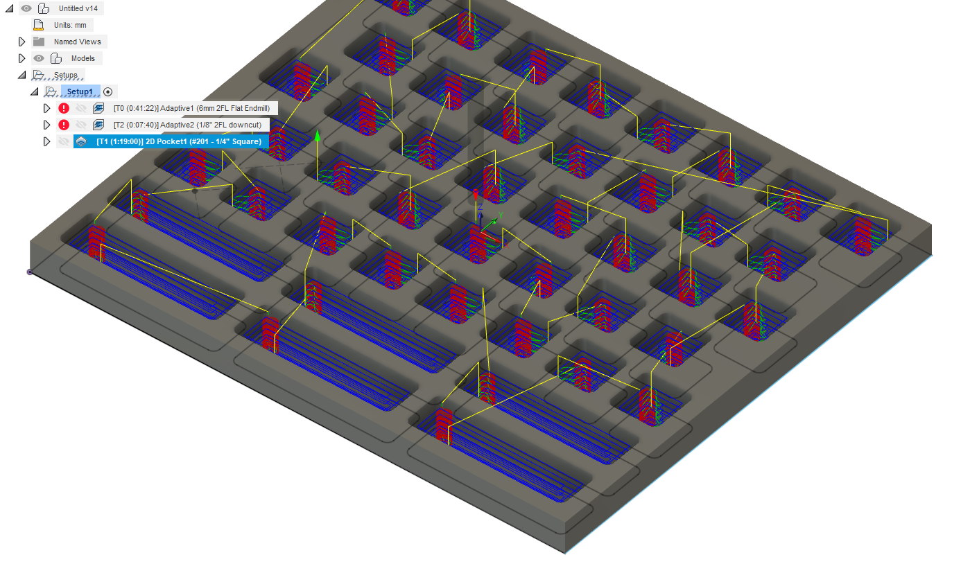
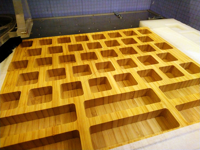
About the efficiency, it depends, in some cases it is does not make any sense indeed. The obvious case is slotting, where it will be always be faster to go in a straight line (even if going slower and shallower) than going round and round in small circles to carve that slot. But for deep square-ish pockets, it works wonders for me. One example I have is this bit holder I did a while ago:
The adaptive clearing toolpath to cut those 0.55" deep pockets took about 40 minutes to cut at 12000 RPM, 80ipm, 0.03"optimal load:
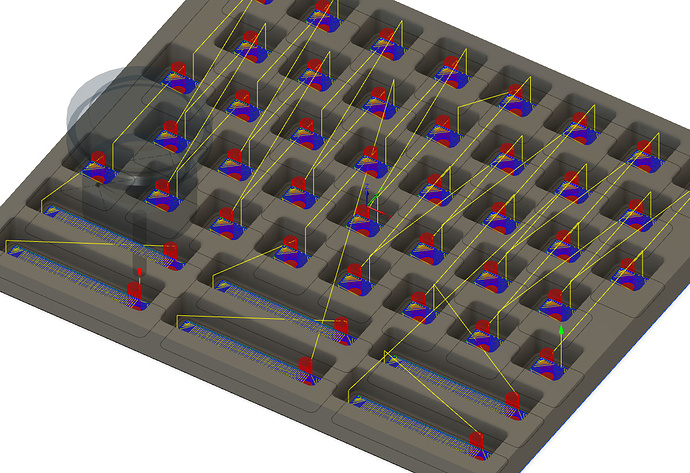
I tried generating a reasonable 2D pocketing toolpath with the same cutting parameters (same RPM, same FR, 100% stepover) but a 50%D depth of cut which is my goto rule when regular-pocketing, and it gave me this 1h19 minutes job:
also in the library/tool I’m building I should be able to calculate/estimate cutter engagement… sort of assuming there’s a linear relationship
so
speed = min_speed + (1 - engagement ratio of cutter) * (max_speed - min_speed)
Assuming that you’re talking about monitoring spindle power, both current and voltage need to be monitored at sufficient sample rates to enable the calculation of real power. Using an Arduino or other custom device to do all of that would be really nice since all of the COTS alternatives I’ve found don’t provide convenient digital outputs. Spindle RPM and bit diameter would then enable the calculation of approximate cutting forces. Do you know how to do that?