Theoretically the arduino uno, 16mHz clock speed, can sample at 9000 Hz, that would then be reduced by the complexity of the code around it. I think a sampling rate of 100 times/second would be achievable. The voltage could also be read easily and the power calculated. I don’t know what the current to the spindle looks like, is it a square wave with a variable amplitude or do they alter the frequency of a constant voltage? There are cheap oscilloscopes based on arduinos that could do the job. Here’s a project that uses the PC monitor to display the data https://www.instructables.com/id/Oscilloscope-Arduino-Processing/. The voltage would need to be reduced to the 0-5V range and I prefer to do the current sensing with a hall effect chip. All quite doable and probably cheaper than using 2 multimeters, 1 measuring voltage and the other current.
Cheers
Mike
ok that took longer than expected, but I have the “vcarve until the specified depth, and use a flat cutter to clear the inner bits” working.
One part of the delay was distraction (I’m building a enclosure for my shapeoko this vacation and well that needed time and attention during which my machine was out of commision)
But another part was a complete incorrect direction I went in.
I basically implemented what is described here (https://wiki.shapeoko.com/index.php/Carbide_Create_Basics#Clearing_area_around_drawing) and which @WillAdams recommends often…
…but after many hours debugging, it turns out that that technique is fundamentally not correct. It works great for large areas, but it falls apart if you have complex shapes (say text).
I had to throw that whole work away and implement a very different approach that so far works in all cases (in the easy cases it gives the same result, but in the more complicated cases it works correctly) which required me to brush up on trig math since I don’t normally use that…
(“given two circles, give me the two vectors that are tangent to both circles” kind of math)
to explain why the method is somewhat broken, I made some examples with Carbide create screenshots.
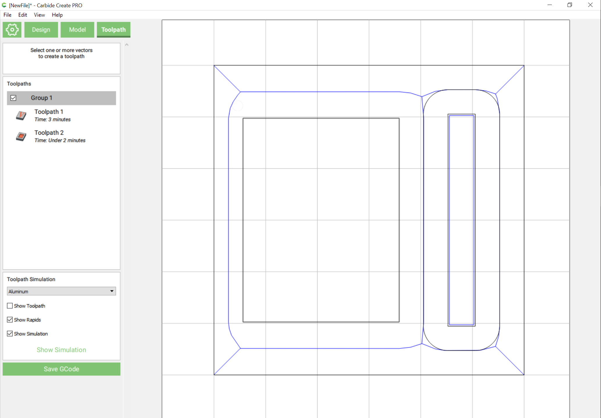
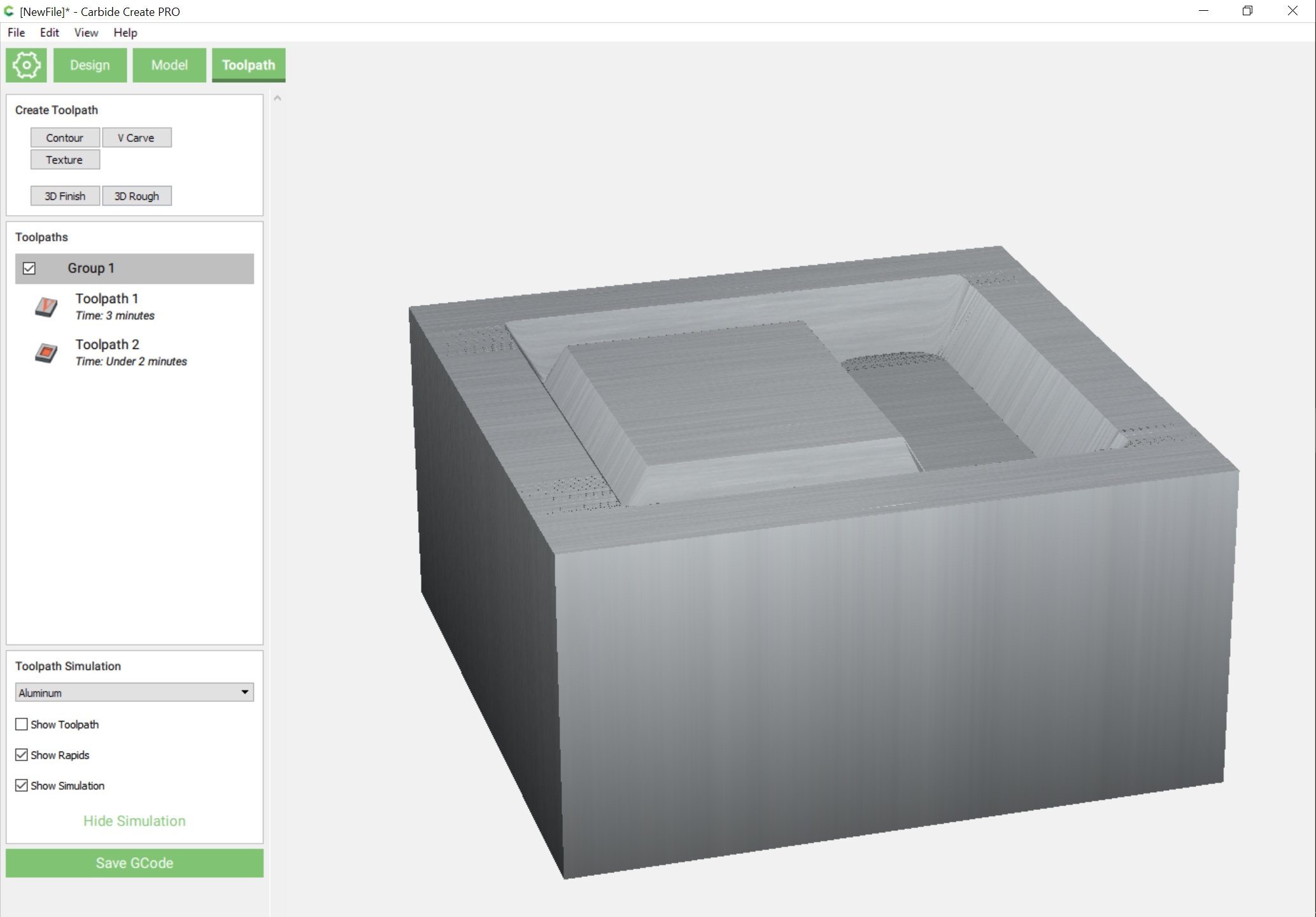
start situation is relatively simple:
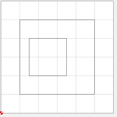
the area of interest is the narrow side of the inner cube where there is 0.5" of inner space
if you apply a small inset operation you get a great result:
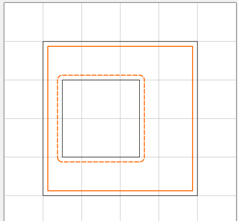
and the method works splendid in this case.
but as you make the inset larger you start to hit this corner case:
(0.25" inset)
this STILL will work ok…
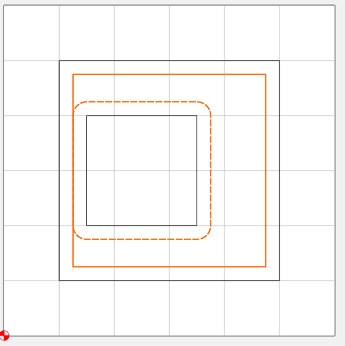
But when you go larger than 0.25" but smaller than 0.5" things go bad:
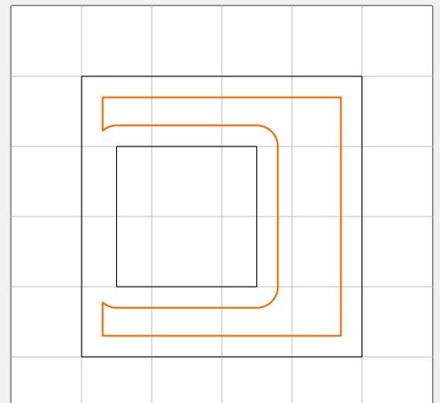
(this picture is with 0.3")
once this happens, the vcarve still works, but it will silently go DEEPER than you wanted to, upto 2x deeper depending on the exact dimensions of the shapes.
hmm that’s what I did (select both)
if in your diagram the grid is 1" (as I had it)… what happens if you inset a bit less?
there’s a zone with small insets that work fine, then there is a zone that does not, and then it works again.
the problems happen when the inset is a bit over half the distance between objects, but not bigger than the whole distance.
Post the file you’re having trouble with.
vcarveinsettest.c2d (6.2 KB)
if you inset both of these objects at < 0.25" it works great.
from 0.25" to 0.5" it does the merging thing
over 0.5" it’s fine again
(in natural, non-artificial cases this will be very rare, you need the “channel” to be in a narrow range AND long enough at this narrow as well…)
Correct, you have to set the dimensions so that you can leave a suitable strip.
now that my machine is mostly back together… tried cutting some wood with a toolpath created. The toolpath looked awesome in CAMotics… but in real wood it was absolutely terrible. Back to the drawing board, already saw many things to fix just by watching the terrible
I finally got something that came out not half bad:
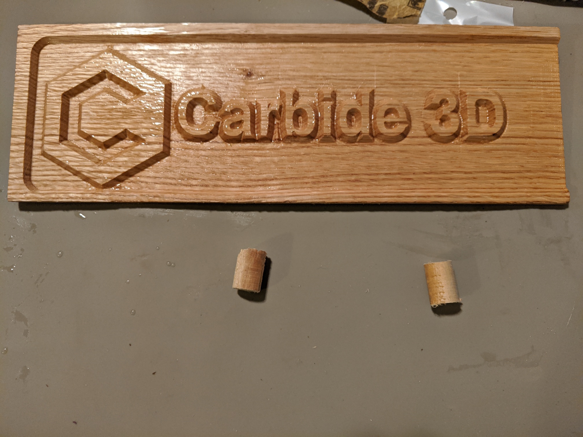
this was designed in Carbide Create ( libraryshowcase.c2d (210.6 KB) , exported as SVG (  ) and then processed as
./toolpath -d 0.125 -t 301 -t 102 -f -i showcase.svg
(sets the depth to 0.125", -f enables a finishing path… the command takes multiple tool options, so -t 301 -t 201 -t 102 would have first done a roughing pass with bit 201)
this gives the following gcode:showcase.nc (563.7 KB)
I made a recording of this in my new enclosure, so once I figure out the youtube side and edit it down for time a bit I’ll post a link here.
(I must say that I really like the finishing pass to make the flat area look nice and not full of tool marks and I wish carbide create would just implement that natively)
Can you please explain in laymen’s terms what you (your toolpaths) actually do and how they differ from the conventional? I’m totally clueless in that regard - so I’m sorry (and please ignore) if this is a stupid request!
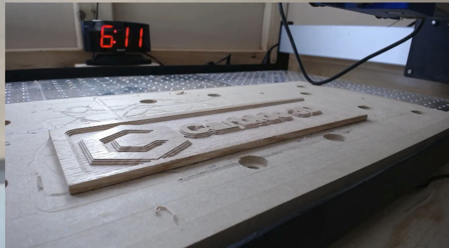
In some ways I;m building a library of building blocks with which I can do quick experiments. For example I implemented the “outside in” thing (not in the cut of this picture but I did one yesterday with it and I have a partial video of it).
Some of it was for me “how does this work” and figure out how these things are coded in software.
but what is different from, say, carbide create
-
Finishing pass - for pocketing operations, a stock-to-leave of (currently) 0.1mm is kept and that is cleared out in a final pass (that also has a bit less stepover so even less deflection/etc). My machine is pretty square but I’m surprised how much of a difference it makes in finish quality. (I suppose deflection kind of things)
-
Get rid of those ridges and “fuzz” for cases (as per earlier diagrams/pictures) where the current CC algorithm leaves “semi gaps” of more than the stepover
-
Vcarve with max depth/area clearing – you can mostly emulate this by hand in CC but only mostly. Hopefully the video will show what I mean; but the tool will not have “steep vertical” clearing but the flat bit follows the angle of the V bit in the area it clears, reducing the forces that happen when the V bit cuts
this picture was taken at the end of the pocketing phase before the V bit engages. Many of the parts the V bit will engage already have a cleared slope to them -
based on your suggestion, option for outside-in order for pocket toolpaths
-
multiple tools for one pocket operation, large tools for the bulk, small tools for the details
-
Run known evil paths (the “switch between the rings” little paths) at half speed to avoid big yanks that have costed me several pieces in the past that came loose from the workholding
that is what I’ve built so far over my Christmas holidays 
next steps of things I want to do
- make it generate two toolpaths so that you get automatic and accurate inlays
(this needed this V-carve-with-depth-limit-and-area-clearing to work) - a form of adaptive behavior, where the speed of the cutter is variable and depends on how much material it engages for each path where it moves…
and then allow this to maybe cut full depth (minus finishing stock-to-leave) and manage cutting forces via dynamically managing the speed
I still hope Carbide Create borrows as much as possible of these things… but so far I’m learning a lot and the building blocks/infrastructure allows for more experiments going forward
So you are applying for a job?
Heck no; I already have one of those
But I’m hoping that showing results is more effective than just asking for things with nothing behind it
So, given an svg, you generated the toolpaths for multiple tools through one command via command line? ![]()
You have my attention.
I’ll be honest, I was only half reading this thread because I mostly use Fusion 360. I’ve been doing some V-carve inlays with Fusion and your tapered pocket is one way I’ve done it.
How do you set feedrates, depth of cut, stepover, etc?
so on the F&S… I needed some file format to specify the tools so I just picked the CSV format that the beta carbide create uses since I already had all my normal bits defined with the F&S I like in there.
video of the cut (I reduced it to < 5 minutes from the hour+ cut, as to not watch paint dry): https://www.youtube.com/watch?v=CY7tznW-blw
unfortunately, as this is my first video, it seems my main camera had trouble focusing. I need to figure out how I get it to focus on the cutter and not something in the background
implemented the ability to do a “cutout” of a work piece from the same command line, which picks the outer polygon from the svg and turns that into a cutout toolpath.
A cutout toolpath has its own custom depth and will spiral from above the work piece all the way to this depth in one smooth path.
(this is different from carbide create that does a series of ‘rings’ at a constant depth, and it steps down in Z inbetween each ring)
More or less have “create inlay” working, but I think there’s a small bug in the math somewhere still; the glue is still drying so once it’s dry I’ll see how close it got
The process for doing an inlay is simple
Step 1:
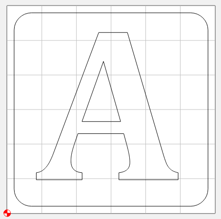
Create a design in Carbide Create:
A3x3.c2d (24.9 KB)
Step 2:
Export it as SVG in Carbide Create

Step 3:
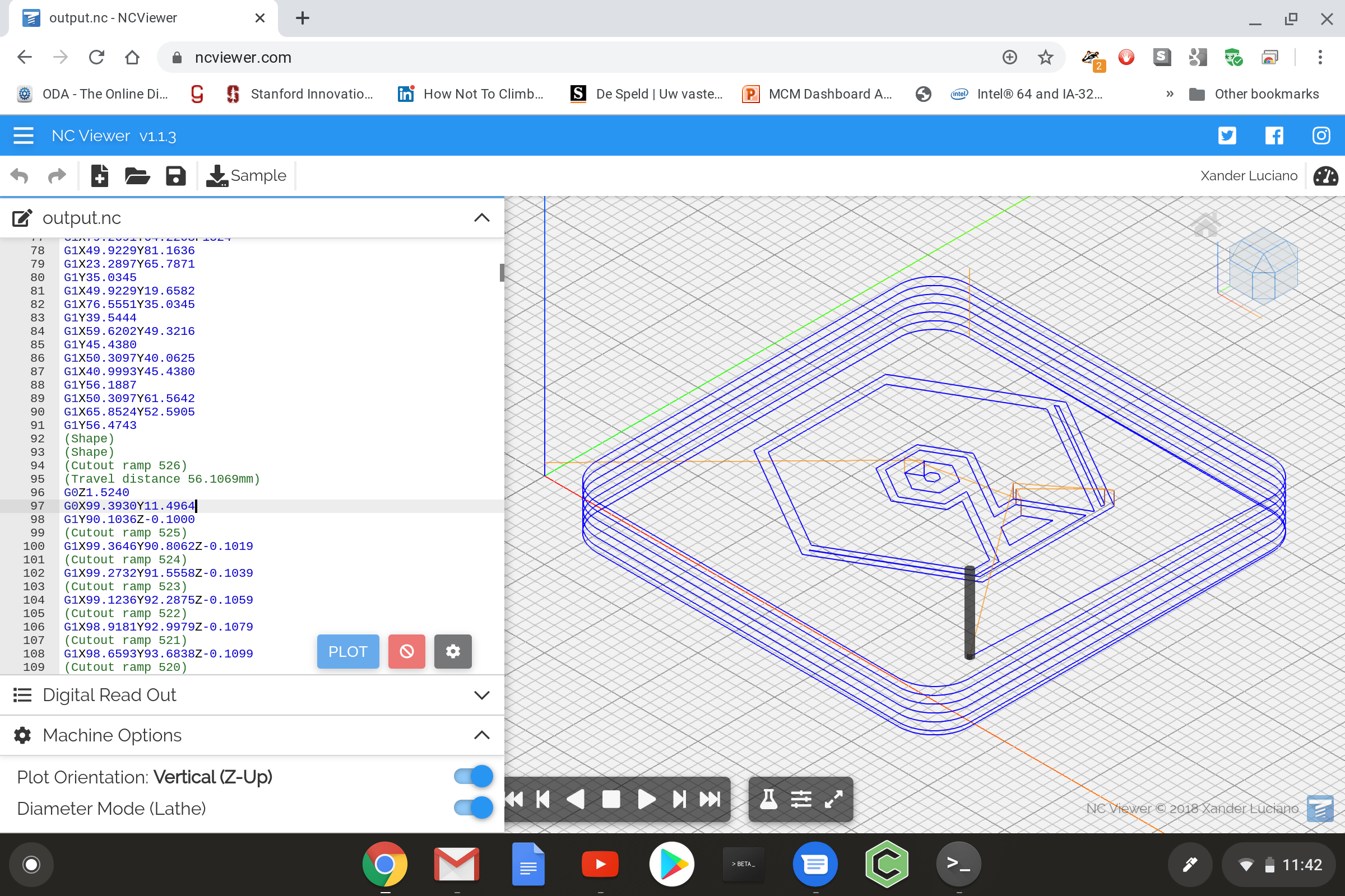
Run the tool:
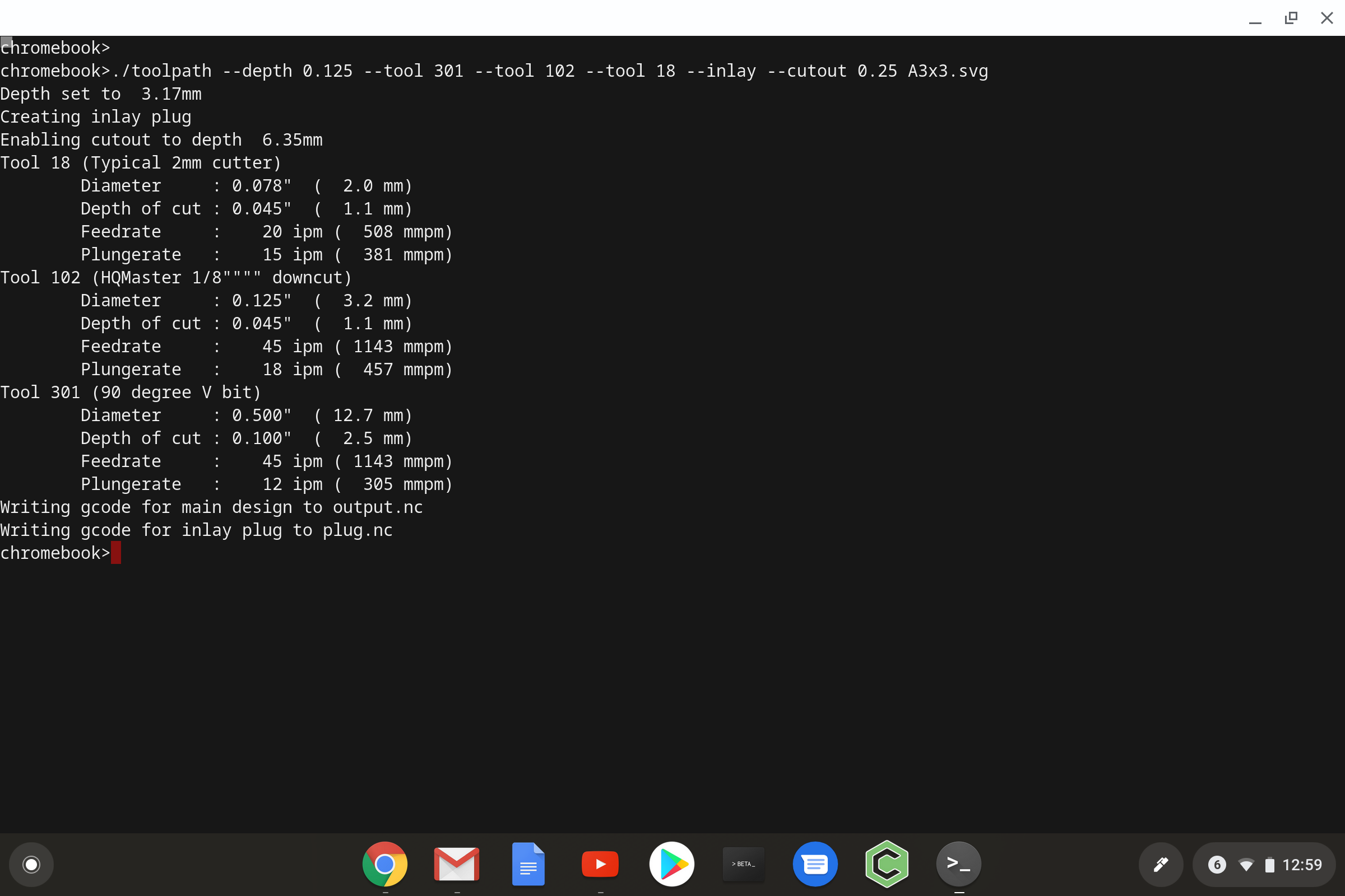
(here I’m using the new ‘cutout’ feature as well as showing semi-rest machining using both bit 102 and a 2mm smaller cutter (#18 in my Carbide Create library)
The tool will create 2 gcode files in inlay mode: One for the normal cut, and one for the “plug”
Step 4:
Load the normal cut gcode into carbide motion
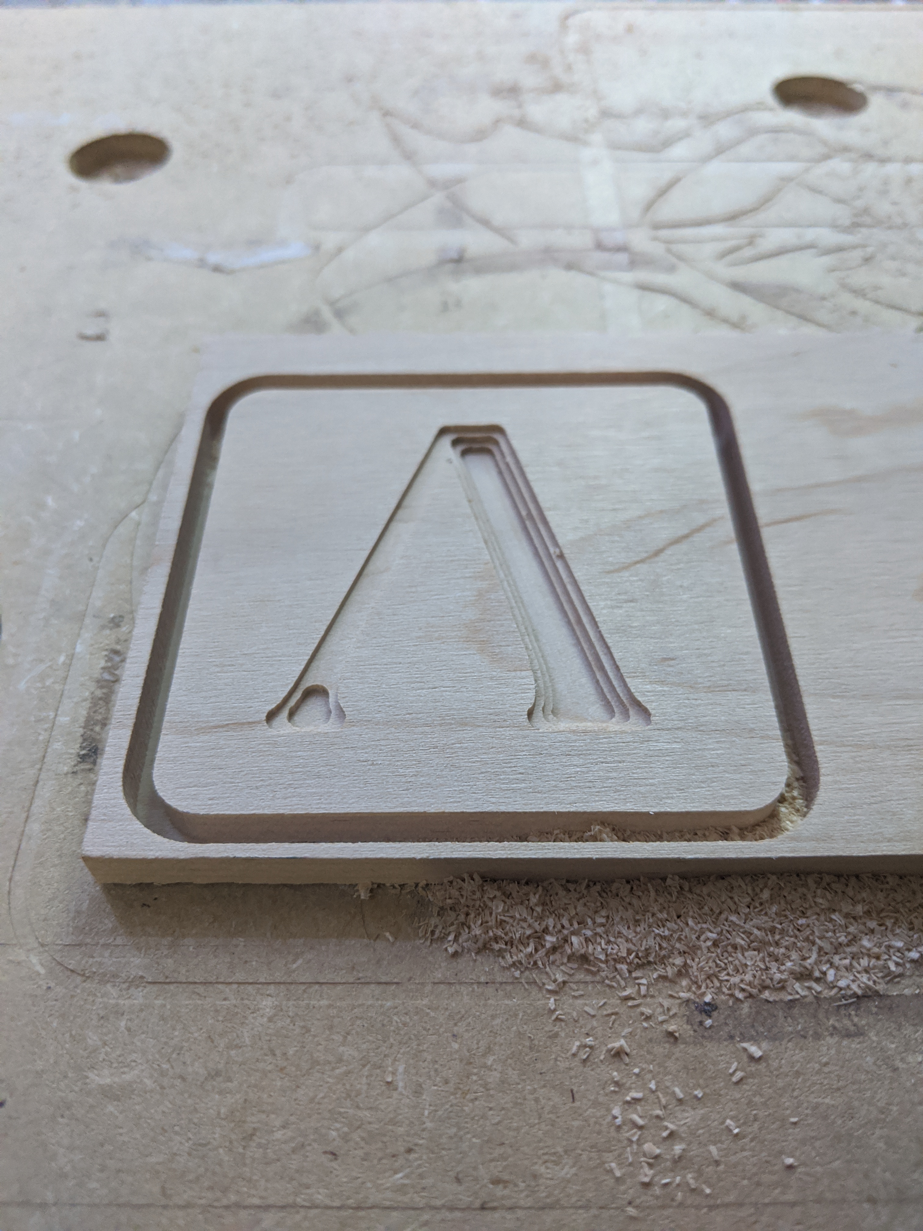
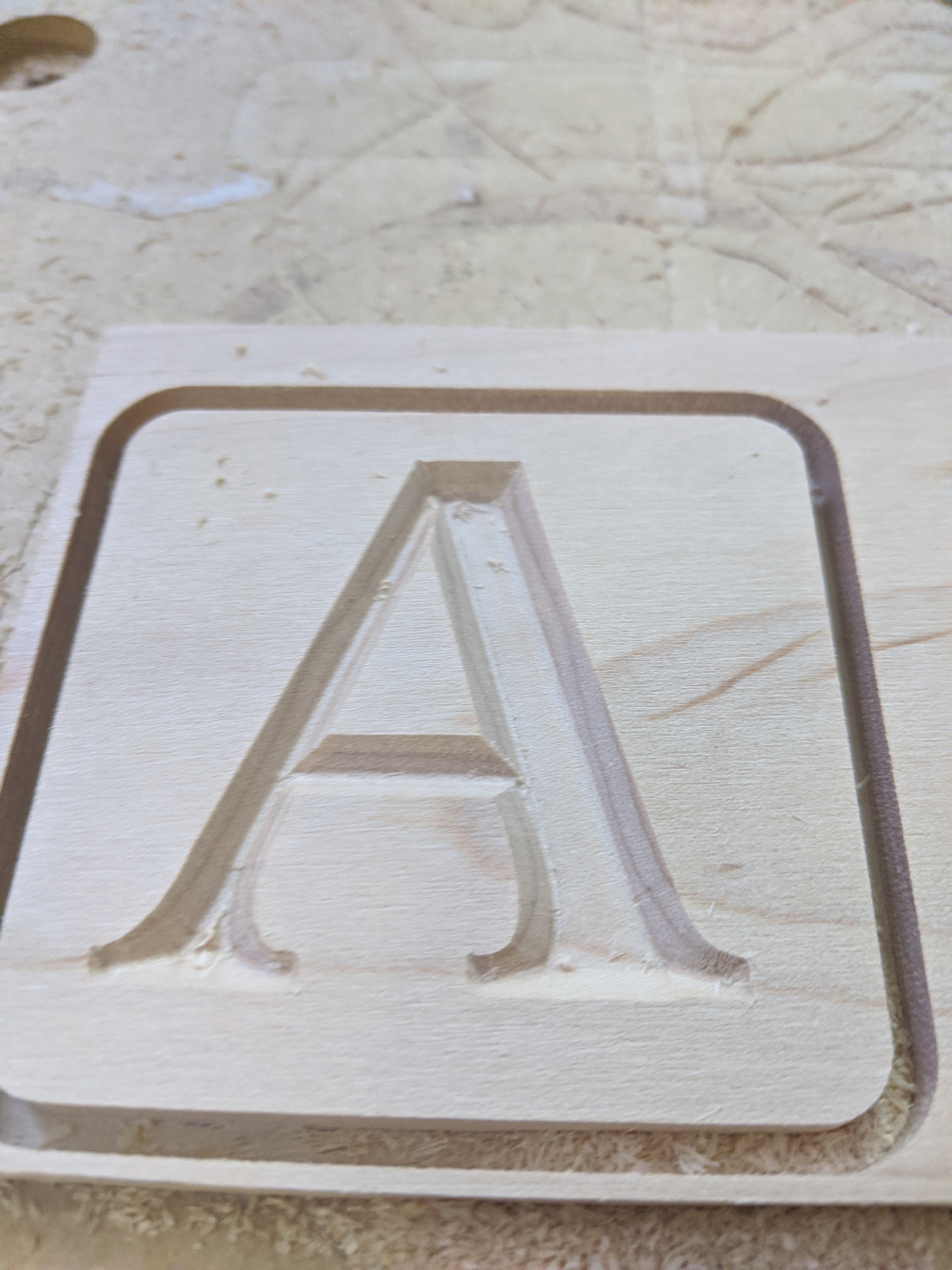
(after V bit carving)
Step 5:
Load the “plug cut” gcode into carbide motion
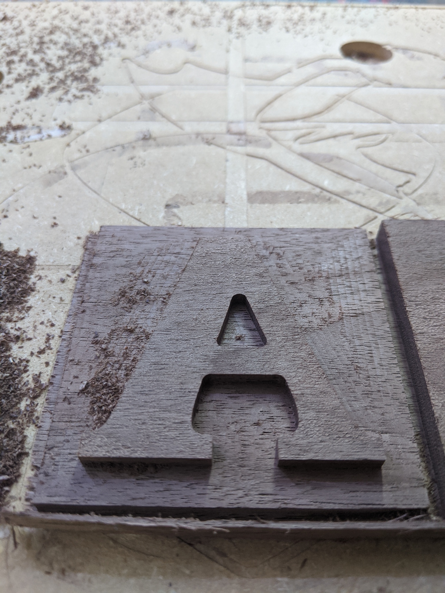
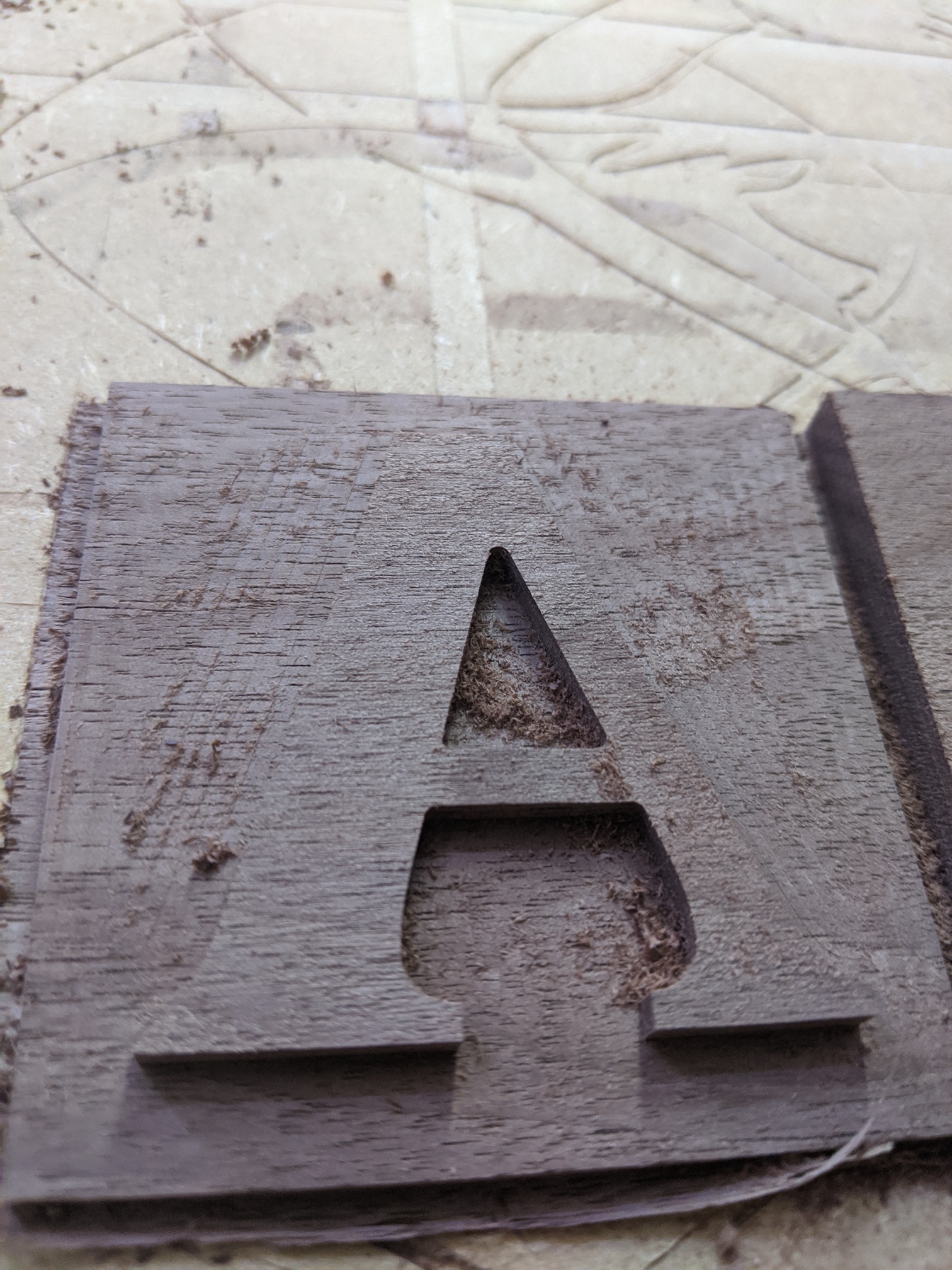
(after detailed cut with 2mm bit)
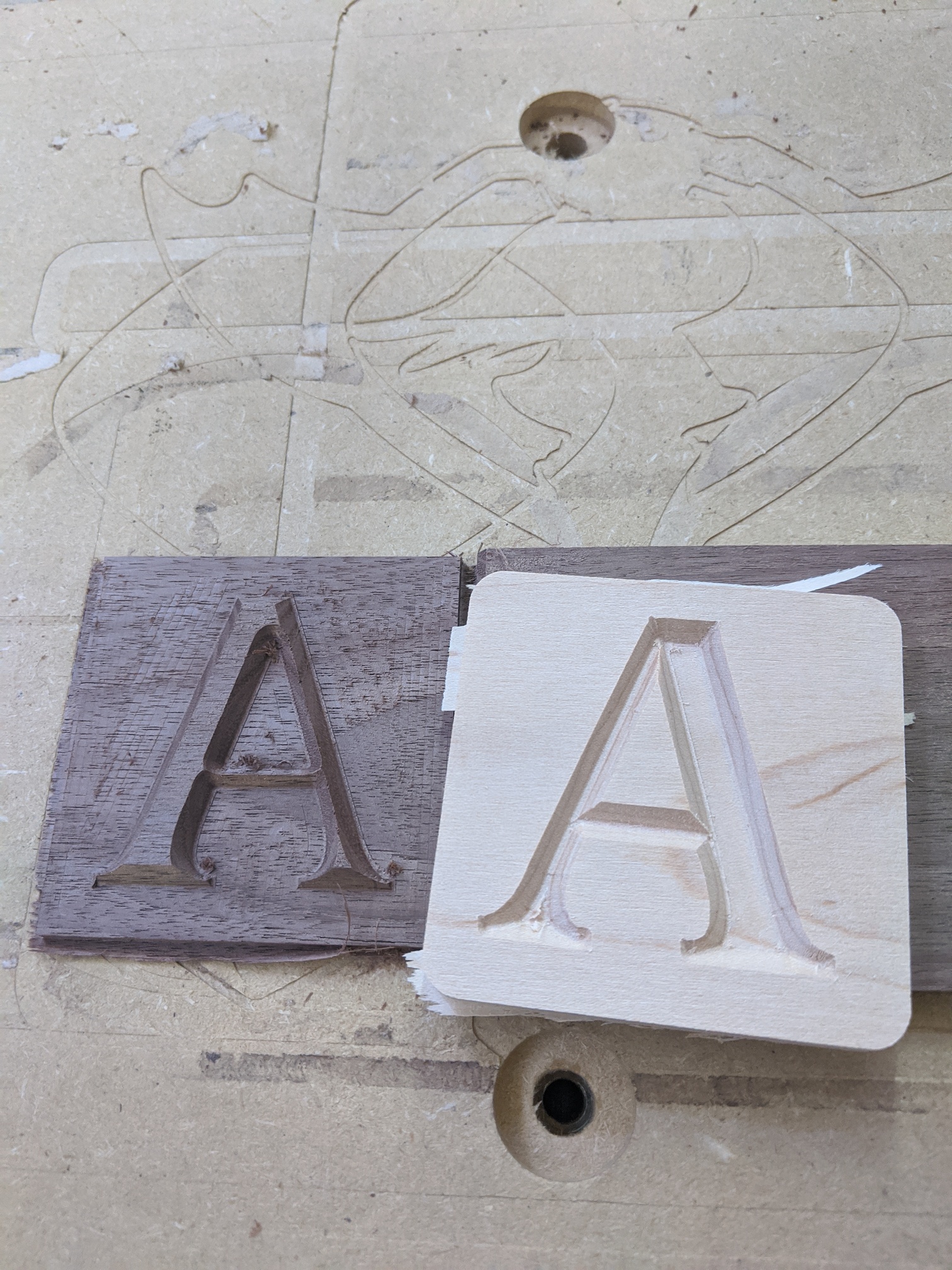
(final result)
I recorded the cuts on video and after minor editing (and setting most to 8x speed) the resulting video is approx 3 1/2 minutes… you can see the “no step” cutout process early on in the video: https://www.youtube.com/watch?v=yY7yvj_7mA4&feature=youtu.be