(fwiw I still am trying to get my head around how on earth I’m going to do that… but once I do I get rest machining for free as well)
What part is complicated?
So the idea I have is to keep track of what is cut already and what not, and then for a path, calculate the intersection to see what the cut mount/cutter engagement is.
The complicated part is the keeping track part and to do that in an efficient way. Option 1 is to do basically what camotics does, option 2 is to “subtract” all previous cut paths from the forward path. I haven’t figured out which one is going to work
(and first I want to wrap up the STL cut feature)
Sorry - I was asking what’s complicated about the dynamic feedback approach.
it means the gcode sender needs to get involved basically
also… any force measurement is backwards looking with, at best, a small delay… how much the past is a predictor for the future is a curious question and depends a lot on the geometry
That’s what control systems do.
1 Like
weekend update; decided to spend some time fixing bugs and add a CI capability.
So now I have a tool that takes a gcode file, and turns it into a “fingerprint” which has basic info (like dimensions) and samples the remaining material height at regular intervals (currently 1mm)… and can then later compare a new gcode file against the fingerprint to verify nothing really changed…
… and I added a set of test files in a 2nd github repo with makefiles setup so that I can quickly rerun these files, and then use the fingerprint tool to verify nothing bad happened in the code of the tool
4 Likes
Finally implemented adaptivedynamic F&S for pocketing toolpaths.
It’s not the Fusion style “do half arcs” but much simpler, calculate for the next bit of the toolpath what the actual engagement will be and scale the feedrate to the inverse of that (clipping to [0.5 , 1.2]) while assuming that the feedrate in the CSV from CC was set for a model of 50% engagement.
Engagement is a 3D property so “half of stepover” and “half of depth” are assumed equivalent.
For a “normal” inside out pocketing, when approaching a corner, the feed rate goes like this
100%
100%
83%
63%
52%
– corner
100%
while the “outside in” approach starts with a full perimeter pocketing at 50%, but then goes to a mode of either 100% or even 120% (for the corners)… assuming a nice square.
4 Likes
ok playing with various models from thingiverse… it seems that the limit for toolpath currently is roughly 3.2m vertices… (e.g. a 162Mb STL file)… does anyone know how that compares to other tools (fusion360/etc)… is this close enough or do I need to spend some time doing more performance optimizations
2 Likes
I think (and have experienced) that it takes much less than that to take Fusion360 to its knees, on my PC that is.
Spare yourself the trouble of further optimizations, that will give you more time to work on adaptive toolpaths 
2 Likes
ok so the adaptive feedrate works quite well… it does all the things I expected it to do. I’ll attach 2 gcode files for reference that have this enabled.
It also is actually a lot less code and complexity than I expected… it really operates at the layer where gcode is being written out… makes me wonder how the new Carbide Create post processors work, since I suspect if those are an API kind of sorts this could be implemented in maybe 200 to 300 lines of C++ code in the post processor…
Simple square pocketing: square.nc (48.7 KB)
Complicated test shape pocketing: testpattern.nc (506.7 KB)
this gcode was done in verbose mode where for each gcode segment, it contains a comment for the estimated cutter engagement for that segment as well as the speed selected because of that
2 Likes
something tells me that that isn;t quite in my price range
but cool
1 Like
I spent some time (as a way to learn javascript) to make a webtool that in your local browser (so no uploading/server side processing) can analyze gcode and display cutting forces
https://fenrus75.github.io/FenrusCNCtools/javascript/gcodeforce.html
The output for a square pocketing operation from CC looks like this:
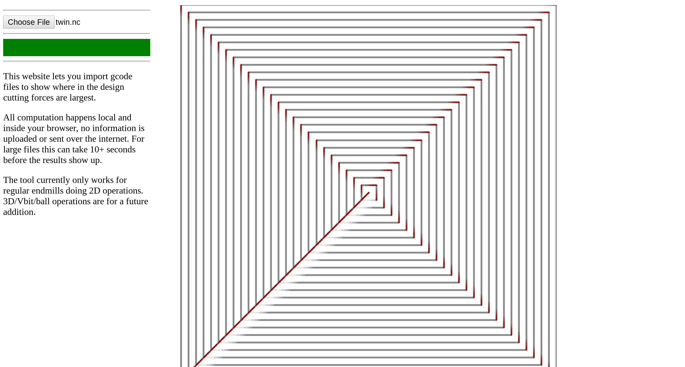
the lighter the color, the lower the cutting force, and once it hits a certain threshold the lines get a red-ish tint.
there’s various limits to this (2D only for now, flat endmills) and the color scale is rough (estimated based on the Carbide Create tool library for hardwood)…
but so far it’s been fun to see where forces are large
4 Likes
Very interesting! Well done!
Unfortunately I have tried a few gcode files - they seem to upload and the upload bar turns green - but nothing else happens. The gcode was generated by VCarve - is that the reason why?
could be I only tried so far CC created files. if you dont mind sharing a simple example from vcarve I’m sure I can make it work (I dont have vcarve myself)
sure - I will PM them
ok interesting the .nc file has NO information about the tool at all, just “T1”
wonder if we can convince the post processor to put a little bit more in
(even T201 would have told me quarter inch)
oh and arcs. will need to figure out how to add support for those
1 Like
added some early support for G2/G3 arcs as were in your file. urgh I hate arcs
also I faked tool 1 to be a 1/8th bit by default… but without any other info there’s not a lot else I can do in the simulation to make it more accurate than that
2 Likes