WillAdams
March 11, 2022, 1:20am
1
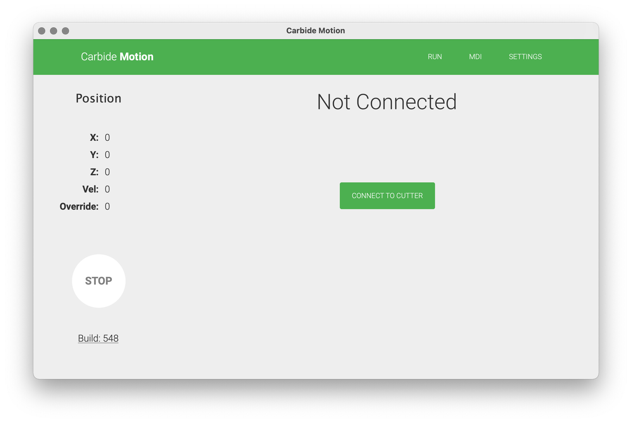
Power up the machine and launch Carbide Motion:
Connect to the machine:
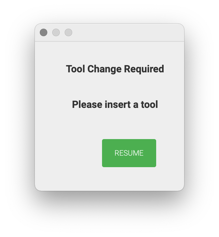
Initialize the machine — the screen will show as Busy — then prompt for a tool change:
Load a probing pin and Resume — the machine will measure the length of the probing pin.
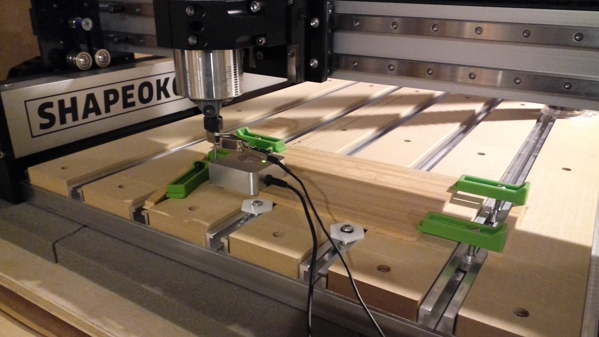
Secure the stock in place, position the BitZero and Jog the machine:
Since the probing pin was loaded before measuring and we intend to use it to probe the BitZero, click “No”.
At the Jog screen, use the interface to position the tip of the probing pin as appropriate relative to the BitZero.
WillAdams
March 11, 2022, 1:25am
2
and clip the ground lead in place:
For the specifics of using the BitZero see:
https://docs.carbide3d.com/assembly/bitzero/userguide
Here is how I check out the functionality of the machine/BitZero:
first check that you have sent the correct Z-axis configuration
This can be easily done by jogging down to the wasteboard surface, setting zero, then using the Rapid Position command to lift 6mm above the current zero — measure how much the machine moved — if it’s wrong:
go to the MDI and send $$ and check that the Z-axis steps/mm match your machine setup:
Belt-drive: 40
Z-Plus: 200
HDZ: 320
c.f.,
Then, clamp a sui…
WillAdams
March 11, 2022, 1:30am
3
Click on “Probe”
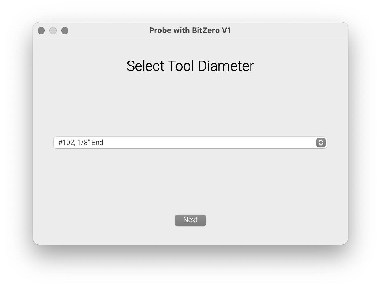
and click on the appropriate probing cycle — we will use Corner — if you have a v1 there will be a prompt for the size tool you are probing w/:
select the appropriate tool from the drop-down menu if that is the case.
The machine will prompt to test the BitZero:
Test that the BitZero will work by touching it to the tip of the endmill — it should turn red.
“Begin Probe”
The machine will probe the BitZero to determine the X, Y, and Z-axis position, after which X, Y, and Z are all set.
WillAdams
March 11, 2022, 1:51am
4
This of course assumes that we will be using a file which has the origin set at the surface of the stock and the lower left corner.
If need be, the unit may be repositioned and the Z-axis probed again.
Remove the BitZero unit and ground lead and store them so that they are not grounding out against each other.
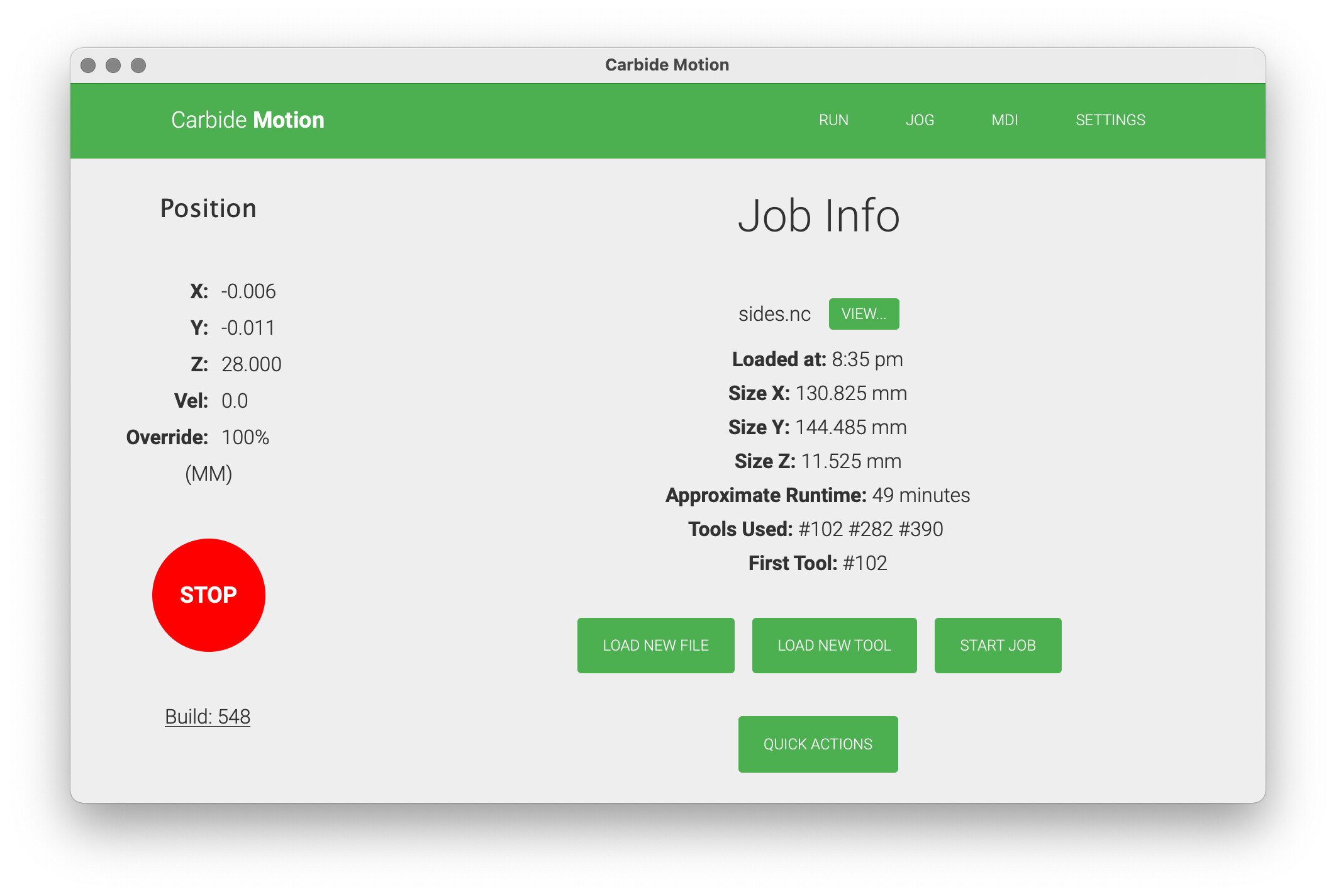
Click on “Run” to return to the main screen:
Load the file by choosing “Load New File” — navigate to where the file is and select it and allow it to be loaded:
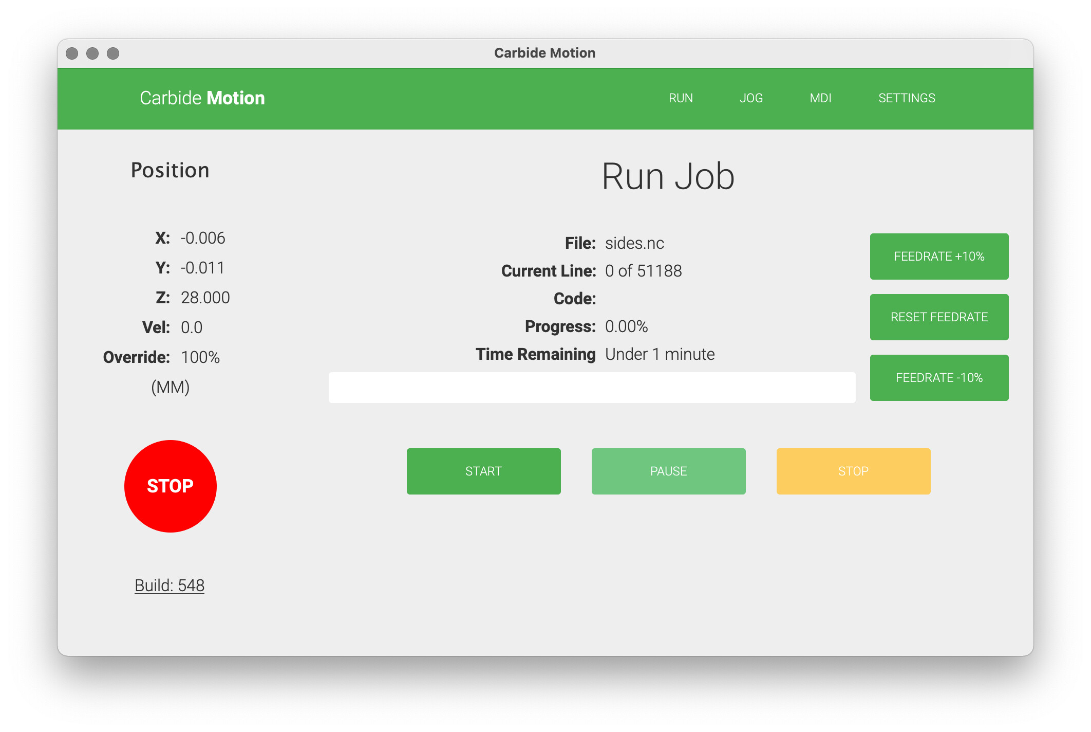
“Start Job”
“Start”
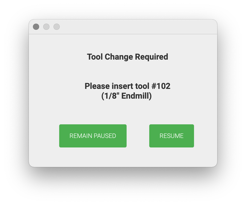
The machine will lift and move forward and prompt for a tool change — the Spindle Enable control should be off:
Load the requested tool and the machine will then measure the tool — after doing so, make any necessary adjustments such as installing the dust shoe, ensuring that the trim router power switch is on and has power and the “Spindle Enable” control is active after the tool is loaded. Check the Workholding. Put on appropriate protective gear.
“Resume”
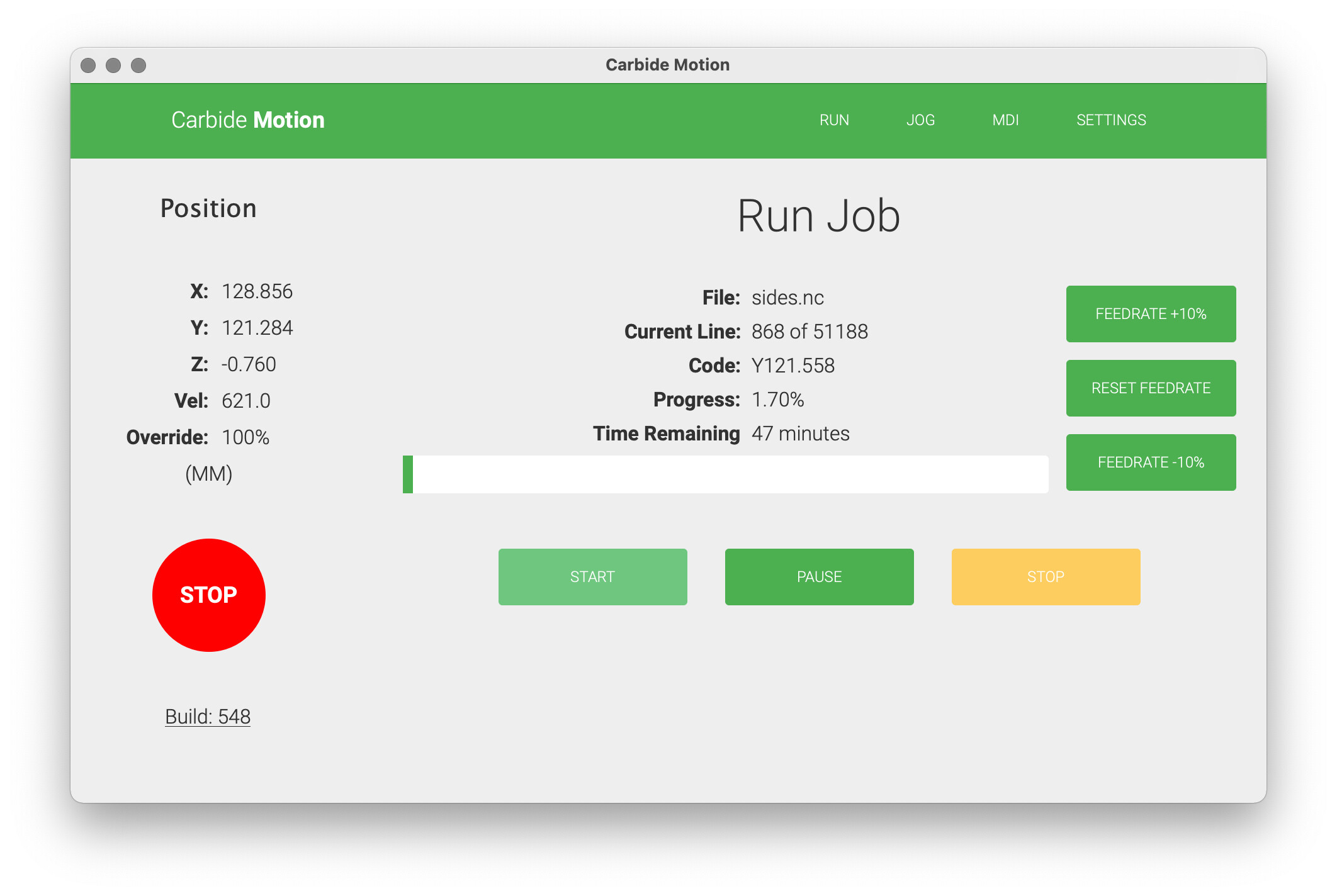
The machine will measure the tool, then lift, move to front center, power up the spindle and then begin cutting per the file.
WillAdams
March 11, 2022, 2:24am
5
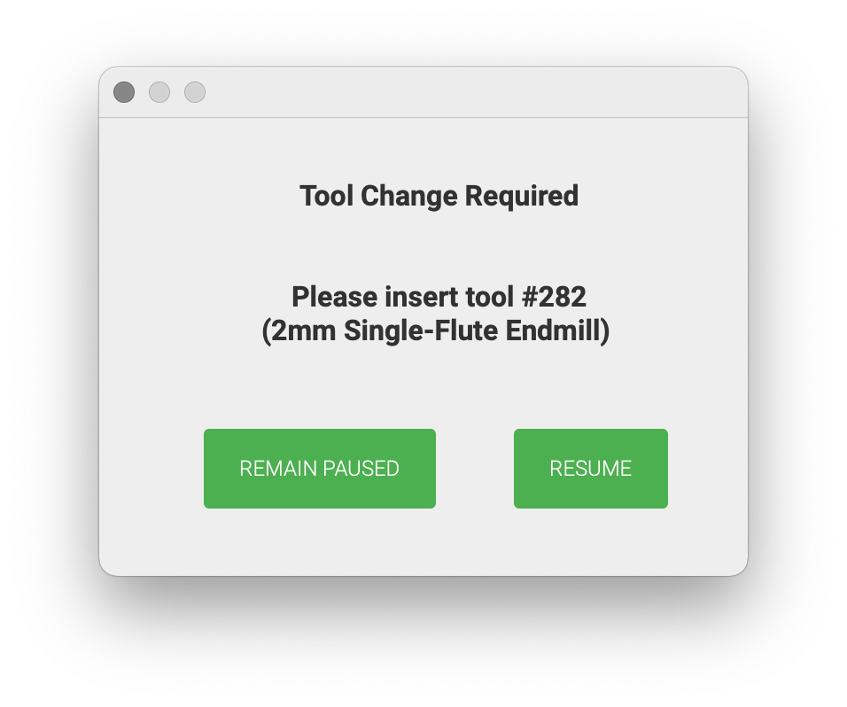
Once the first tool is done cutting, you will be prompted for the change to the next tool:
Turn off the Spindle Enable button, remove the first tool, clean the collet and nut and spindle shaft, insert the requested tool, and tighten the nut using a pair of good quality wrenches, then press “Spindle Enable” and click “Resume” once things are ready.
The machine will measure the second tool, move to the front, and turn on the router and begin cutting.
Repeat this process as necessary.
c.f.,
Be safe — wear appropriate safety equipment (esp. eyes (safety glasses/goggles), and ears (hearing protection — at least foam ear plugs)), ensure clothing, hair and jewelry cannot become caught up in the machine. If necessary, arrange for dust...