Daughter of Nomad (formerly "Full closed-loop vs. steppers. Worth it?")

Fair enough.

What I’d have liked to do is get accelerometer readings or plain audio recordings before and after and look at how the spectrum changed.

Also did the epoxy only act as a dampener or did it also reinforce the extrusion? If you push on the extrusion with your hand, does it bend more than it did before you filled it?

And more practically, I’d like to see whether you can push the spindle further without running into chatter, or whether you encounter chatter at different spindle speeds.

1 Like

I’ll pay attention next project and see if I can quantify anything.

The epoxy and sand has to have had some nominal effect on the beam stiffness as it added bending moment where there was none before, but most of the rigidity I would imagine comes from the aluminum shell based on the equations at play.

Maybe post-tensioning like they do with concrete structures could add stiffness? Boy what a rabbit hole.

This topic was automatically closed after 30 days. New replies are no longer allowed.

Finally, an update!

I’ve moved along relatively far since my last update. I’ve:

Here’s a picture of the servo assembly:

And the Y-axis from the top:

And from the back:

And a short video of the thing moving

I elaborated a bit on the process and reasoning over in the contest thread.

6 Likes

I really wanted to put a DTI on it and see if the servo can move the bed in tiny increments like I hoped. I don’t have a CNC controller for it yet so I used a Raspberry Pi:

for x in range(0, 10):
    pi.write(4,0)
    time.sleep(1/10000)
    pi.write(4,1)
    time.sleep(1/10000)

Side note: did you know the Raspberry Pi has a hardware clock that can be used to toggle the GPIOs? I can get up to the 4MHz maximum frequency of my servo driver easy.

Short test video.

At first I try to move it in 10µm increments, then towards the end, 1µm. The 10µm increments are mostly accurate but not perfect. When I change direction it looks like there’s ~5µm of backlash that shouldn’t be there. As for the 1µm movements, they’re so slow you can barely see them. It looks like the servo encoder does have the resolution though.

This is of course without any tuning whatsoever. I suspect this is going to improve once I’ve set that up.

2 Likes

I am really keen to see how you get on with the servo control system tuning. Specifically, how fast you can get the servos to approach target position and what sort of backlash compensation you can get without starting to produce nasty vibration or oscillation between the controls and the mechanical system, particularly as cutting loads start to drive the backlash.

Waiting eagerly to see your progress… :nerd_face:

1 Like

Minor update:

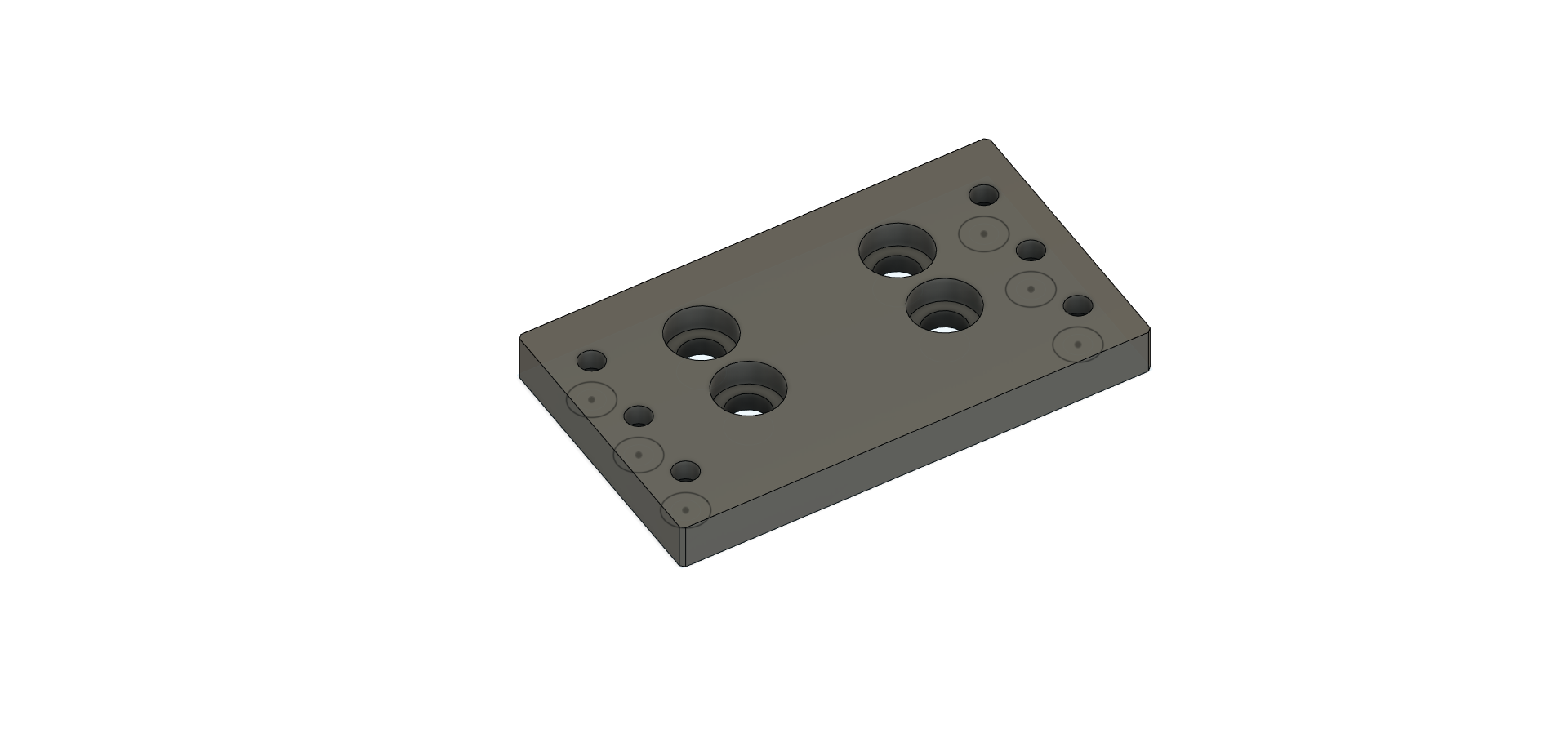
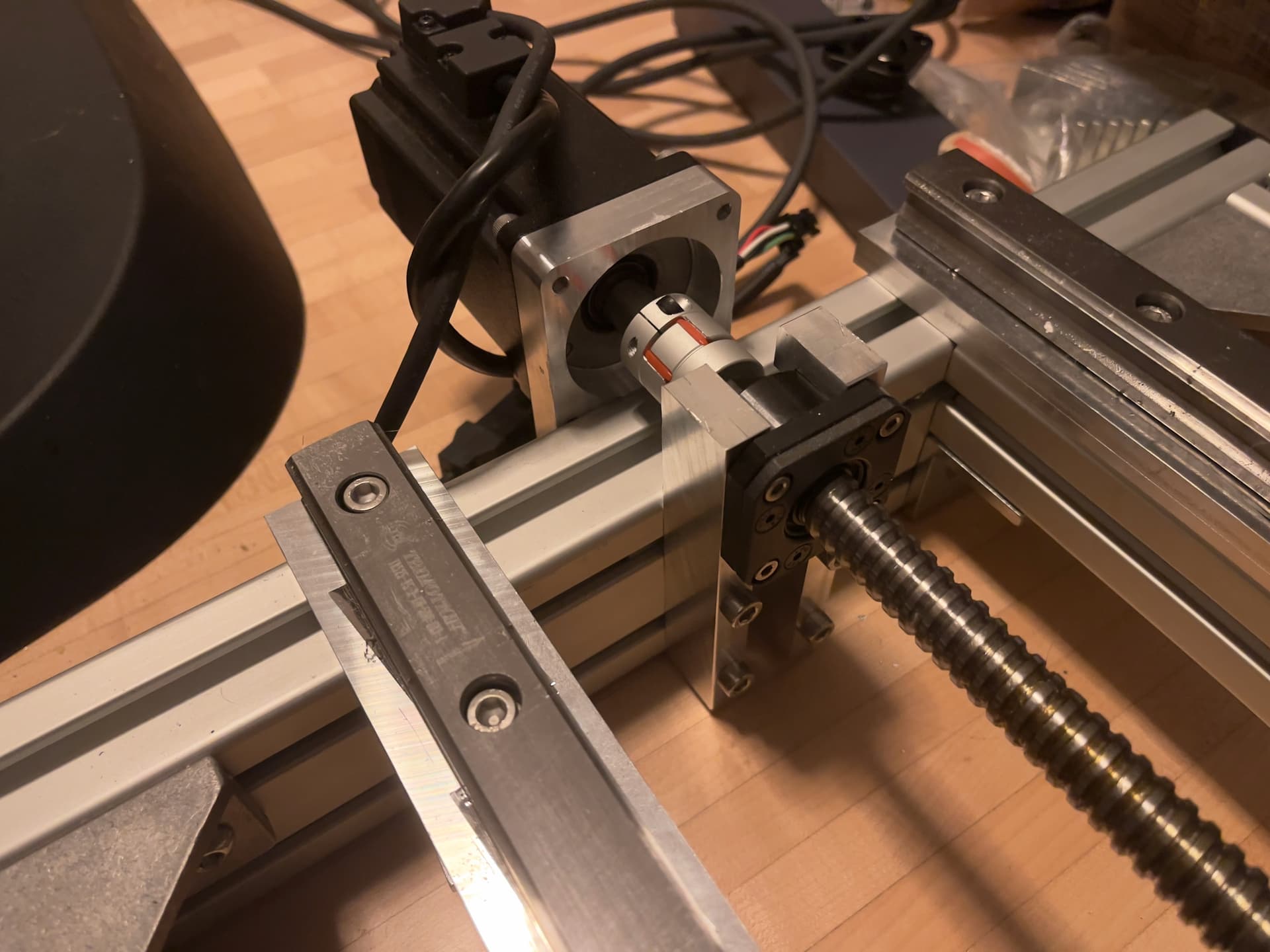
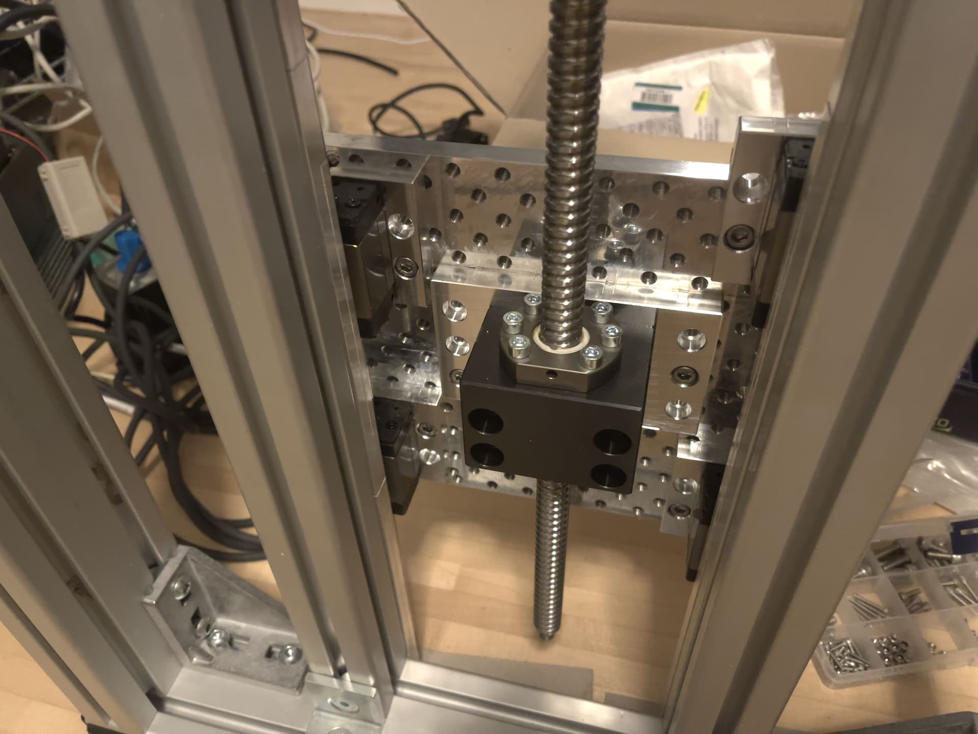
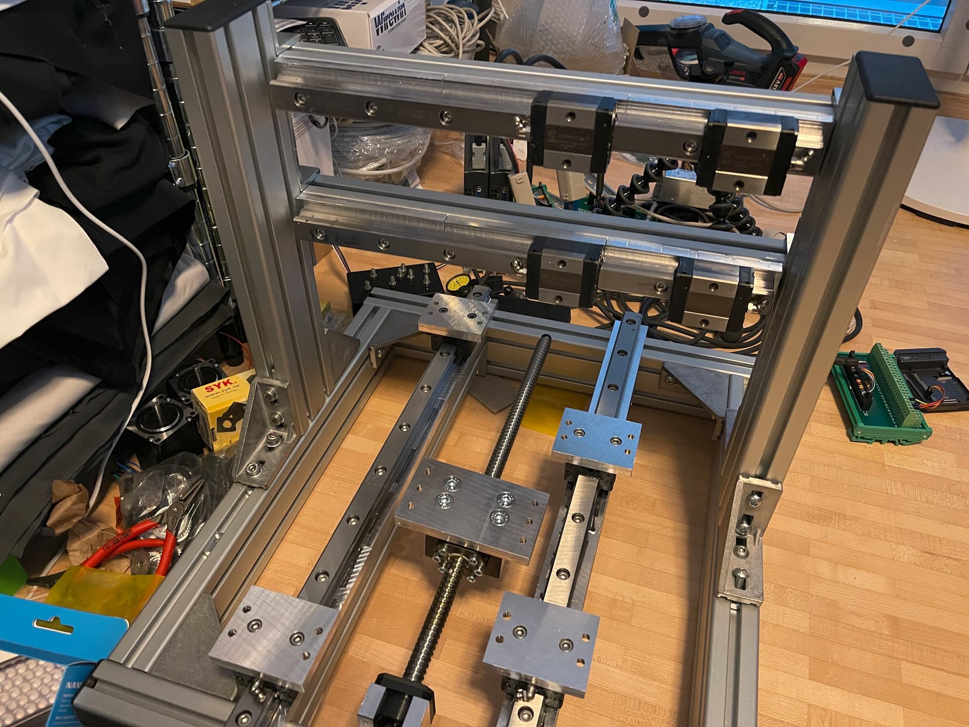
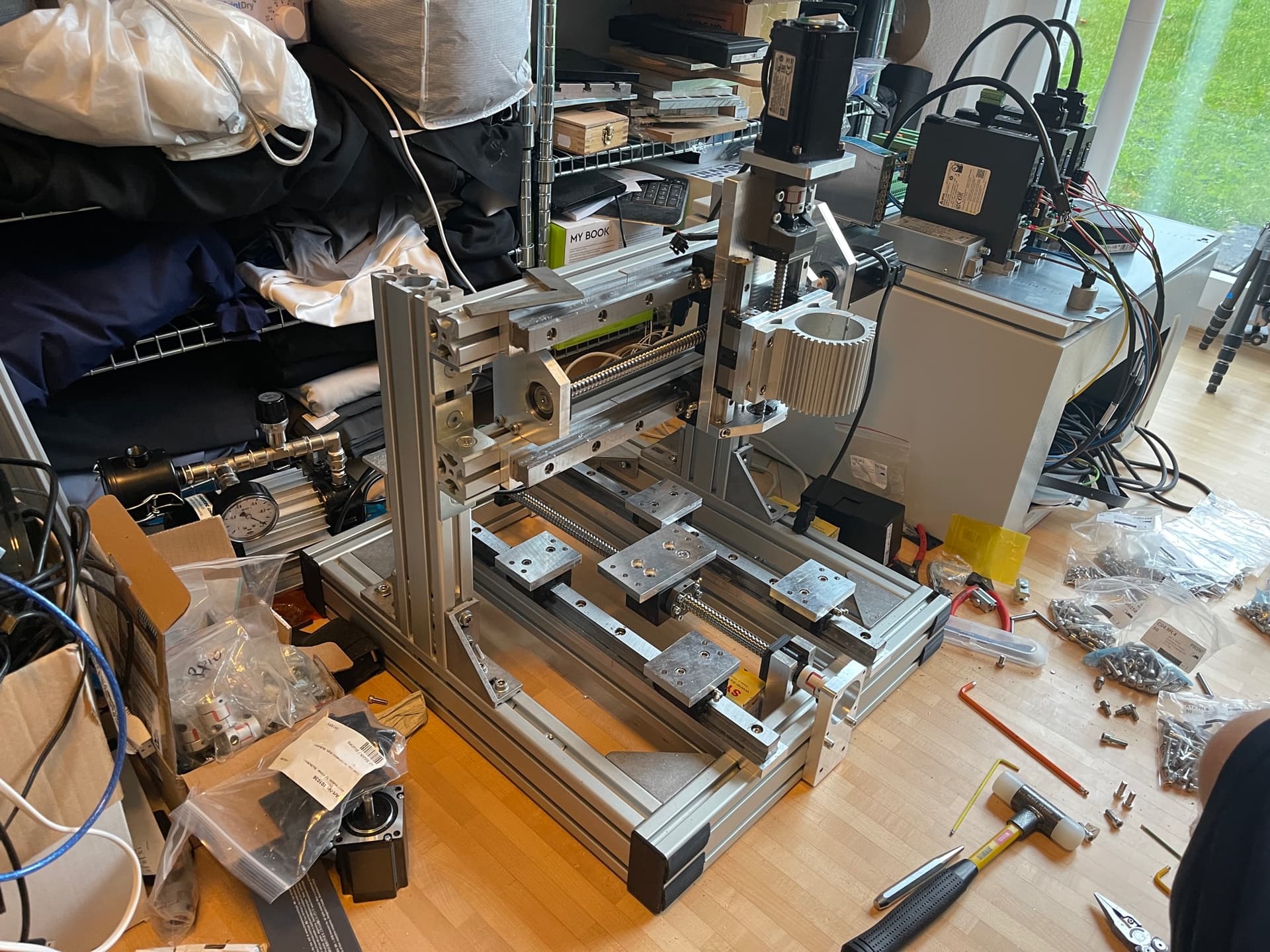
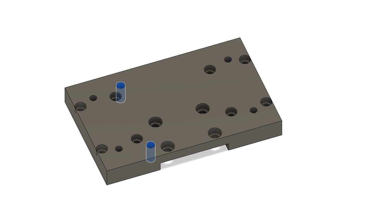
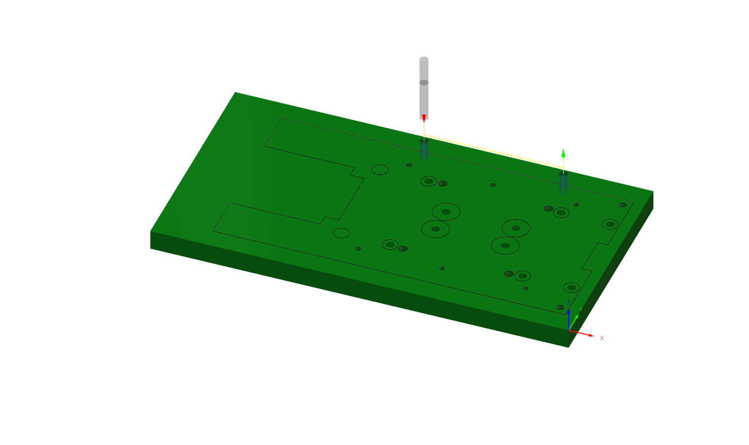
I milled the spacer plates for the X-axis:

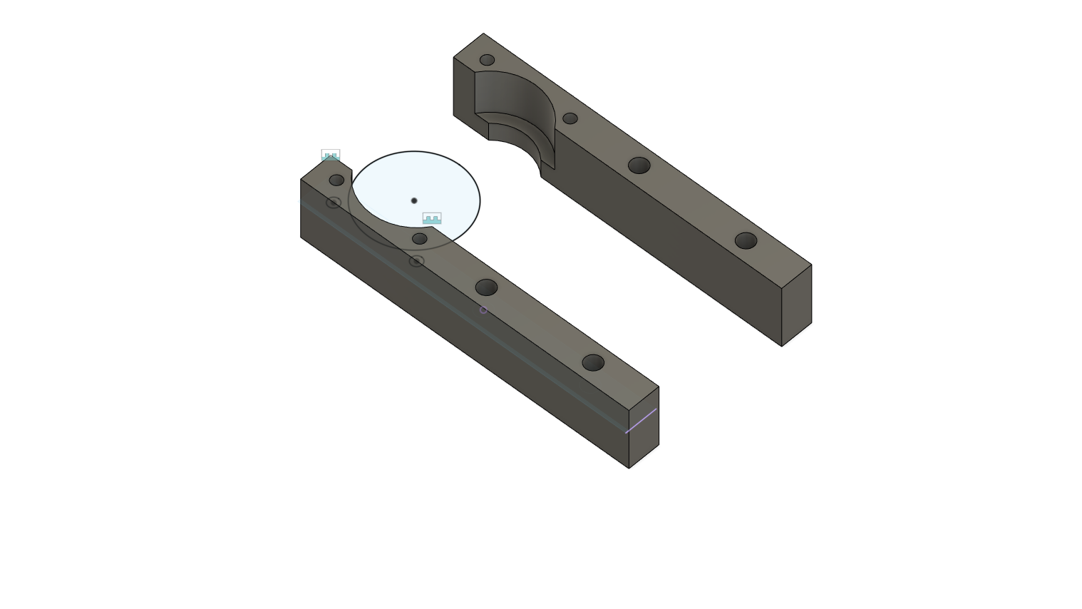
For the Y-axis, I milled them individually because that was really the only way to go about it. The Y-axis is 600mm long so the plates each need to be nearly 200mm.

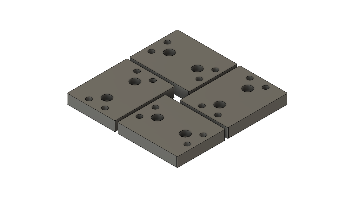
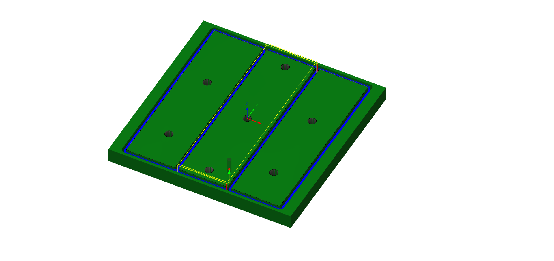
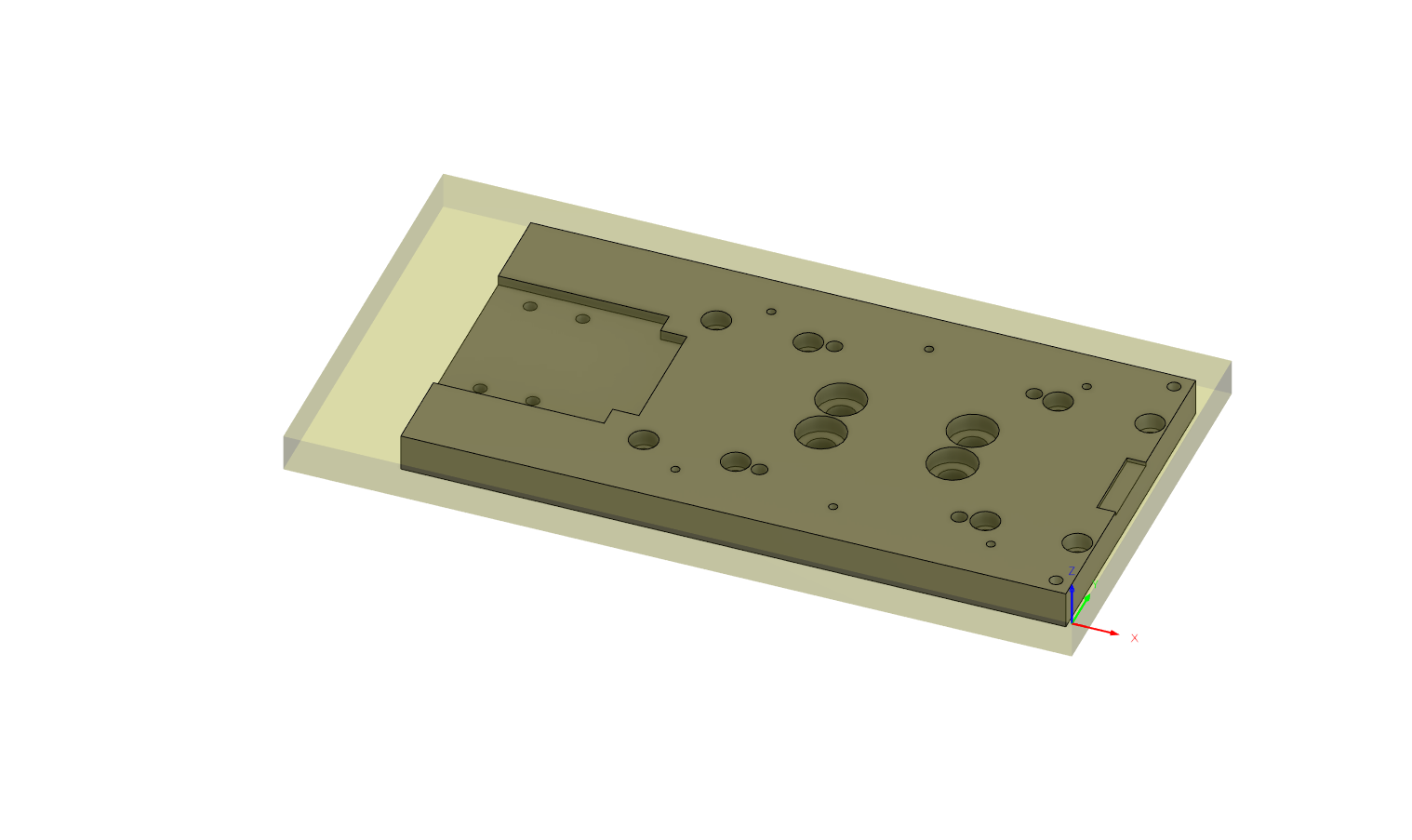
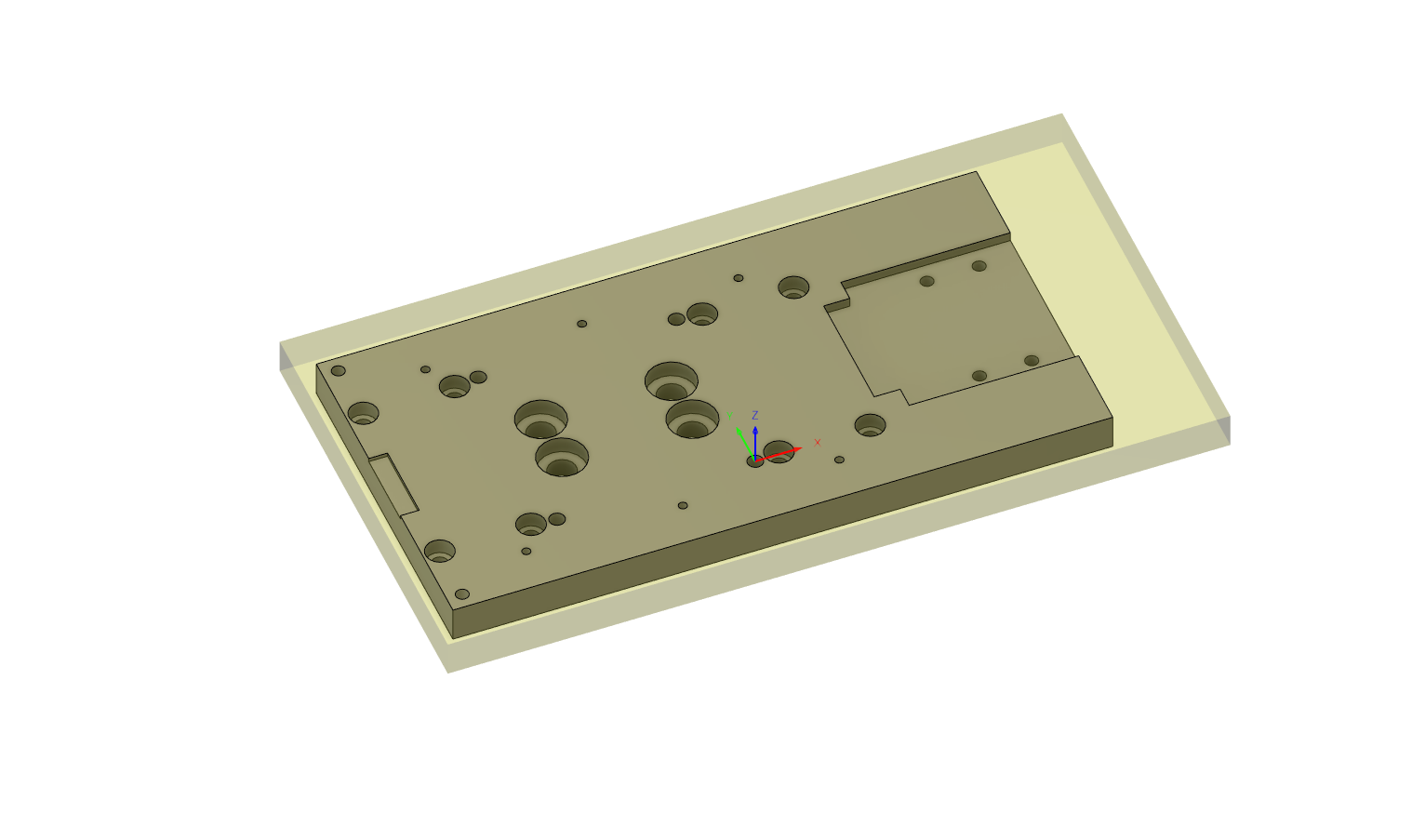
But the X-axis is only 420mm long, so each plate only needed to be ~140mm long and I could fit 3 of them in a standard (for me) 150mm plate:

That standard plate comes with a parallelism tolerance of 0.50 mm/m so for a 150mm plate, there’s a maximum of 0.075mm variation instead of the thickness tolerance of ±0.1mm. Half the shims!

I also “discovered” an easy way to zero against stock that hadn’t occurred to me before: when you can constrain two of your axes (e.g. a loose vise constrains X, gravity constrains Z but the workpiece is free to slide along Y), you can easily “zero” the mill by moving to a fixed position offset by the tool radius, then pushing the stock so that it touches the tool, then securing it.

That method is super handy if you need to mill a bunch of pieces of stock that are the same size.

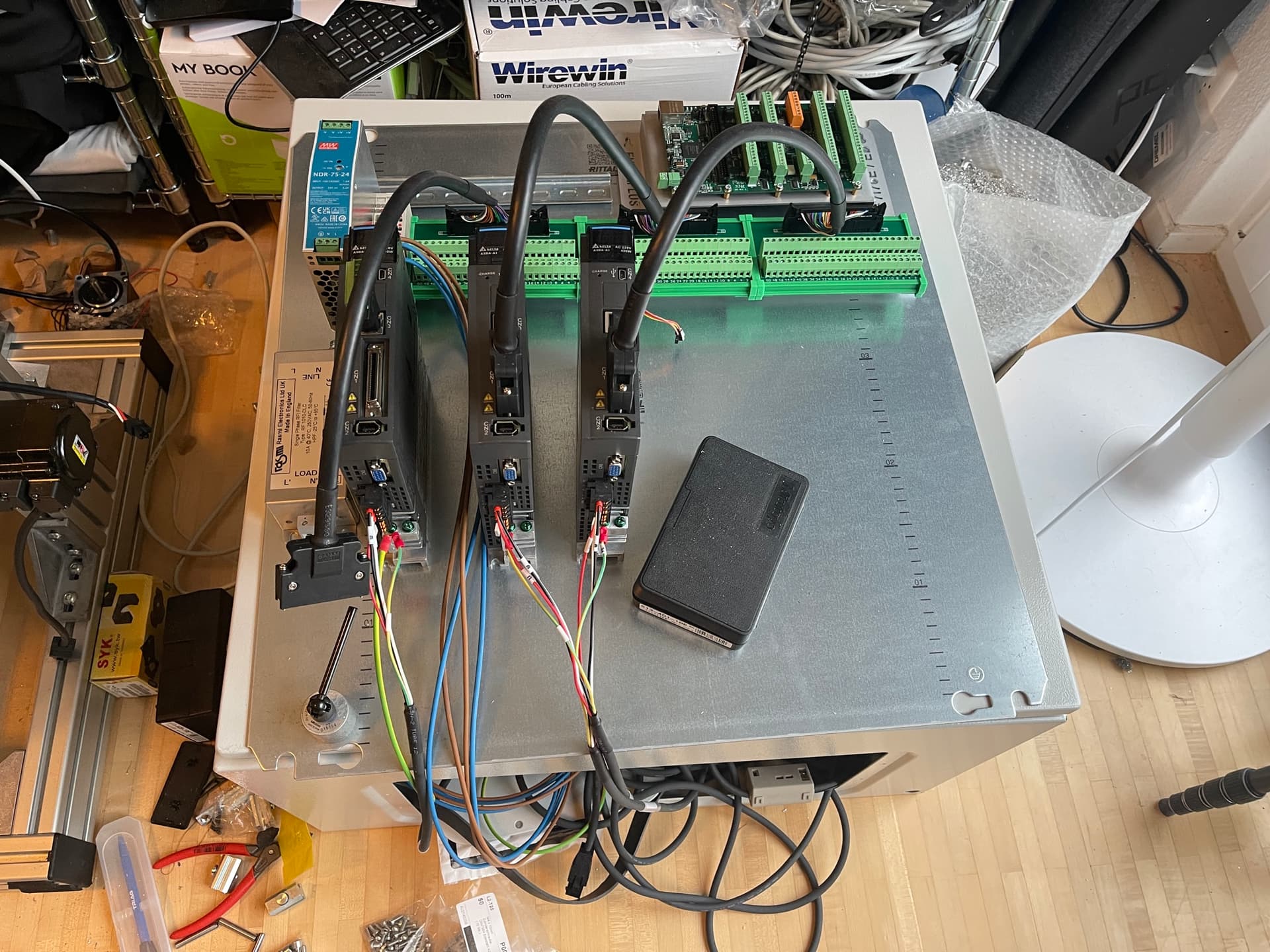
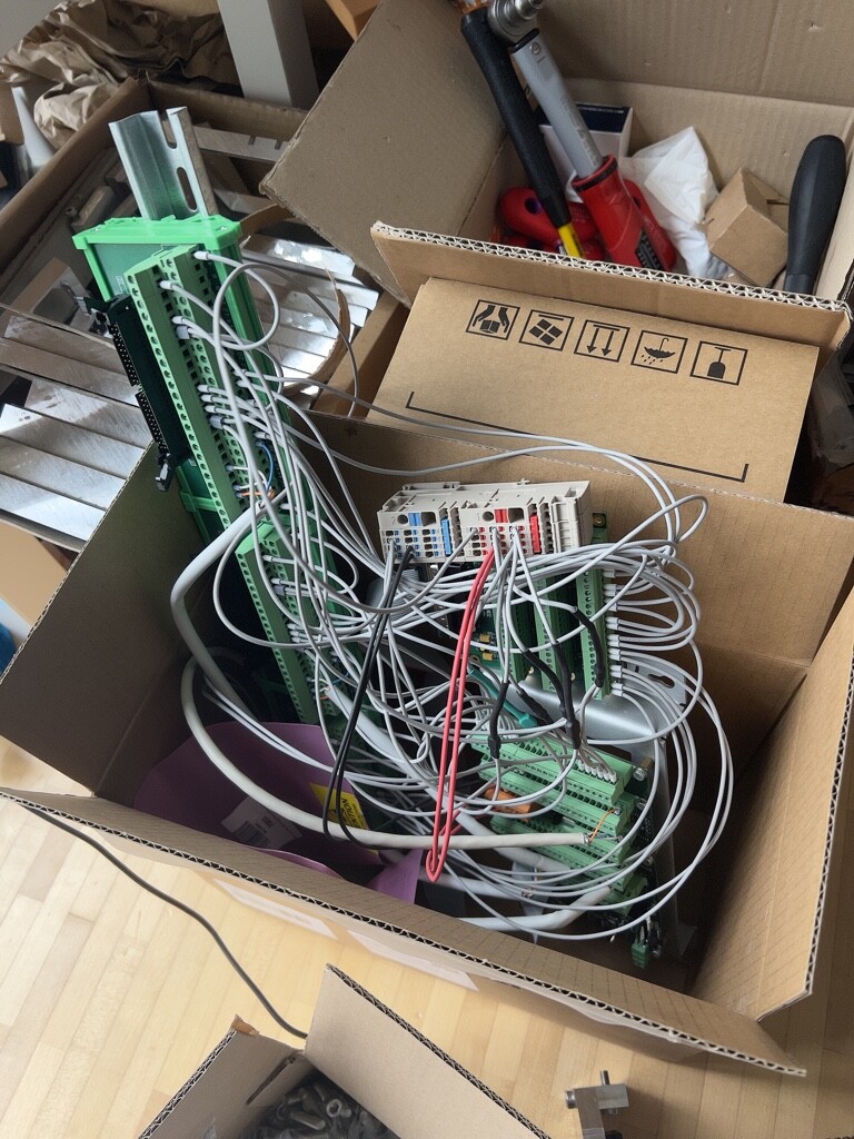
On controls, I prepared a PC with LinuxCNC and ordered a Mesa 7i76e.

On servos, I did try to play with the servo tuning a bit but the built-in USB interface kept crashing as soon as I switched the servo on. I think there’s a bunch of interference happening and getting in the way. I managed to get the RS-485 interface working but only at low baud rates. Turns out RS-485 is super picky and wants things like termination resistors that I’ve never had to bother with before. So I’ll add some resistors at some point.

I also have a Vers TSM toolsetter sitting around. Unfortunately I haven’t been able to play with it much because it requires that I turn the spindle on in reverse and I never wired it up. “Why would I want to put the spindle in reverse” were my thoughts when I was wiring up the controller.

I’m also contemplating ATC for this machine. There are two options I’m considering:

  • Spindtech ISO10, 800W: Funnily enough, this is actually the perfect size to swap out for my Mechatron spindle. I could make an ATC Nomad. It’s a bit pricy though.
  • Jianken JGL-80 ISO20, 1.5kW/2.2kW: Cheaper than the Spindtech, more powerful and with a somewhat normal toolholder (try to find ISO10 toolholders, basically only Schaublin makes them). Not sure yet whether my mill will be able to throw an 8kg spindle around though.

I’ve been looking at vacuum pumps too. Turns out I can probably buy a decent rotary vane vacuum pump for ~200EUR.

I also need to figure out what to do about the bed. The SMW bed I’m using from my Nomad is too small. I’m wondering about repurposing a Shapeoko bed. It’ll “only” be 300x300mm but I’m not sure what alternatives I have.

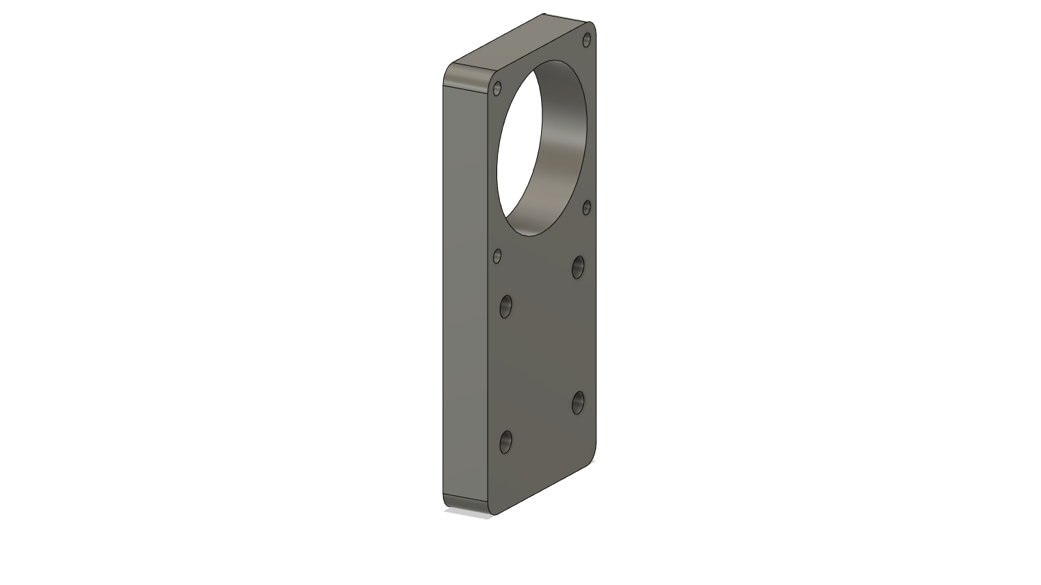
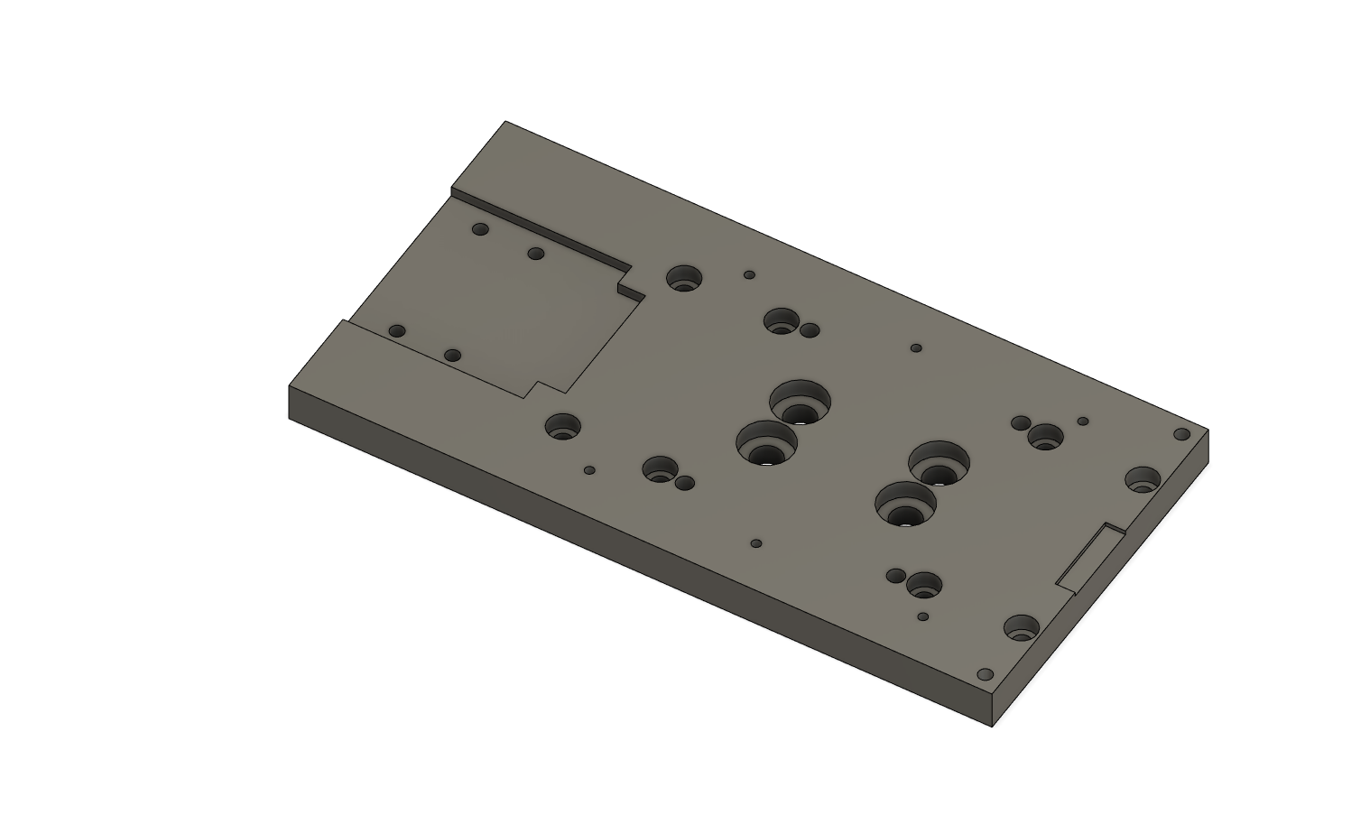
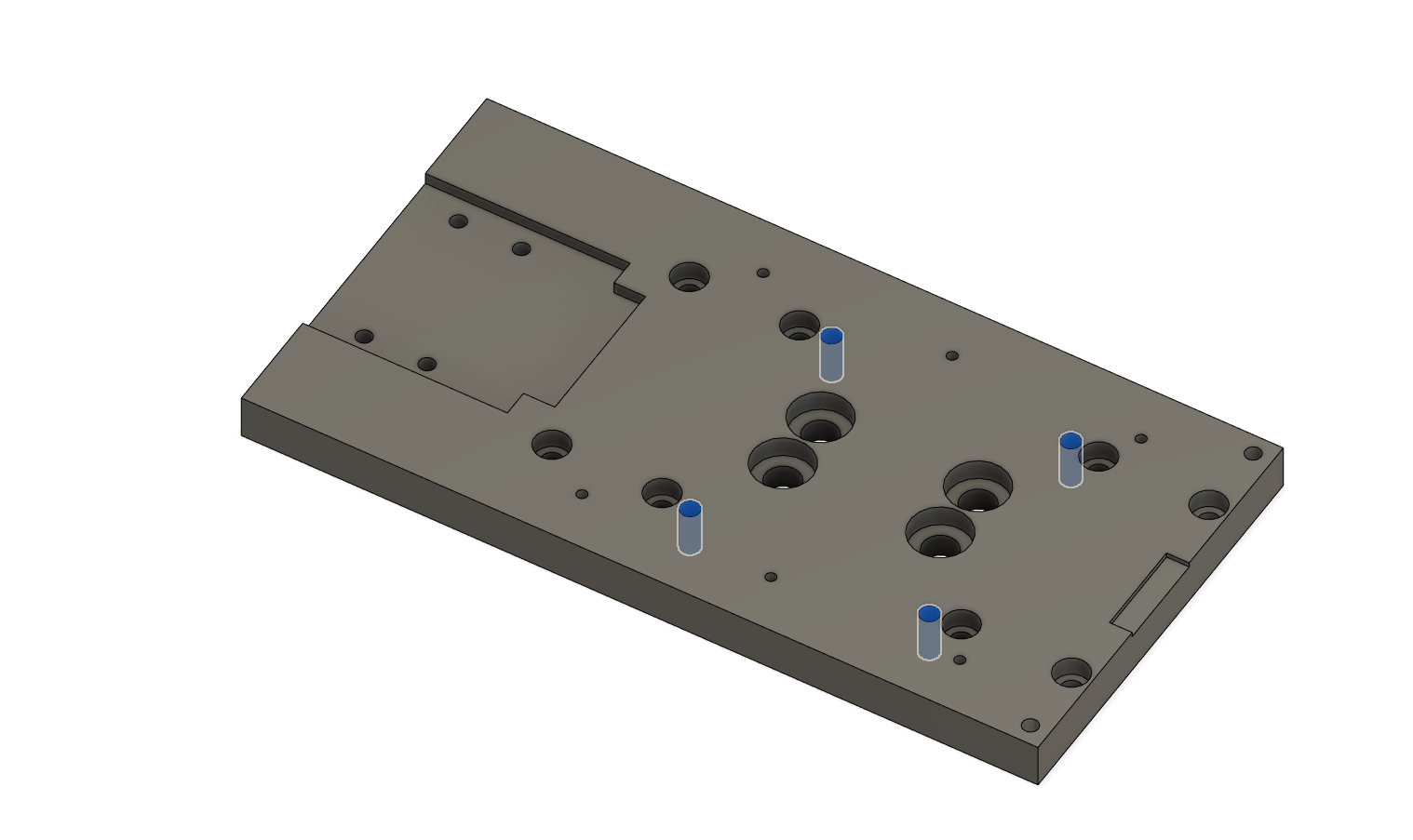
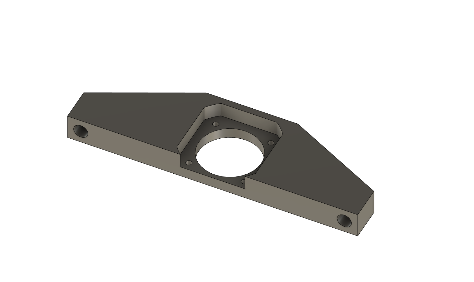
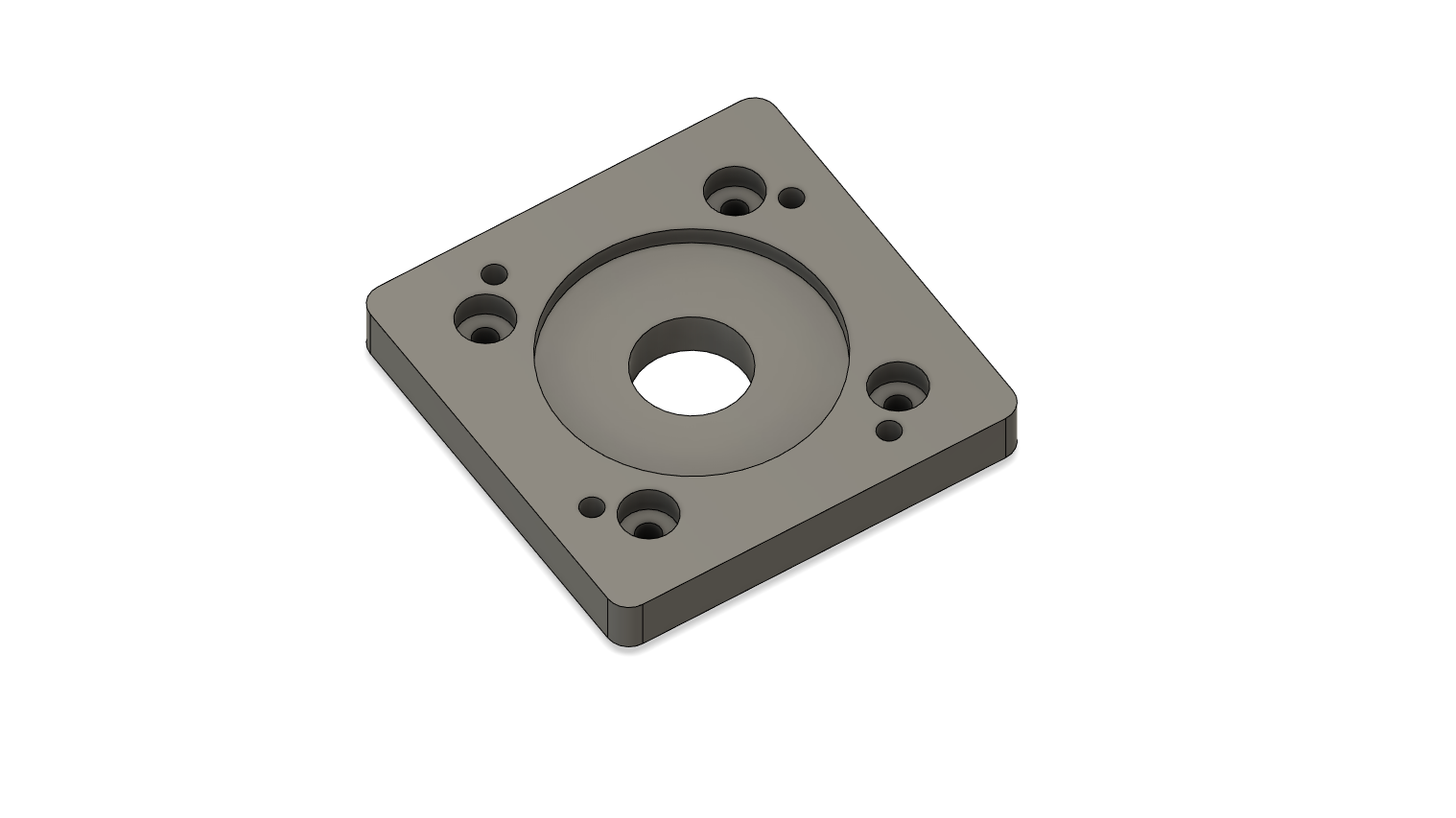
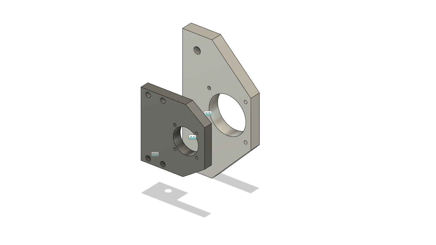
And finally, I need to figure out what to do about the Z-axis. Ideally, I’d modify the existing Z-axis plate. There’s a problem though: that plate is mounted to the machine I need to use to mill it. I’ll probably need to mill a new plate and buy a new motor bracket. While I’m at it I’m wondering if I should add a little more Z-axis travel and beef up the linear rails and ballscrew.

That’s enough ranting for now though…

4 Likes

All of the mechanical components are complete!

Here’s what the machine looks like now, for a test fit:

One thing I did for the test fit that I was really happy with was put alignment features throughout the assembly. It made it dead simple to mount the Z-axis so that it’s perpendicular to the X-axis, mount the Z-axis rails so that they’re parallel to the Z-axis plate and mount the spindle plate so that it’s perpendicular to the Z-axis rails. Hopefully this will be good enough that I only need very minimal tramming, or even better none at all.

You’ll also see that there’s a plate between the Z-axis servo and the motor mount. The motor mount was for NEMA 23 but the servo is ECMA 60mm, so I needed to make an adapter. The servo is rotated a few degrees off square so that there’s enough space for all the screws.

You might also have noticed a great big grey box in the background, that’s going to be the enclosure for the controller, servos, VFD etc.

And finally, I needed a name for this thing. My coworkers kept asking “how’s the mill going” and I jokingly replied “it’s reproducing”, so I’m going to call the new machine Daughter of Nomad. I’d call it Son of Nomad but I feel like it’s more feminine with its lightweight frame (compared to a cast iron monster) and nimble servo motors.

4 Likes

Figured it might be interesting to flesh out how I got here since my last update. The last update added the X-axis spacers. Here’s the rest of the parts:

Z-axis plate:

Here are the locating features I was talking about:

They’re just 6mm reamed bores but when I put dowel pins through them, it achieves two things:

  • I can rest the dowels on top of the X-axis rail blocks, aligning the plate to be perpendicular to the X-axis, with a high degree of precision.
  • I can push the Z-axis rails against the dowels, aligning them to be parallel to the Z-axis with a high degree of precision.

And here’s the spindle plate, with its locating bores:

Again, put 6mm dowel pins through then push the plate so that the dowels touch the Z-axis carriages. Bam, the plate is perpendicular to the Z-axis.

Other parts are:

Some things I learned:

  • The Nomad can’t really handle regular drilling but does okay at peck drilling. This is really handy for getting say 5mm holes into a 15mm plate. A 3mm or 1/8" endmill usually only has ~12mm of cutting length, so can’t do it. A drill can.
  • If you need to drill a 6mm hole, it’s just barely on the edge of what the Nomad can do. Better to pre-drill with a 5mm drill then widen it to 6mm.
  • Reamers are absolutely my favourite thing ever right now. It takes literally a second for the reamer to go in and out of a hole and it easily holds a 10µm tolerance.
  • Reaming + SMW fixture plate = easy multi-sided and multi-op machining. What I did for a lot of these parts was drill and ream a pair of 6mm locating bores in the side of the stock, some multiple of 20mm apart:

    Then I can use the pins to flip or rotate the part while keeping everything precise. For example the part above was too large to machine on the Nomad in one shot since it was 253mm long, so I did two setups:
    • One with all the tight tolerance stuff in one go (e.g. I don’t want to do 2 of the rail holes in one setup and the third in the other, or split up my alignment bores), locating off the stock:
    • One with the plate rotated so I could get at the slot for the motor mount and the holes for the X-axis carriages, referencing one of the precisely reamed holes in the plate:
  • Aluminium alloy really matters. The larger plate for the X-axis was a 2000 series Aluminium alloy and my drills didn’y like it at all. Spindle kept stalling. The rest of my plates now are EN AW 7019. I bought 30kg of the stuff.
  • Tape and superglue is fantastic and gives you a little wiggle room when you want to go all the way through a part without hitting the bed but if you manage to stall the spindle drilling holes, make sure to re-home the Z-axis before continuing… My previously pristine SMW fixture plate now has a few small indents in it from where the Z-axis lost steps and drilled down into the plate when I resumed the job. I think this will be a totally avoidable problem on Daughter of Nomad though because I should be able to configure the servo to throw an alarm to the controller if it’s ever unable to comply with an instruction. Same with the spindle VFD hopefully.

Finally, RIP to several endmills:

  • 2 of my beloved 6mm Hartner 3-flute endmills that were clogged with Aluminium while slotting (also lesson learned: don’t slot with 6mm multi-flute endmills if you can avoid it)
  • 1 CncFraises 1/8" DLC endmill that lost its tip during a slotting operation (the first endmill that seemed to just die from wear, though this particular one has seen some serious abuse).
  • 1 CncFraises 1/8" DLC endmill that was rapid plunged straight into a piece of stock until it was fully embedded (seriously, a full 12mm). When pulled out, it was actually nearly entirely intact, it had just lost its tip.
  • 1 CncFraises 1/8" DLC endmill that just committed Sudoku for reasons I don’t quite understand. It was in the middle of a boring operation that had one of those little pillars in the middle. My speculation is that the endmill was brutally murdered by the pillar when it finally broke off.

At least the Hartner endmills should be salvageable if I can get my hands on some Lye to dissolve away the Aluminium.

Next steps for the mill are:

  • Properly set up the electronics cabinet
  • Set up LinuxCNC
  • Properly install all the mechanics, properly squared (mainly need to square X/Z with Y/bed)
  • Test rigidity, possibly enhance rigidity (e.g. extra extrusion to support the X-axis gantry, more rigid joints for the extrusion)
  • Build an enclosure, maybe something similar (but much less nice) than @CNCInspiration’s enclosure
6 Likes

Great updates! Thanks for sharing your journey.

I laughed at the last endmill you lost because I did that a couple weeks ago too with that stupid pillar breaking off and shattering the endmill. I always adaptive clear the hole and bore to final size now.

1 Like

Thought you might be interested to know that I’ve been working on this recently. To get at your points:

  • The servos don’t need to approach target position, they just stick to it. Here’s a scope view when I moved the X-axis back and forward a bit at 500 RPM (2500mm/min): chart
    The maximum reported deviation is 2 PUU (2µm). However this does need to be verified with my shiny µm DTI.
  • I hopoefully don’t need backlash compensation because I don’t have any backlash. I’m using high-precision ballscrews with preloaded nuts, directly coupled to the servo motor shaft, so there’s no wiggle room whatsoever.
  • No cutting loads yet, the Y-axis is giving me trouble so I can’t fully assemble the machine yet.

Unfortunately I designed the Y-axis before I had my idea to use alignment features so I’ve been having a terrible time trying to get everything happy. I’ve assembled it a couple of times now but it tends to bind up somewhere along the rail. Not completely but enough to stall the servo motor (accurate it is, high-torque it is not).

2 Likes

On the Y axis, is it the rail to rail alignment that’s causing the binding or rail to ballscrew?

1 Like

Pretty sure it’s the ballscrew. Before I attach the ballscrew, the table moves pretty freely when I move it with my hand, it’s only when I add the ballscrew that I can feel the assembly bind up as I move further away from the fixed support.

I think the reason it’s an issue on Y but not X or Z is because I have precisely machined parts keeping the ballscrew centred with the rails on the other axes. Only Y has the mount just fastened to the extrusion. Plus, Y has the longest ballscrew by far, so it’s the one that cares about alignment the most…

I managed to run the auto tuning though and now the servo driver manages to deal with the dodgy installation, though it’s far less nice than the other axes.

I think for now I’ll leave Y as-is. Once I have the rest of the machine running okay, I can machine some new parts to mitigate the assembly problems I’ve been having.

The rest of the machine is close to done. I have:

  • LinuxCNC installed
  • All the axes moving
  • Spindle control (forward and reverse this time)
  • X and Z squared

Remaining work is:

  • Install the gantry on the machine (right now X and Z are just laying on the floor together)
  • Install the probe
  • Build an enclosure

Once that’s done, I can start cutting stuff.

1 Like

That’s frustrating.

Did you try leaving the bolts on the ballnut mount or rail blocks a little loose?

From the pics it looks like you have a radial support bearing at the back, are you sure that’s in line, is there any way you can let that float (or just remove the bearing and let the ballscrew float?

I had a similar problem on my HDZ when it first came, the mounting face on the ballnut had not been machine flat WRT to the ballscrew so it would bind up if everything was tight (before Luke fixed it nice and quick).

1 Like

The looser the better but that removes rigidity, which is the main point of the assembly.

I only have an axial support at the moment so there’s not much I can do.

In my case I think it’s more likely that the problem is the rails aren’t parallel with the ballscrew. I could try flailing around to try to fix that but I think it’ll be more productive to solve the problem with a new machined part. That’s what I should have done in the first place but I was concentrating on making something instead of making something that worked…

1 Like

Long, long delayed update. Many things have changed.

I started with this mess of LinuxCNC + Mesa based control (seriously, there were like 20 different signals per servo, plus the VFD, so like 80 signals total):

Into this beautiful, compact LinuxCNC + EtherCAT-based control:

I barely even need the little DIN rail in the corner. While I was at it, I upgraded my VFD to a 2.2kW version to give me room to upgrade to a more powerful spindle later.

I got all the electronics wired up in a few days. It’s seriously a dream. LinuxCNC is a bit rough around the edges but now I can control just about everything with a few config files. EtherCAT has this super handy feature where you can add a configuration to the master that’s written to the slave on startup. Doesn’t sound like much but it means I can handle nearly all of my servo drive parameters once, in a text-based config file instead of 3 times (once per driver) through the servo drive’s control panel.

And best of all, I can have all the data from the servo drives on the master, no problems. Torque, speed, feedback error, all of it.

For someone feeling amitious with their Shapeoko, you can actually buy EtherCAT stepper drivers.

And getting back to the recent problem: I just assembled the Y-axis with a lot more care and it runs pretty smoothly now. Instead of kinda just bodging everything together, I went more carefully with a DTI:

  • Made one of the rails straight using a straight edge, DTI and bolting it down as I went, pushing it into straightness by hand.
  • Made the other rail straight using the first rail as a reference and got it the correct distance using calipers.
  • Attached the bed to the rails using a DTI to make sure it’s running parallel to the rails.
  • Fastened the ballscrew nut support to the adapter on a small surface plate with a straight edge and DTI to ensure it’s parallel.
  • Fastened the ballscrew adapter plate to the bed using a DTI to make sure it’s parallel.
  • Inserted the ballscrew.
  • Fastened the ballscrew fixed support to the frame.
  • Installed the motor.

Now, even though I haven’t even run the motor auto-calibration. the bed moves smoothly across its whole range of movement.

I wasn’t able to get overly crazy precision with the DTI but I stopped at ~5µm of wiggle room for each alignment.

Next step is to repeat the process for X, then Z.

And then I need to build a damn enclosure for the thing…

7 Likes

Here’s some gratuitous DTI usage for one of the X-axis rails. Note that this is a 1µm-increment DTI. Variance is 5µm, which I believe is about 2 tenths for the Imperial folks.

One thing that I thought I’d mention because it wasn’t natural to me: it may be better to assemble components of your machine elsewhere, then bring them to the machine.

My initial plan, which seemed natural, was to install the X gantry support, then try to finagle the rail after it was attached to the machine. This turned out to be a giant pain in the butt because I didn’t even know if the rail was straight. Straightening the rail on the machine was a pain because there were so many sources of error and so many fiddly pieces getting in the way (like gravity making life pain).

Now, I’m straightening the rail off the machine, with the above setup. There’s basically zero wiggle room, as you can see from the barely moving µm dial, so I can know pretty much for certain that the rail is actually straight.

Then when I put the rail on the machine, I just need to make sure the already-straight rail is parallel, which is a much simpler procedure (make sure both ends are at the same height and you know the whole rail is straight).

I’ll do the same thing with the second rail too.

I also did this with the ballscrew nut support block in the previous step: I put the support block against the straight edge and gently fastened the adapter plate on top of it. I fixed the DTI in place, with the tip against the adapter plate. By moving the support block side to side along the straight edge, I could see how far the adapter block was out of alignment and shift it into place before fastening it, knowing that it was very parallel to the support block (and therefore parallel to the ballscrew, which would be parallel to the Y-axis rails).

5 Likes

It’s quite hard to get your head out of the ‘assemble in place’ and into the ‘precision parts will fit’ mode of thinking. I am still surprised when I take pieces of Aluminium off my SO3 which I’ve left < 0.1mm slack in bolt-holes etc. and they just assemble clean and square.

I have got so used to assembling in place and fiddling things to fit because they were not precise that my entire mode of thinking is unconsciously about how to make things fit, not how they should be ‘right’.

Which is odd, considering in the rest of my life I create software with defined interfaces and have those ‘sub-assembled’ and tested in different countries but have no issue expecting the integration and system tests to just pass if the unit and API mock tests passed…

5 Likes

Hello Lucas,

I just happened to stumble across your post and have a few questions about your control. What hardware are you using now that you’ve switched to EtherCAT? Do you still need the mesa card and what servo drives do you use?

Thank you in advance.