Design into 3D: Rabbeted box with features

Worked up a generator for this as noted at:

but it lacks features such as a sliding lid which

has.

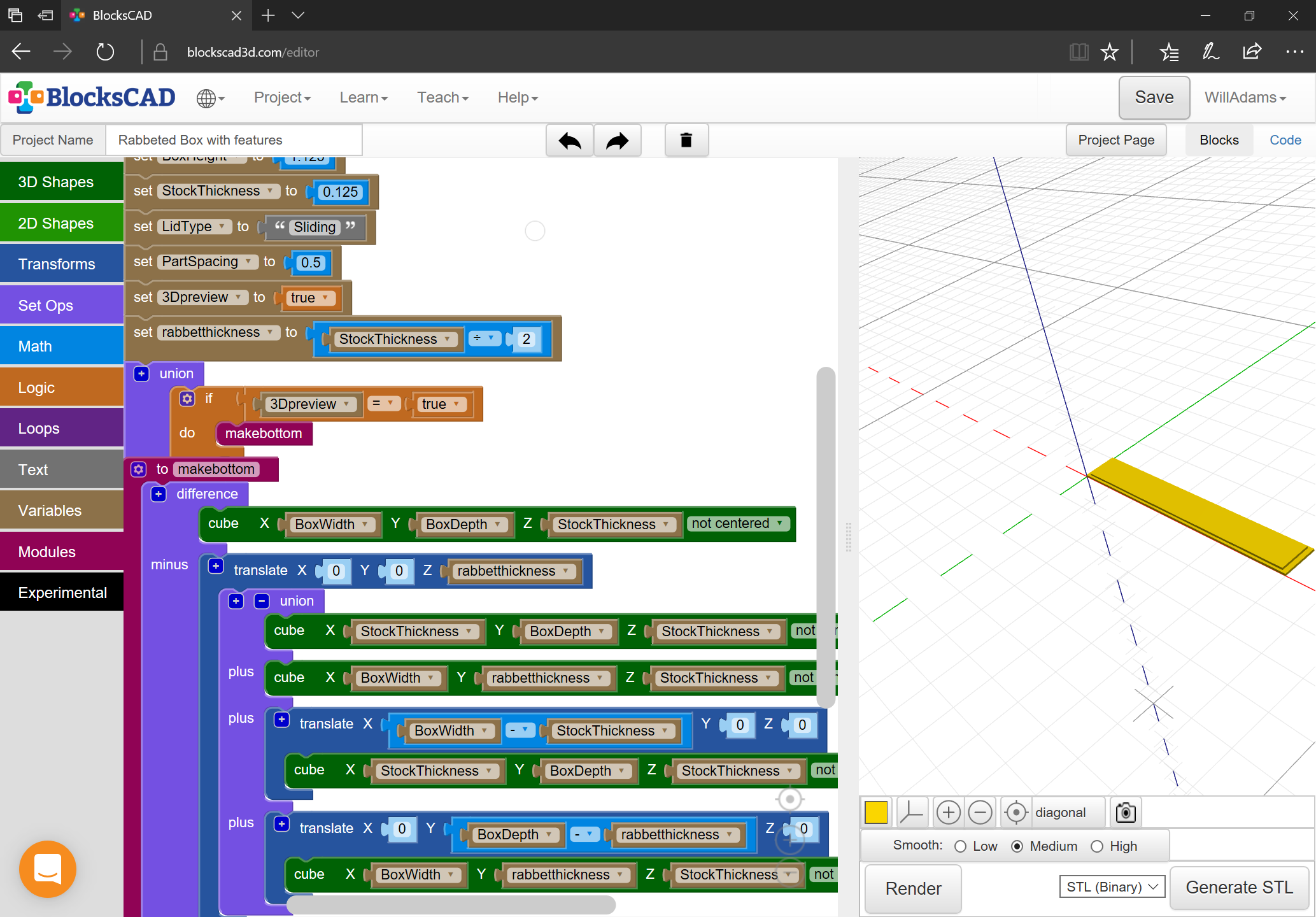
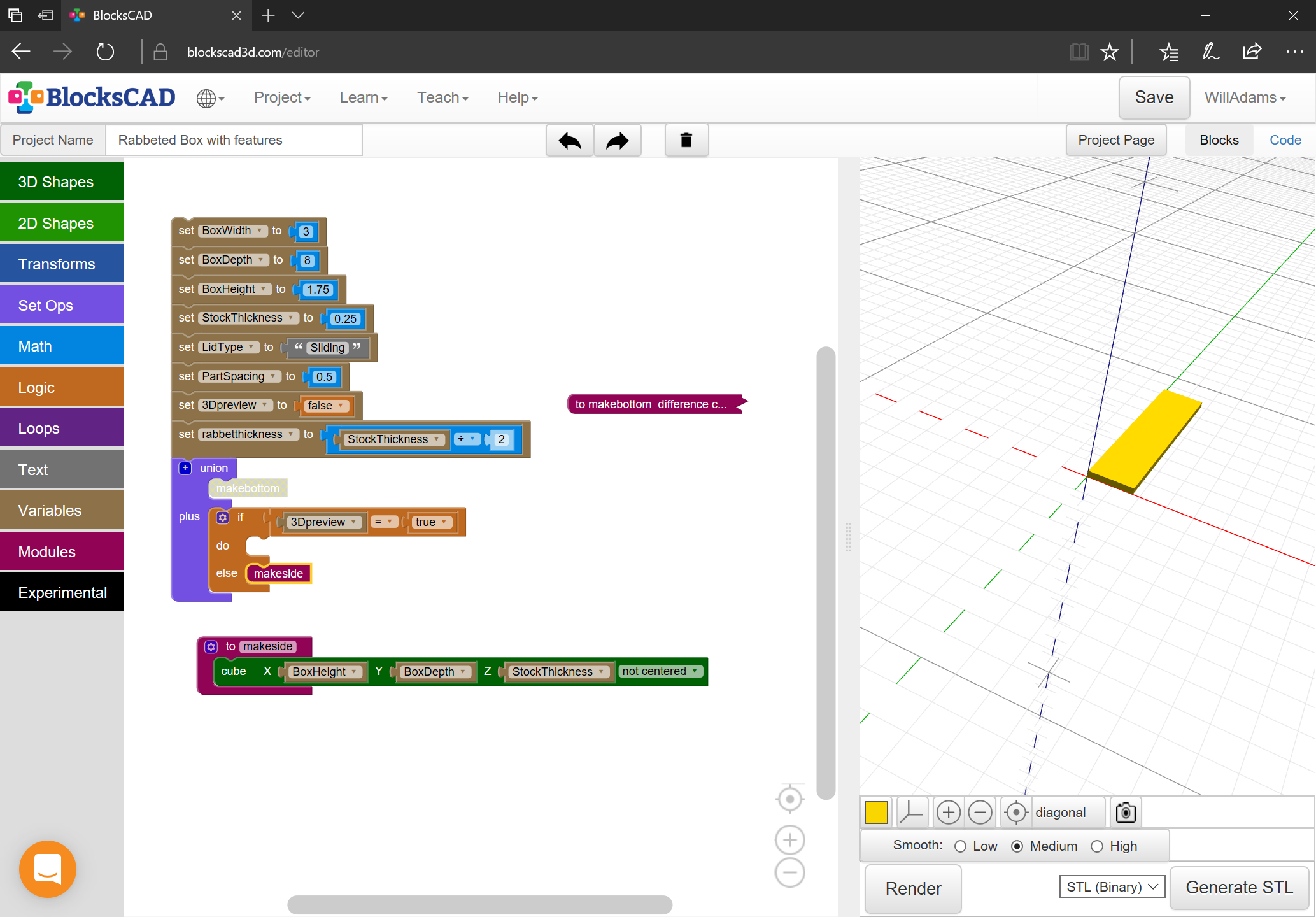
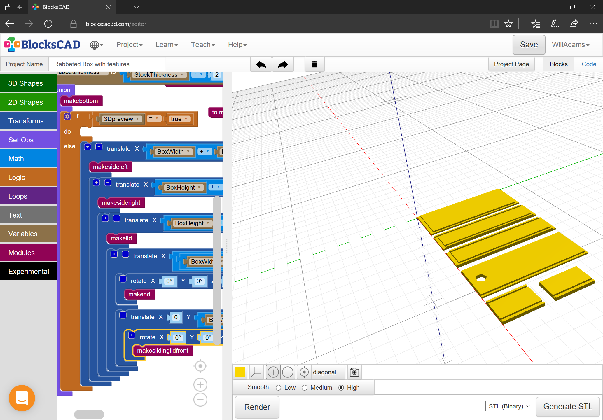
Here we will work out how to design this from scratch using either 3D modeling, or by drawing up in Carbide Create (or any other CAD or drawing program).

1 Like

We start in BlockSCAD, creating variables for the dimensions:

  • BoxWidth
  • BoxDepth
  • BoxHeight
  • StockThickness

and features:

  • LidType
    • None
    • Sliding

as well as interface options:

  • PartSpacing
  • 3Dpreview

(which will be added to or adjusted at need, and it will be necessary to add additional bookkeeping/convenience variables which will be all lowercase)

1 Like

First part is the bottom:

EDIT: Note that the dimensions for the bottom should be inset in both dimensions — see correct files further down.

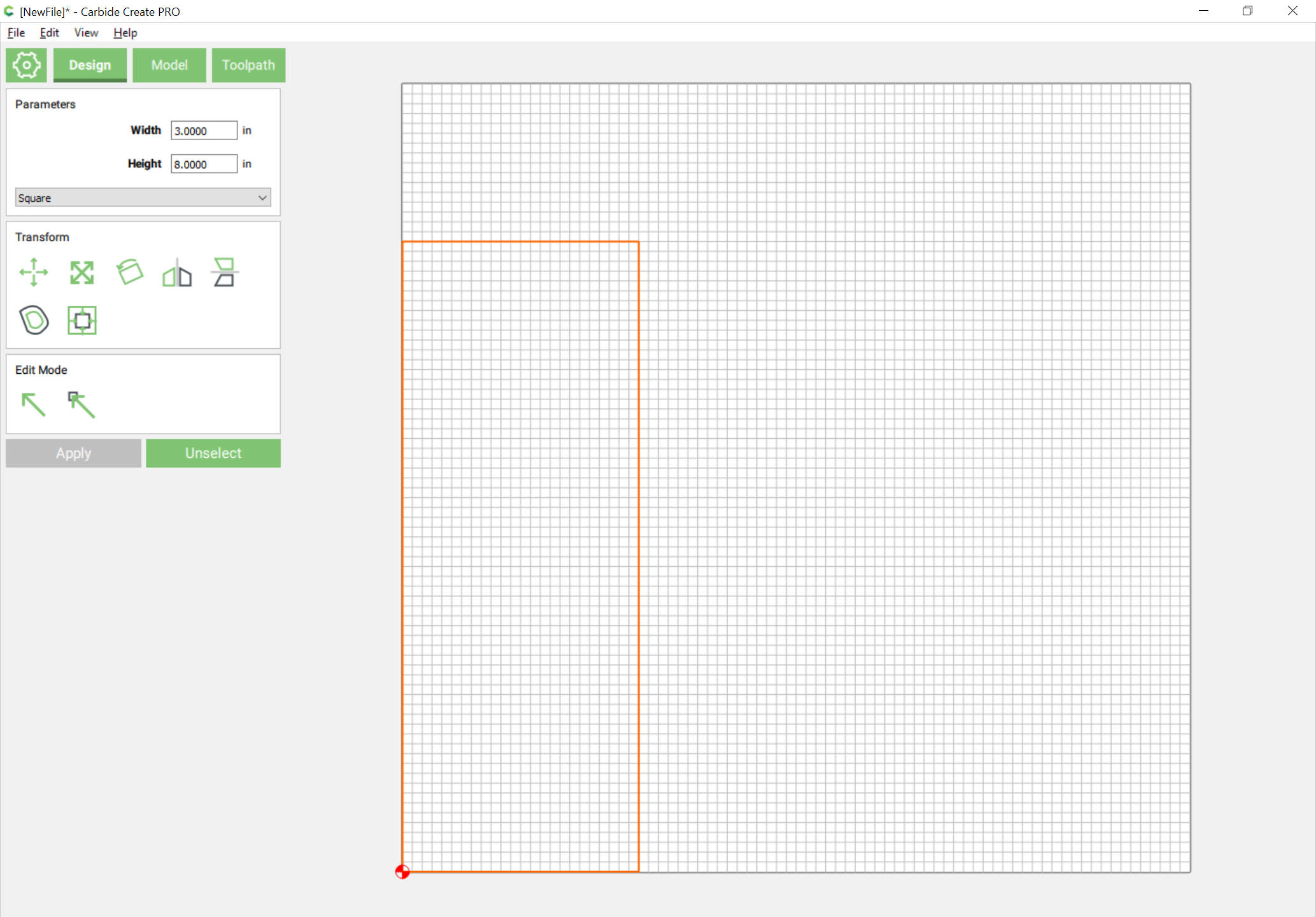
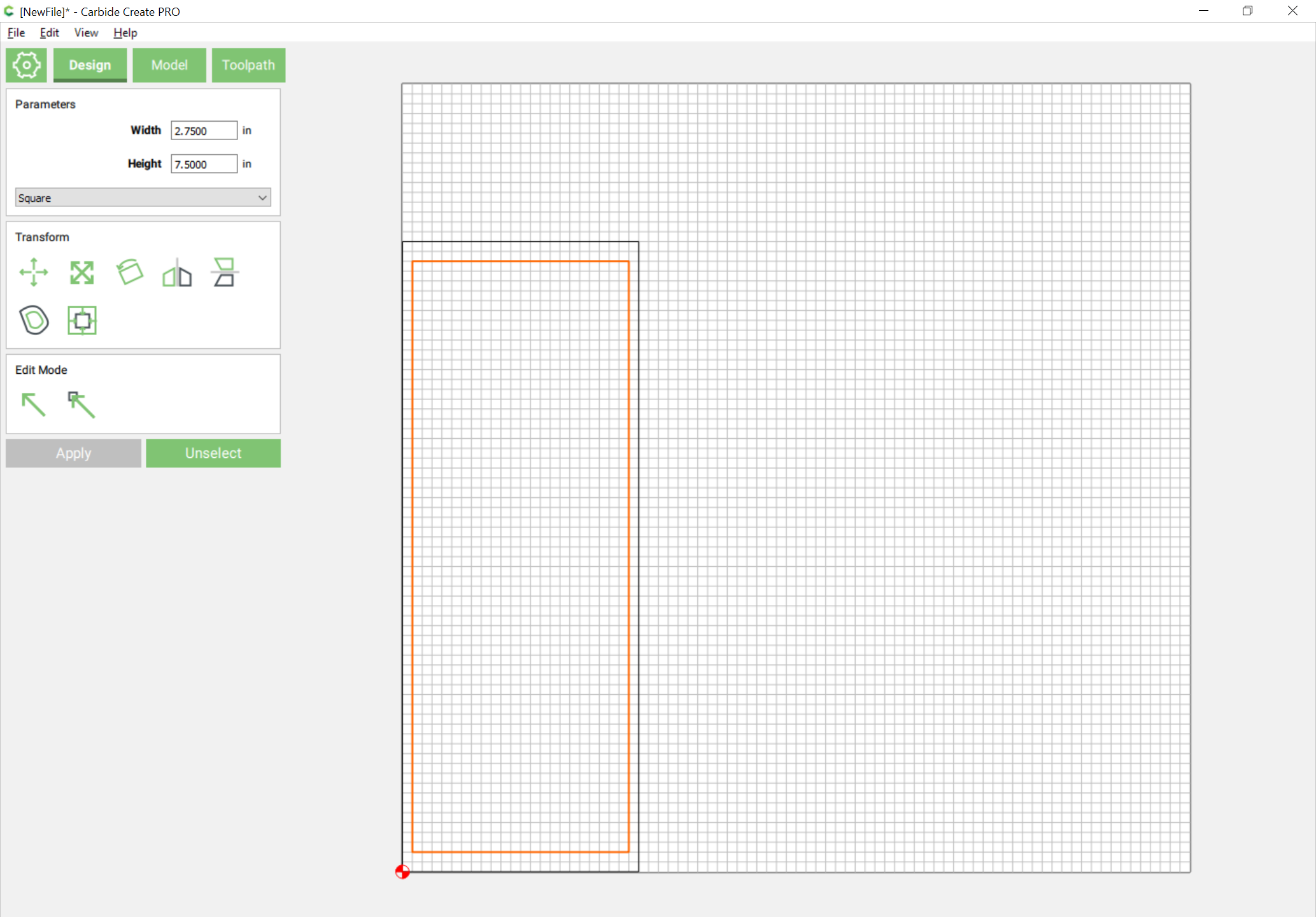
This is easily drawn in Carbide Create as a pair of nested rectangles — one the width and depth of the box, the other width less twice the stockthickness, depth less the stockthickness.

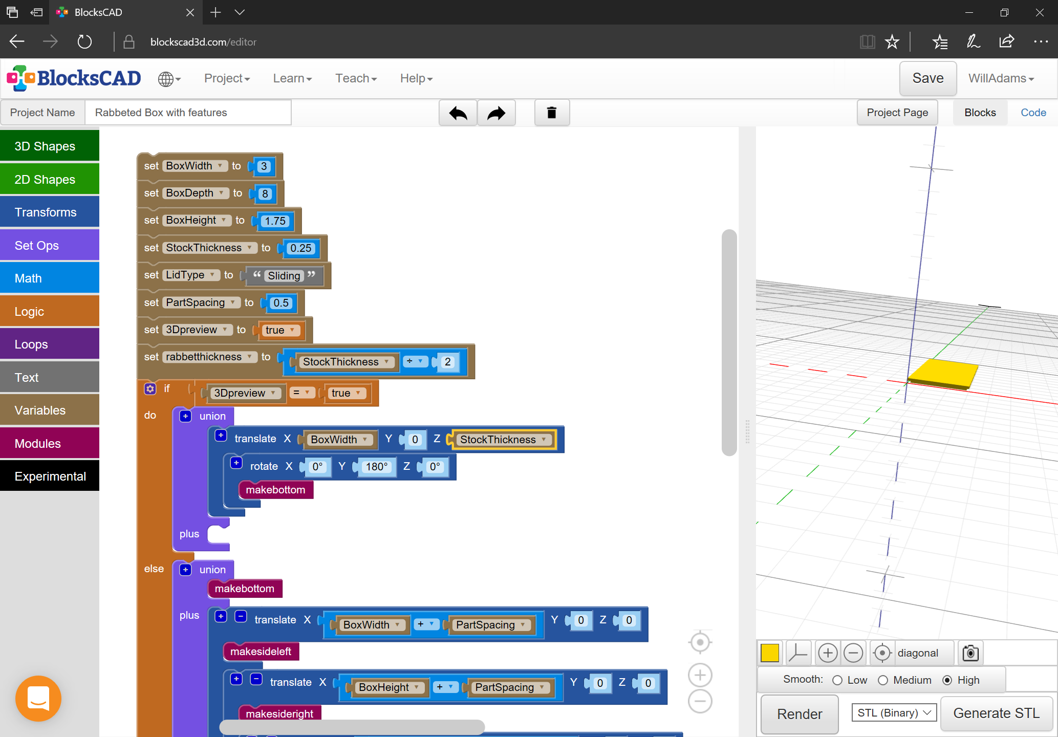
We will use the following dimensions for the first iteration of the box:

  • Width == 3 inches
  • Depth == 8 inches
  • Height == 1.75 inches
  • StockThickness == 0.25 inches
  • LidType == Sliding

so we begin by drawing:

and then add:

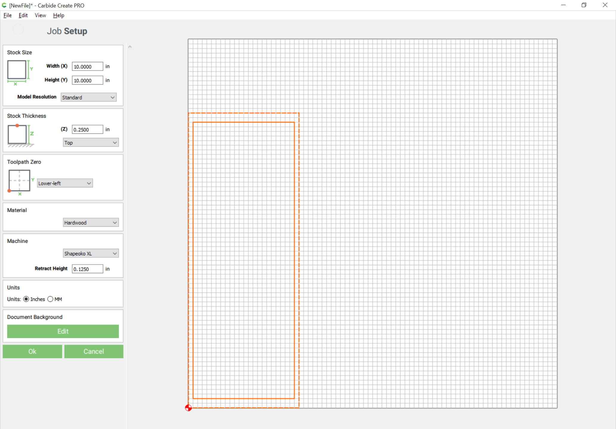
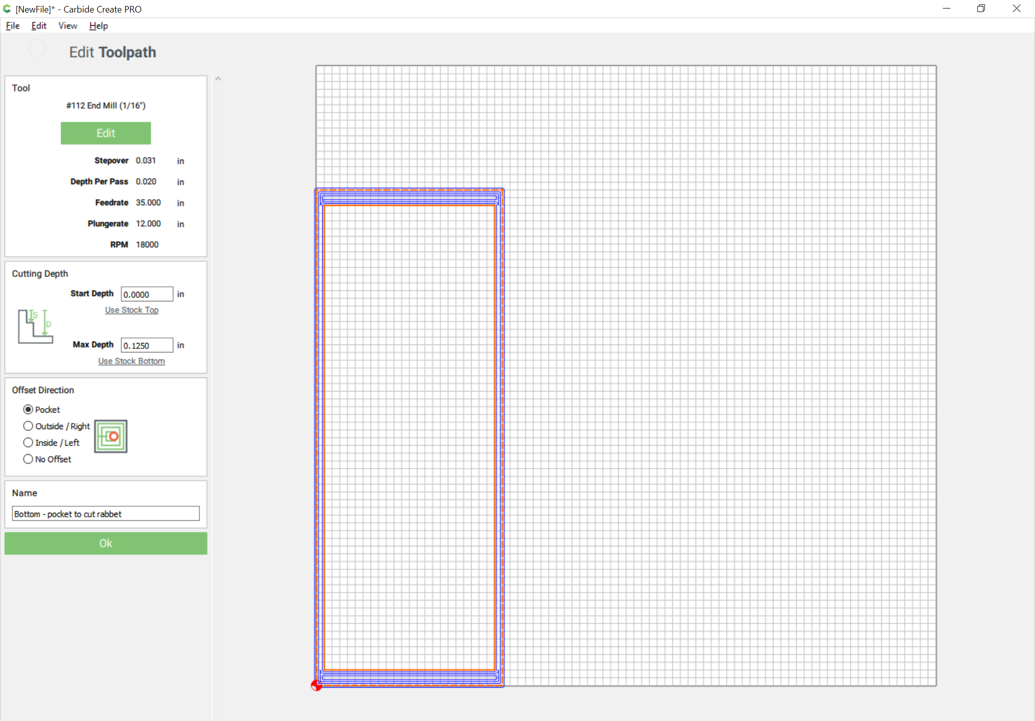
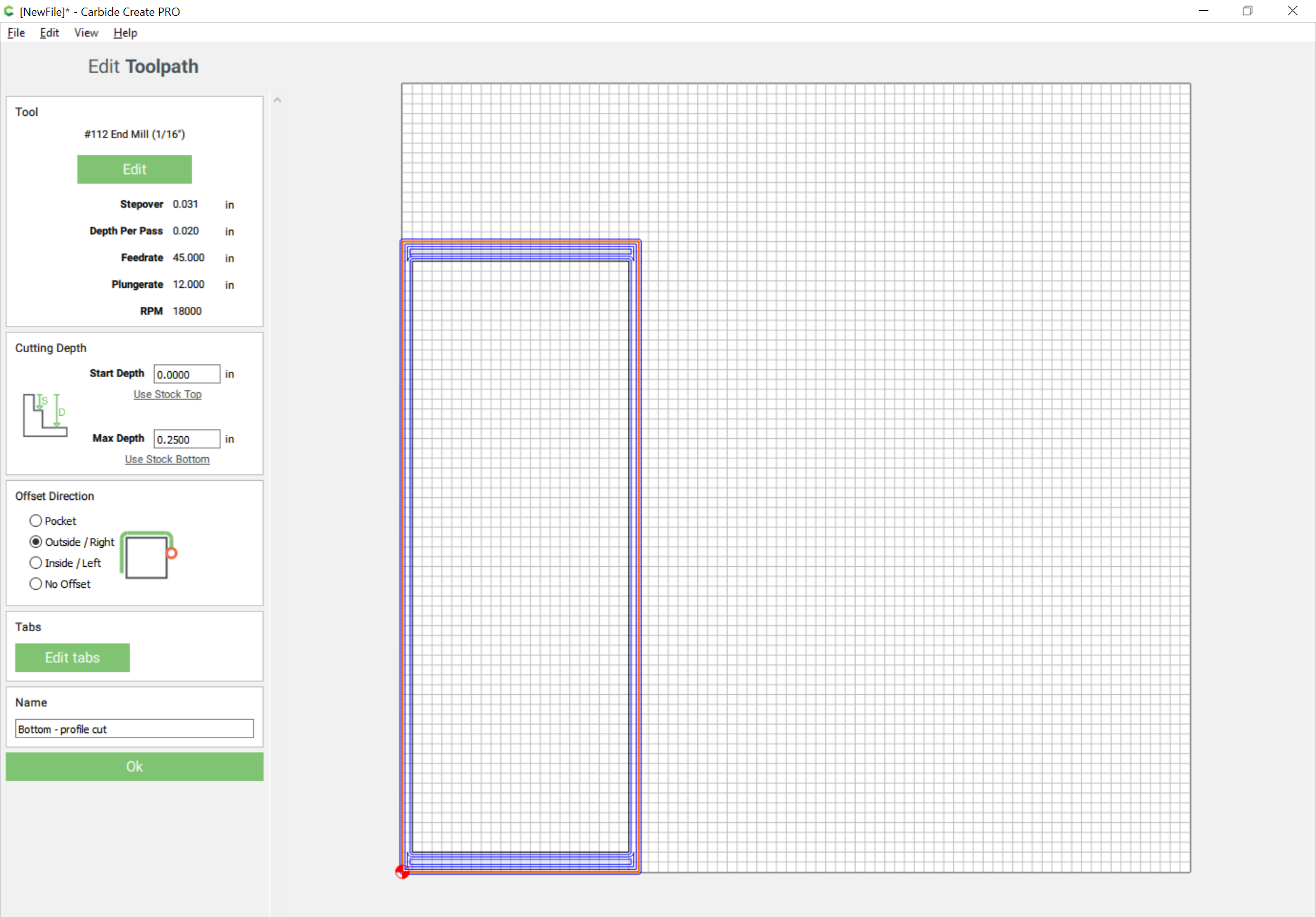
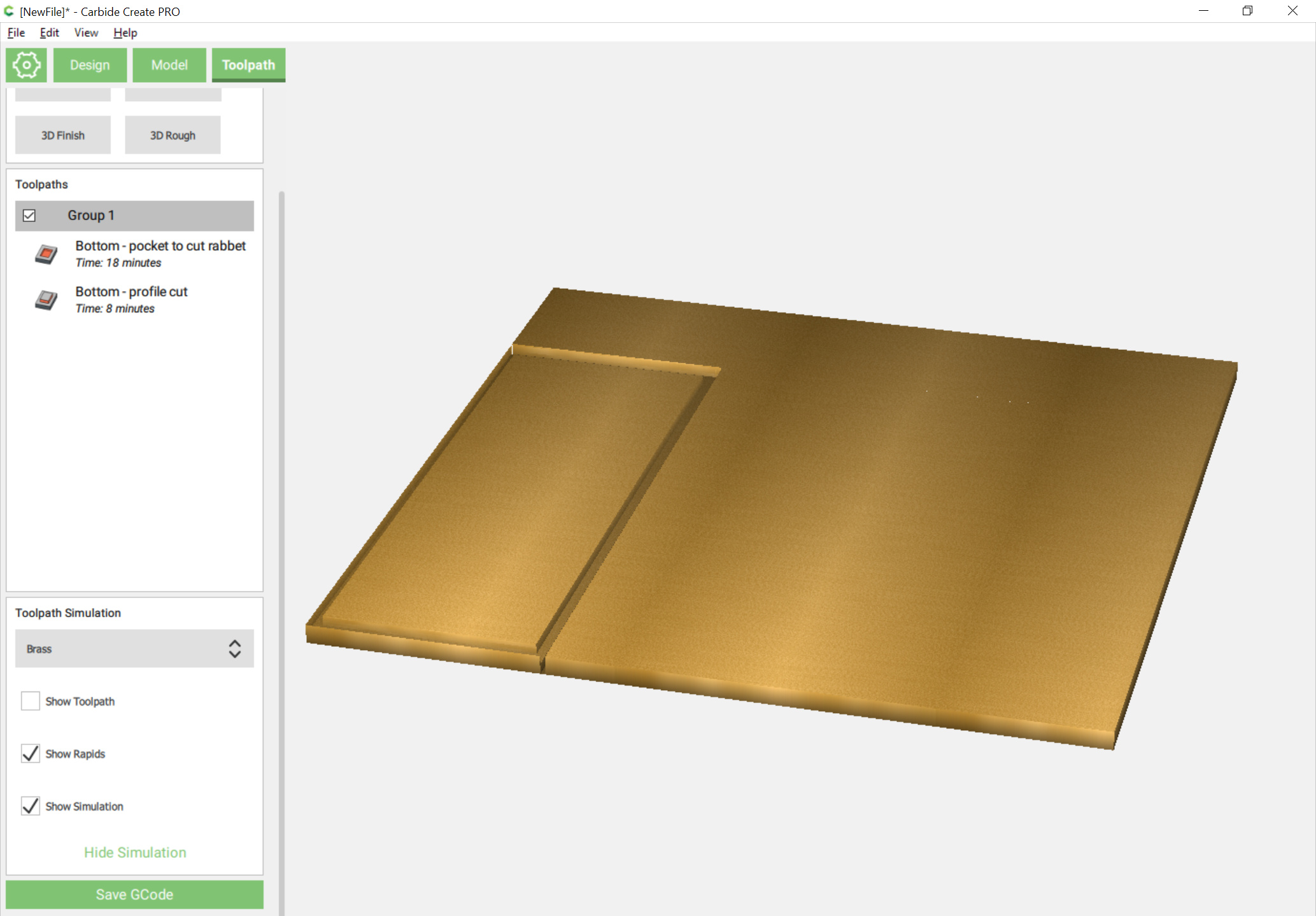
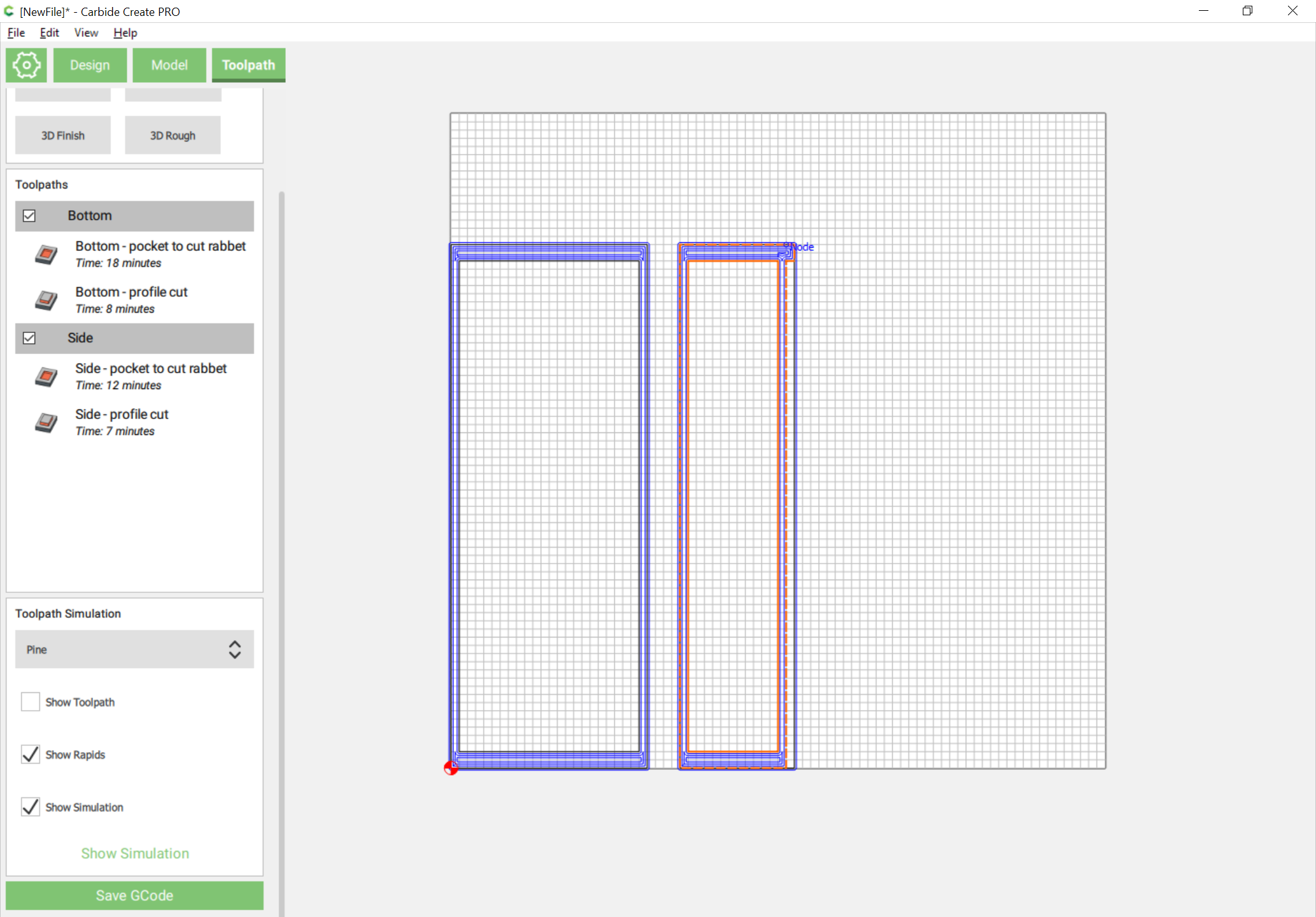
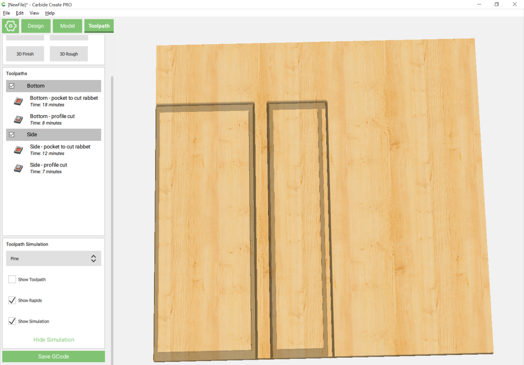
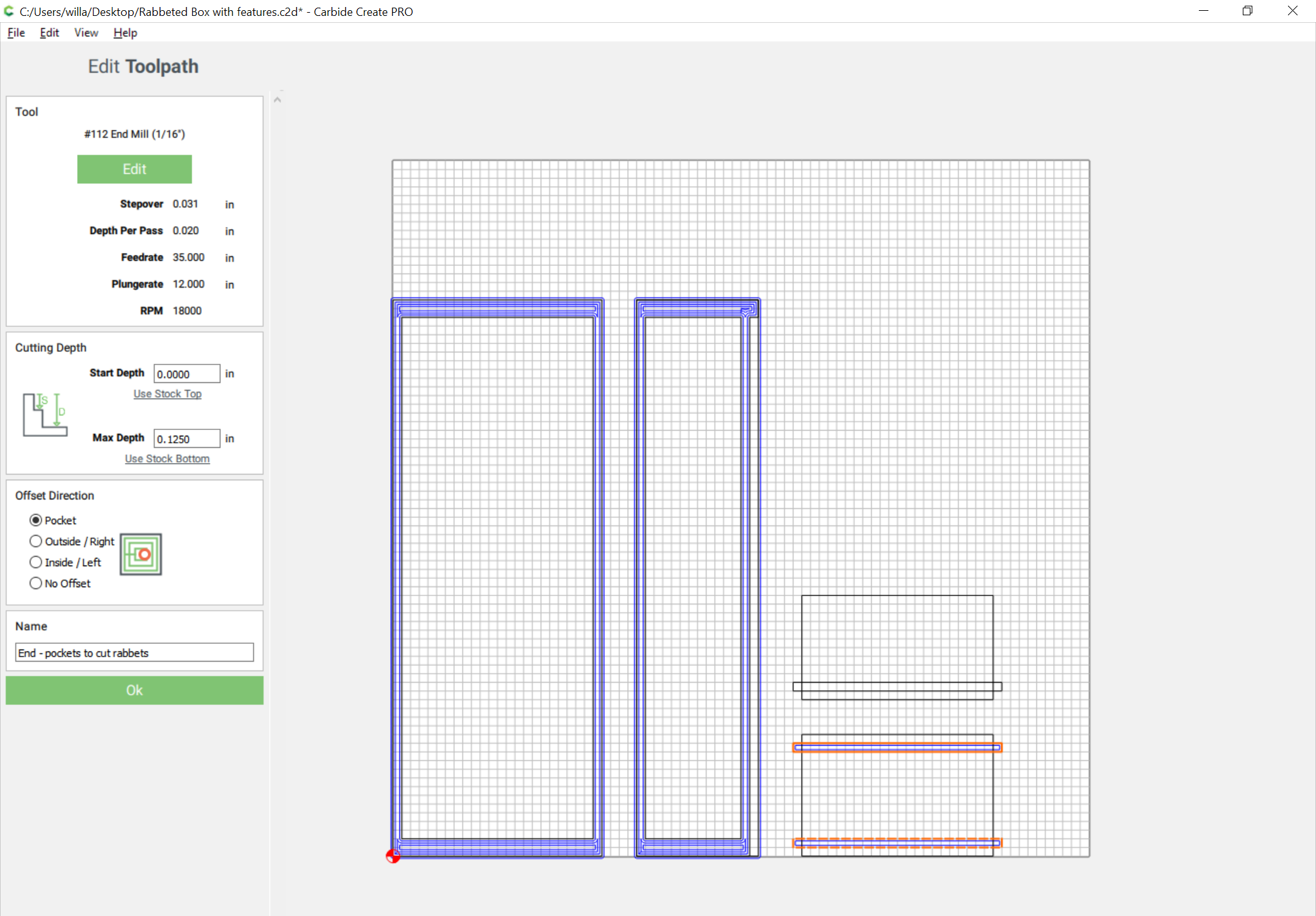
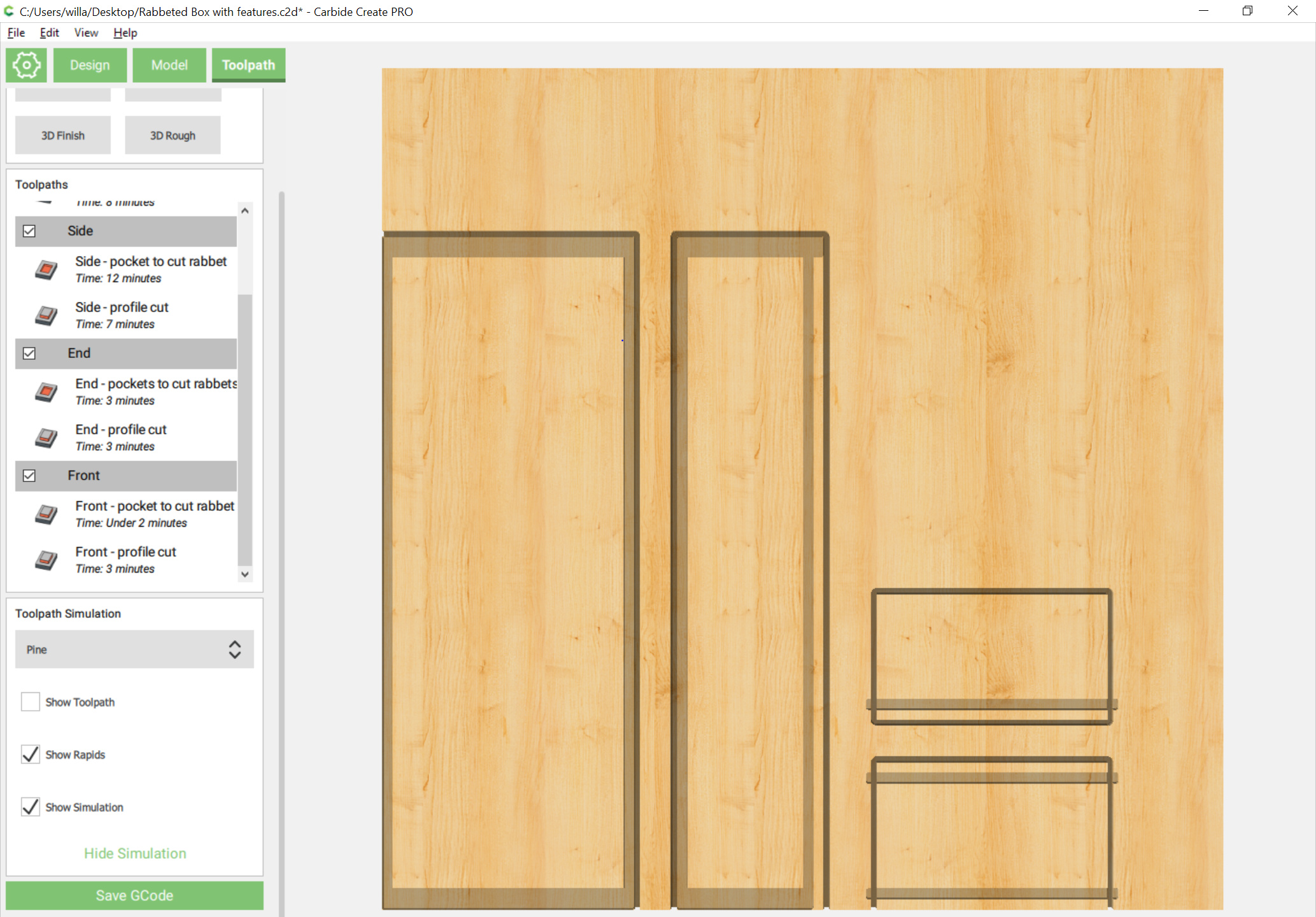
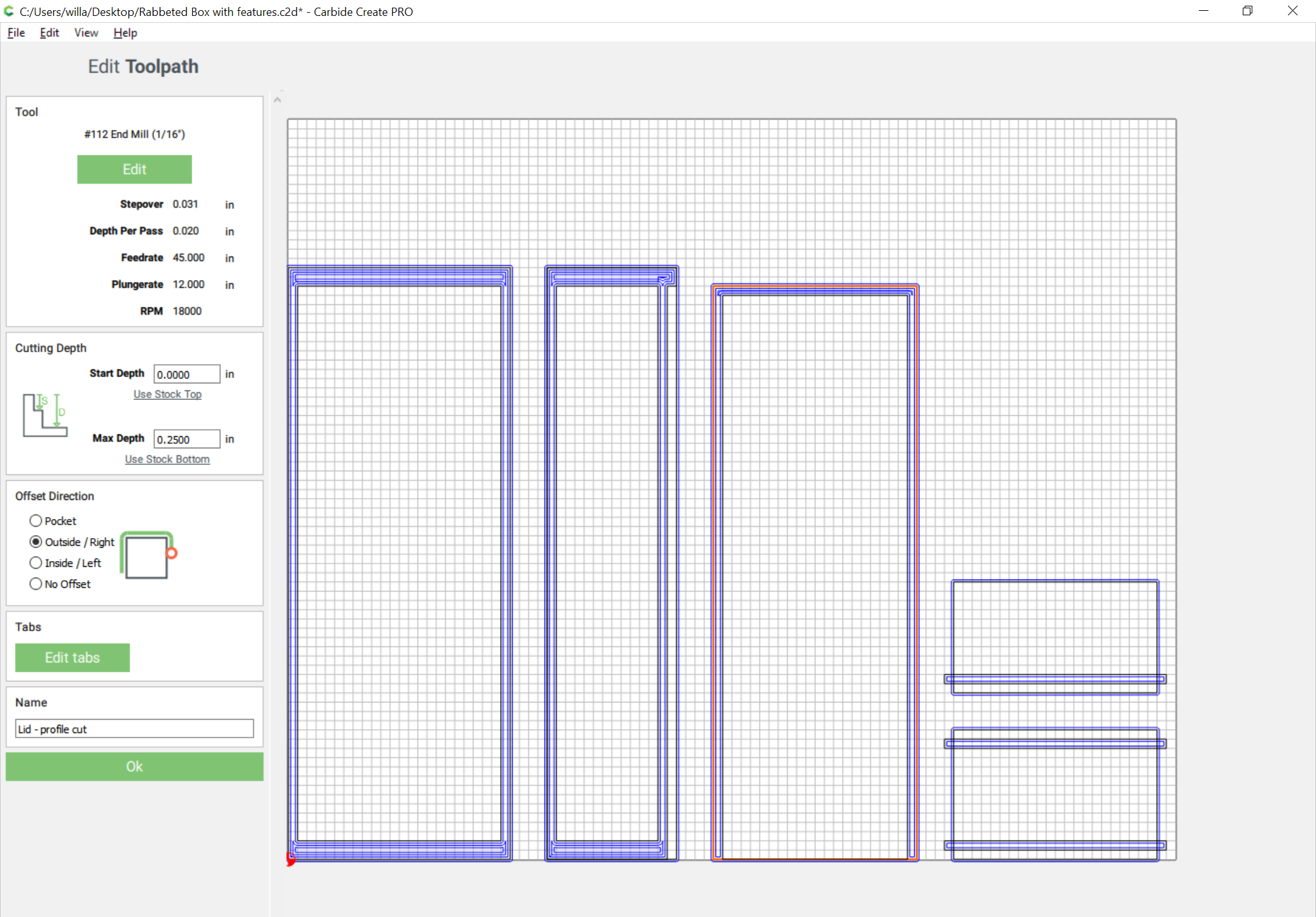
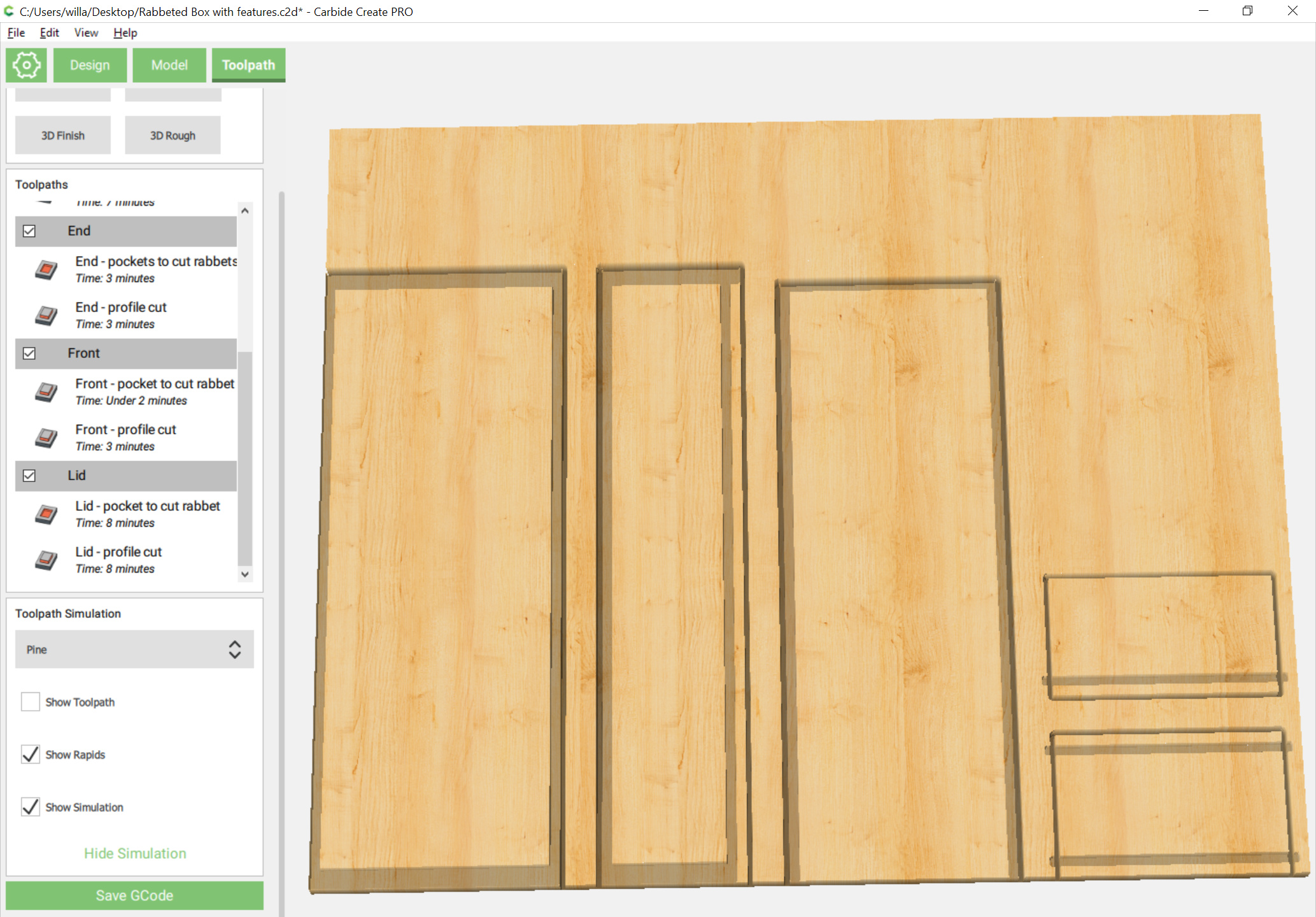
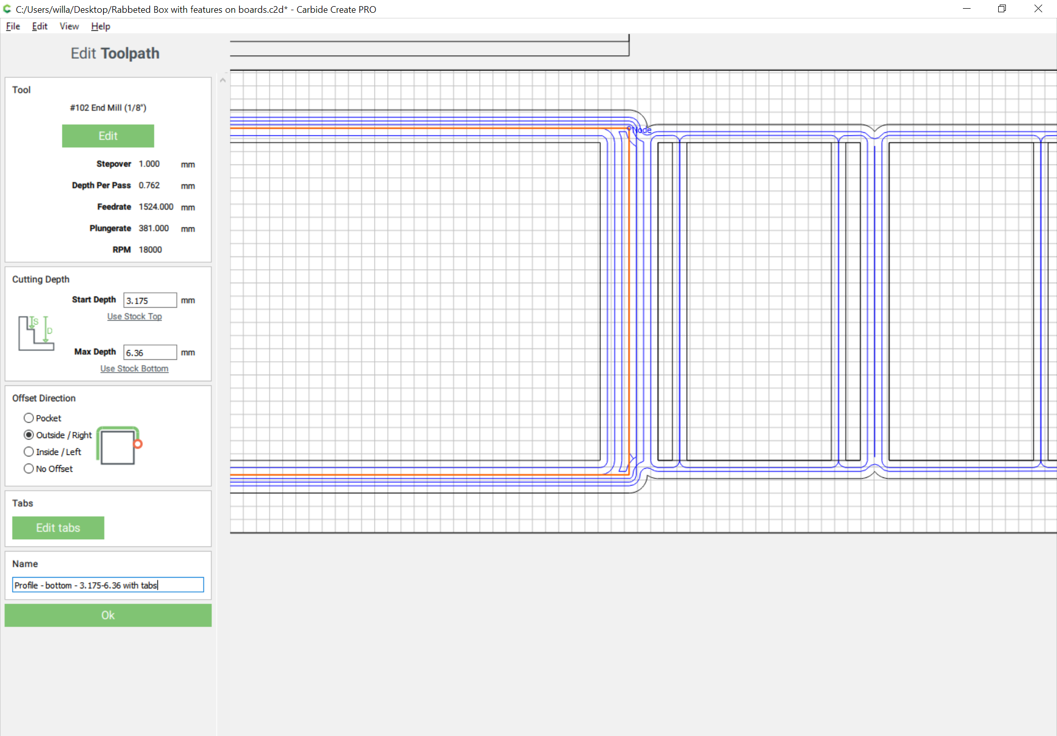
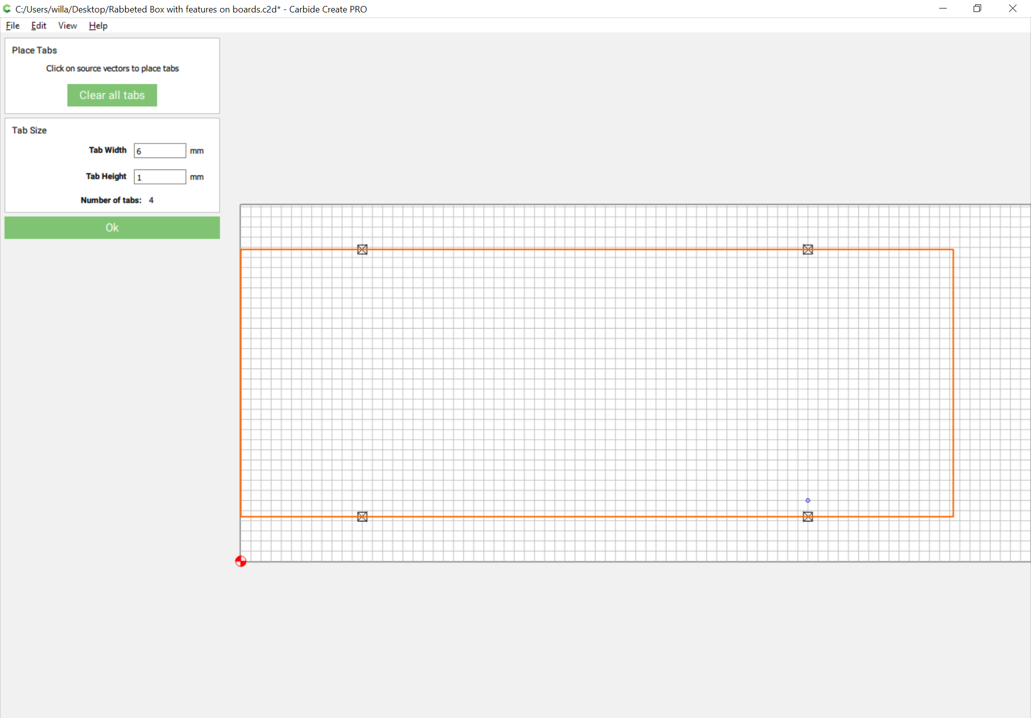
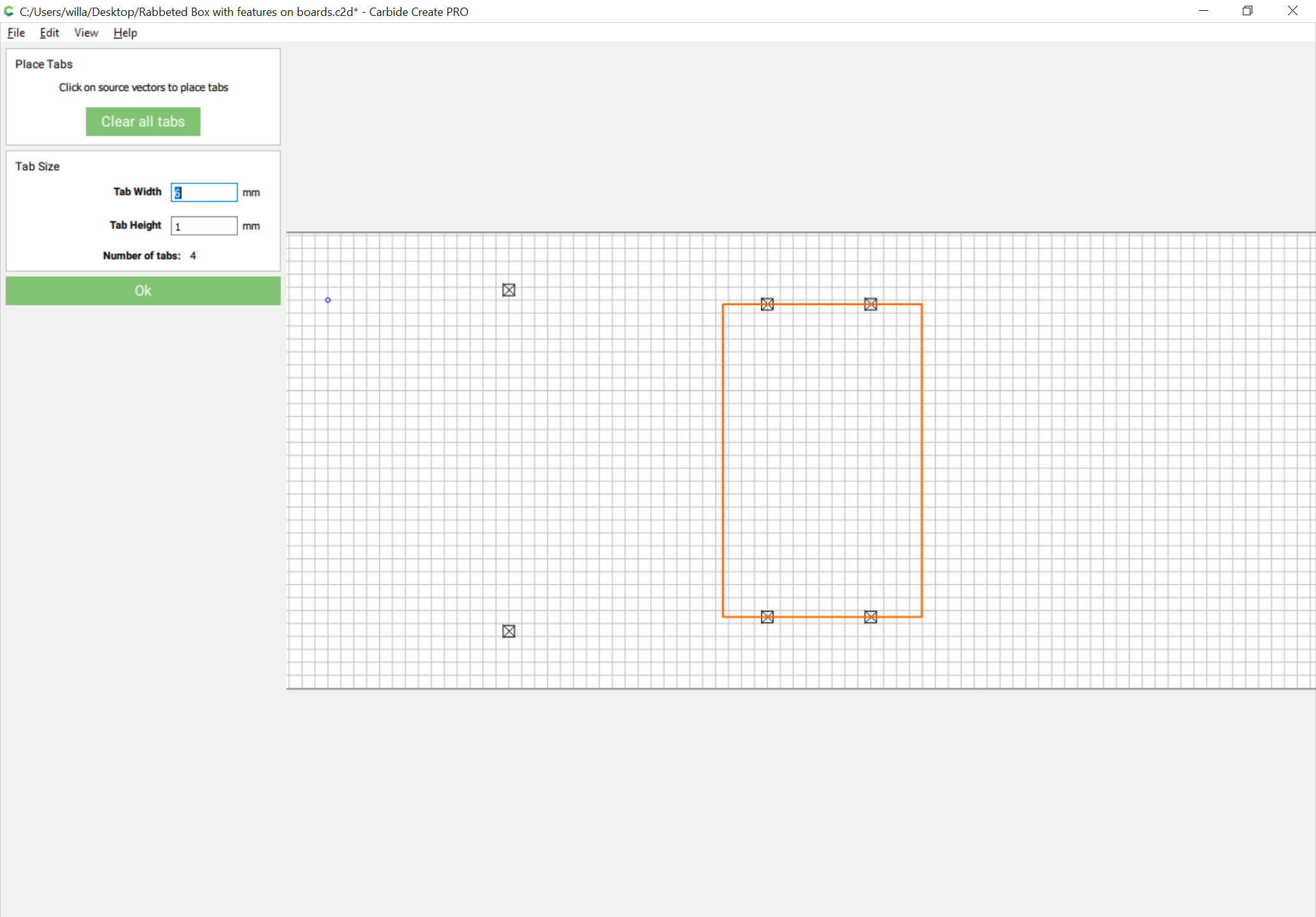
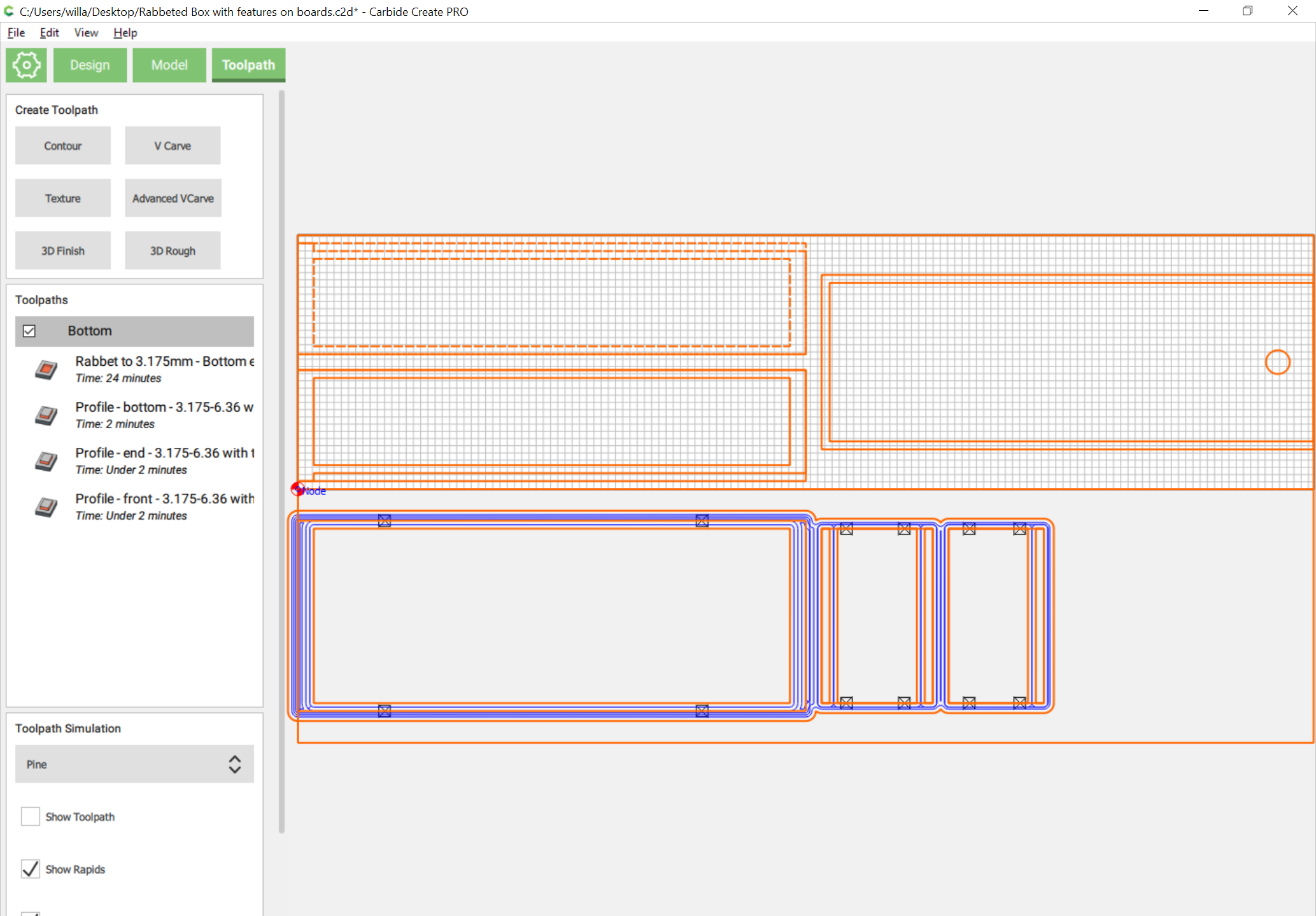
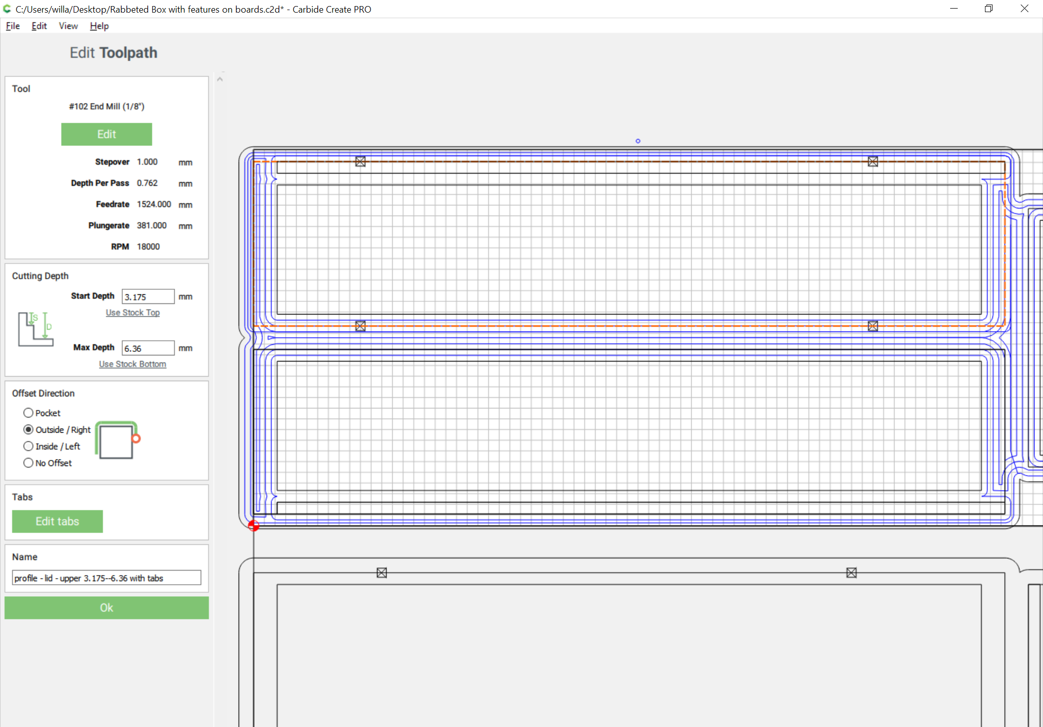
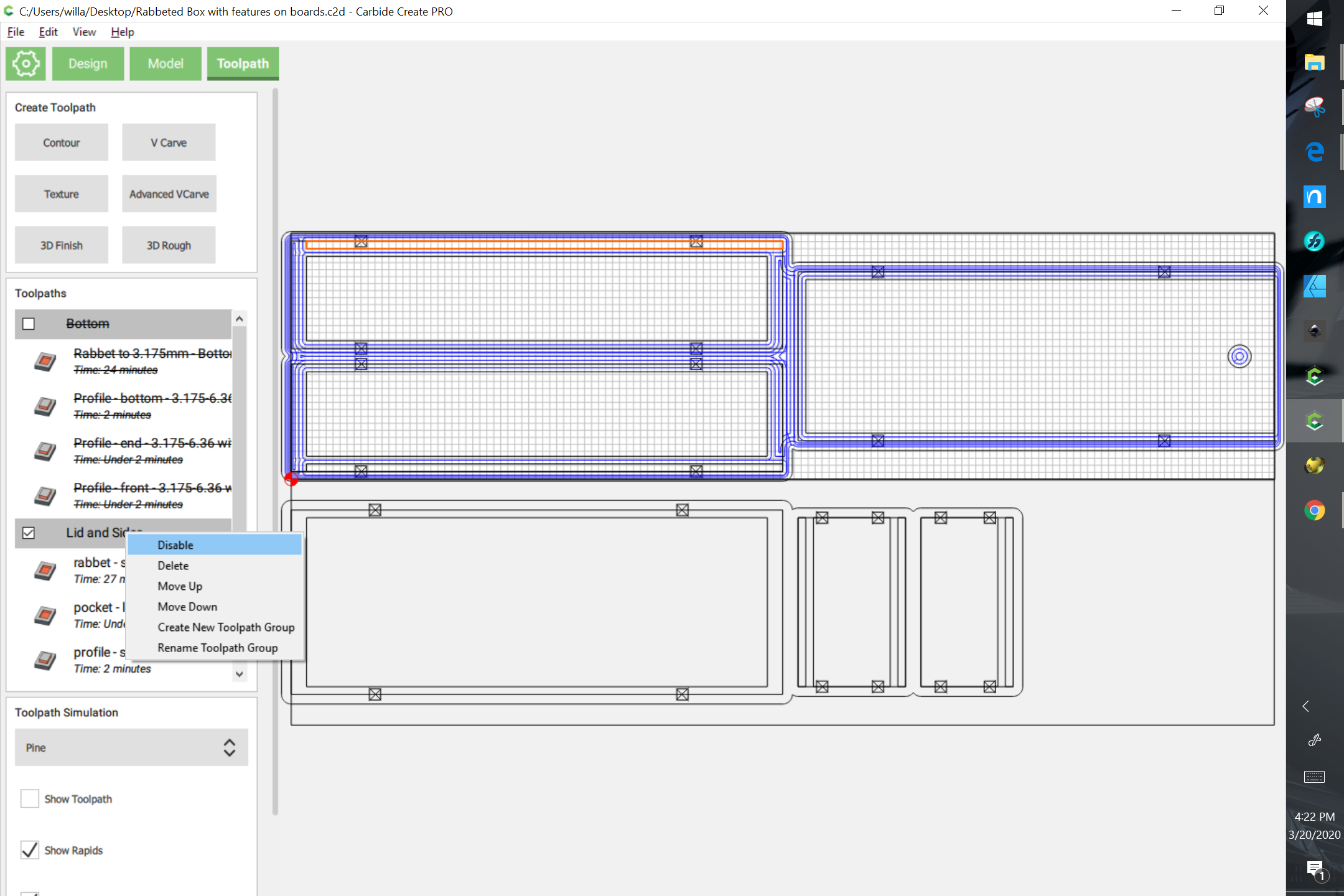
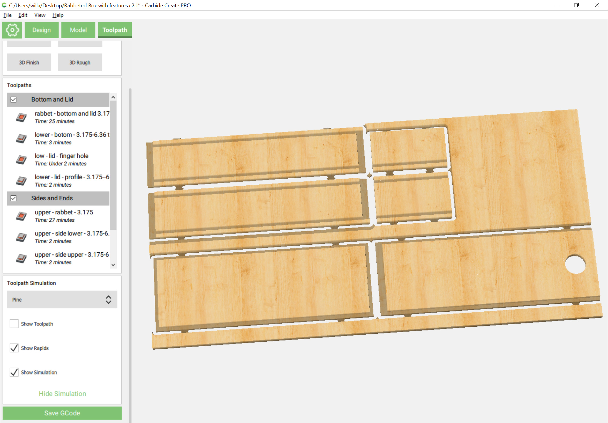
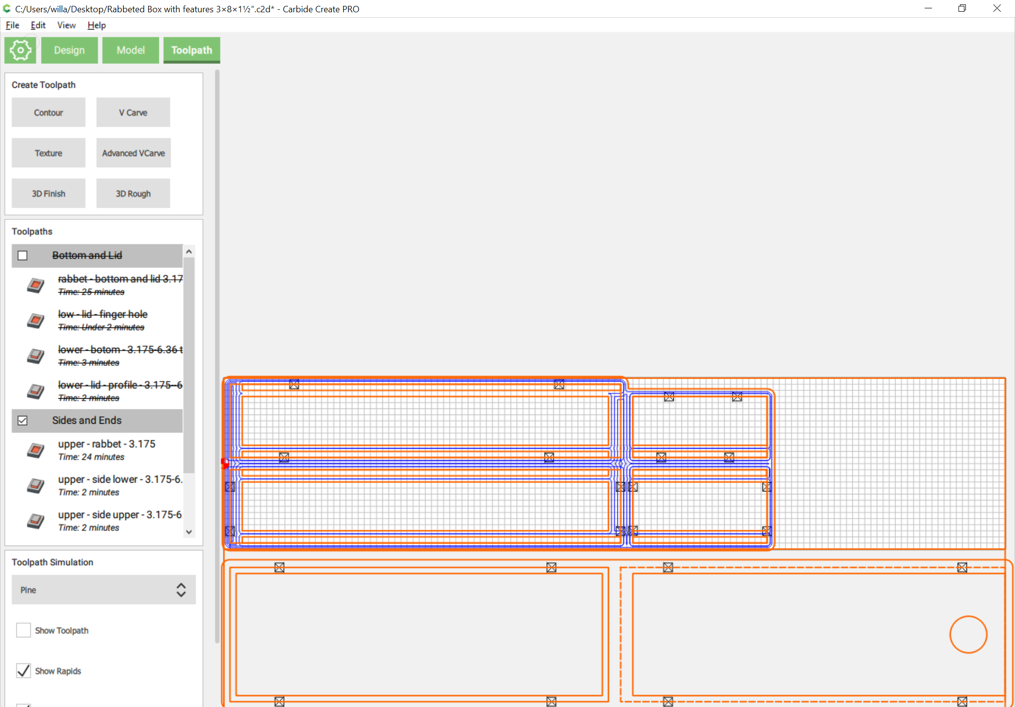
Toolpath assignment will be the bare minimum necessary to cut parts out — adding tabs or additional geometry to cut as a pocket down to tab depth will be left as an exercise for the reader (Note that doing so is pretty much required to actually cut this in a reasonable period of time, since for expediency a very small endmill will be used).

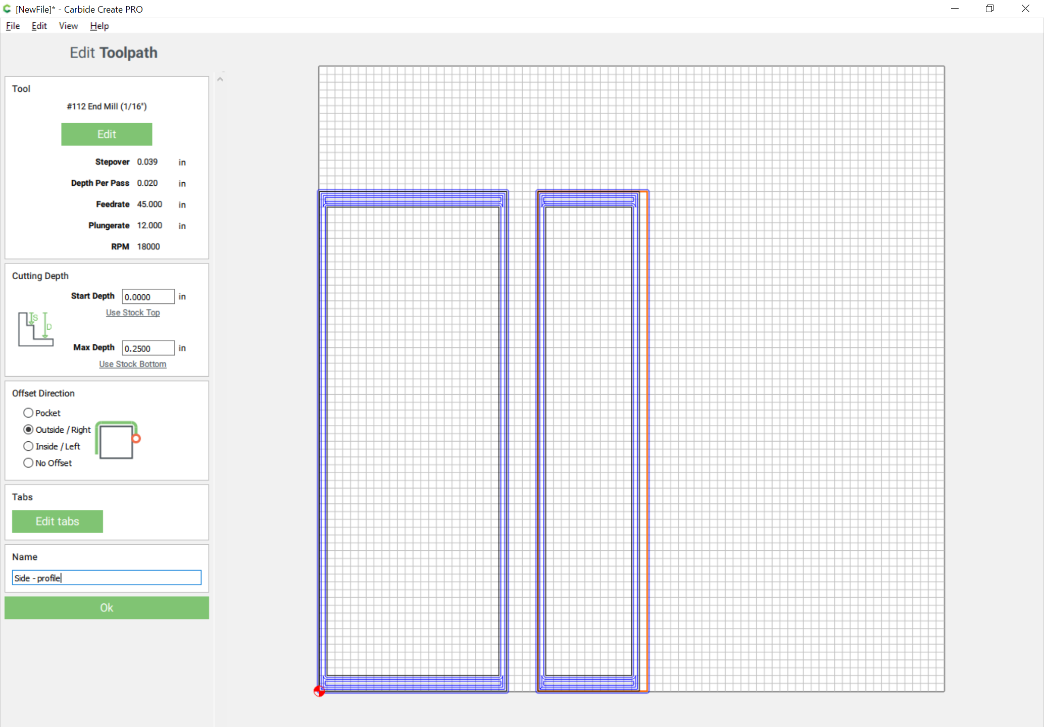
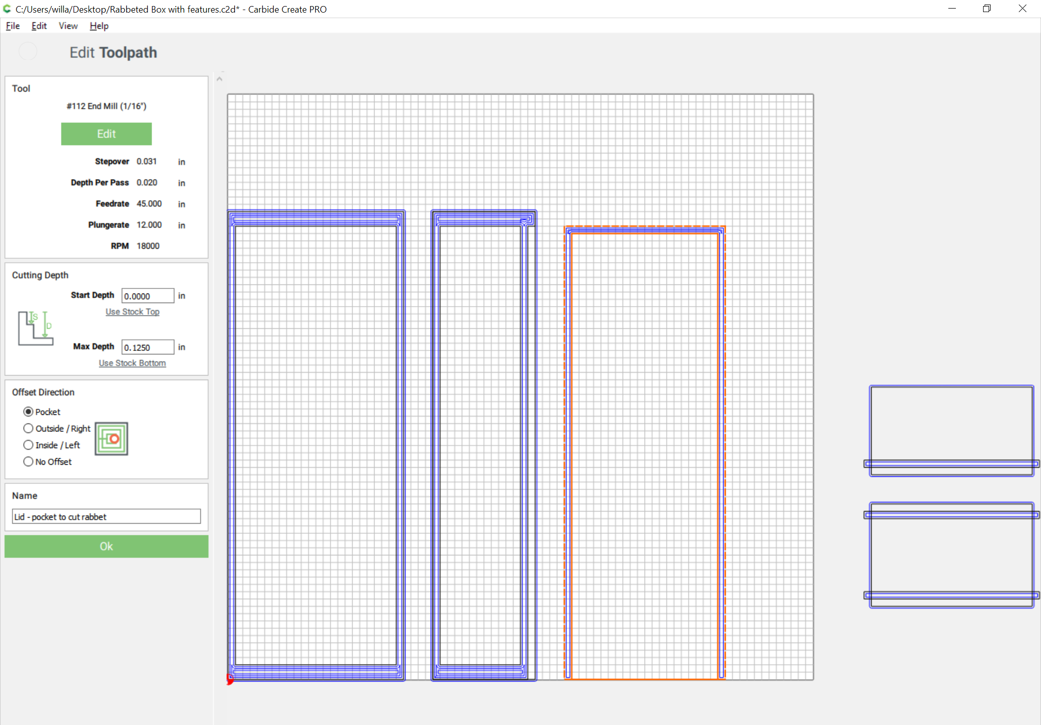
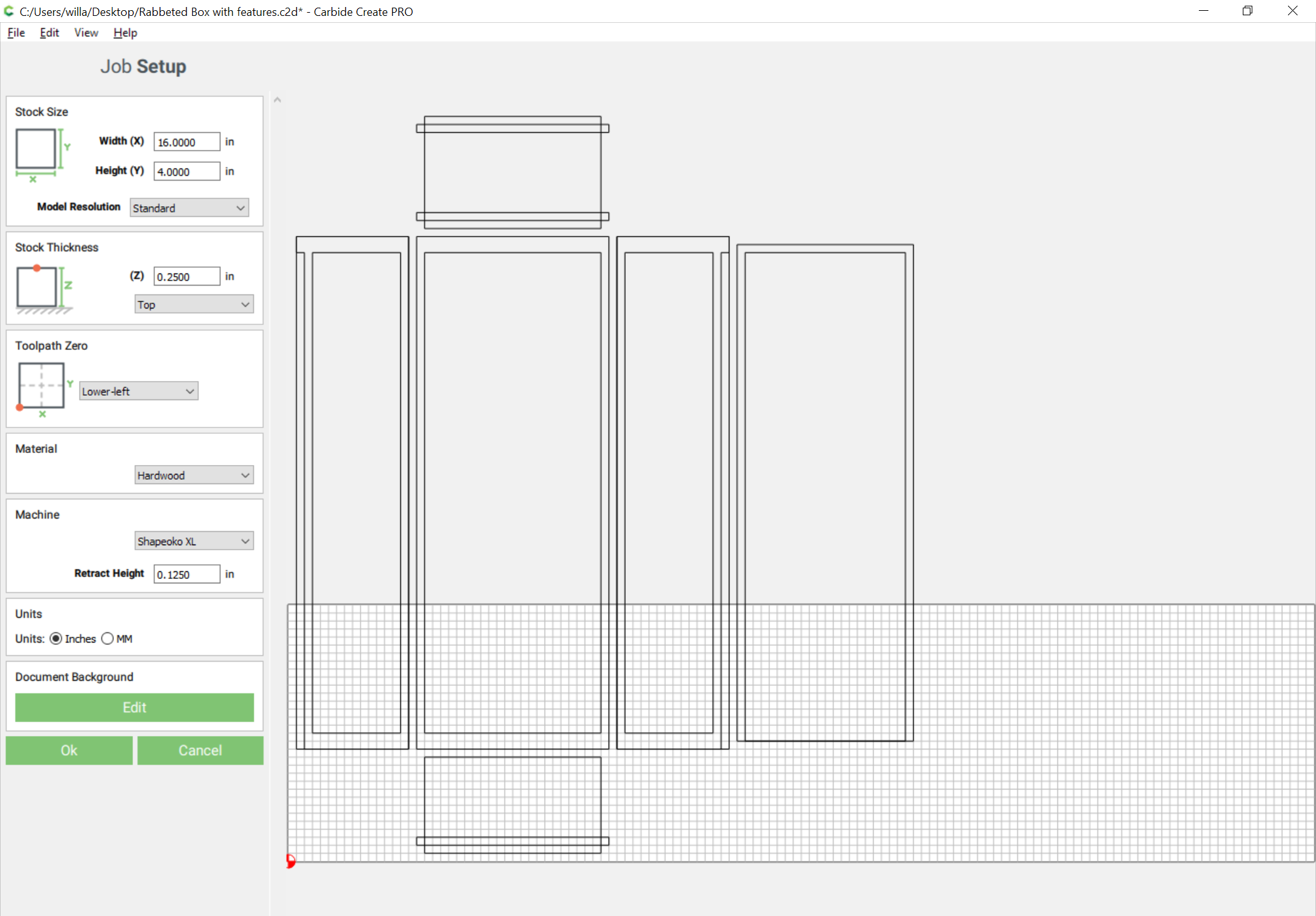
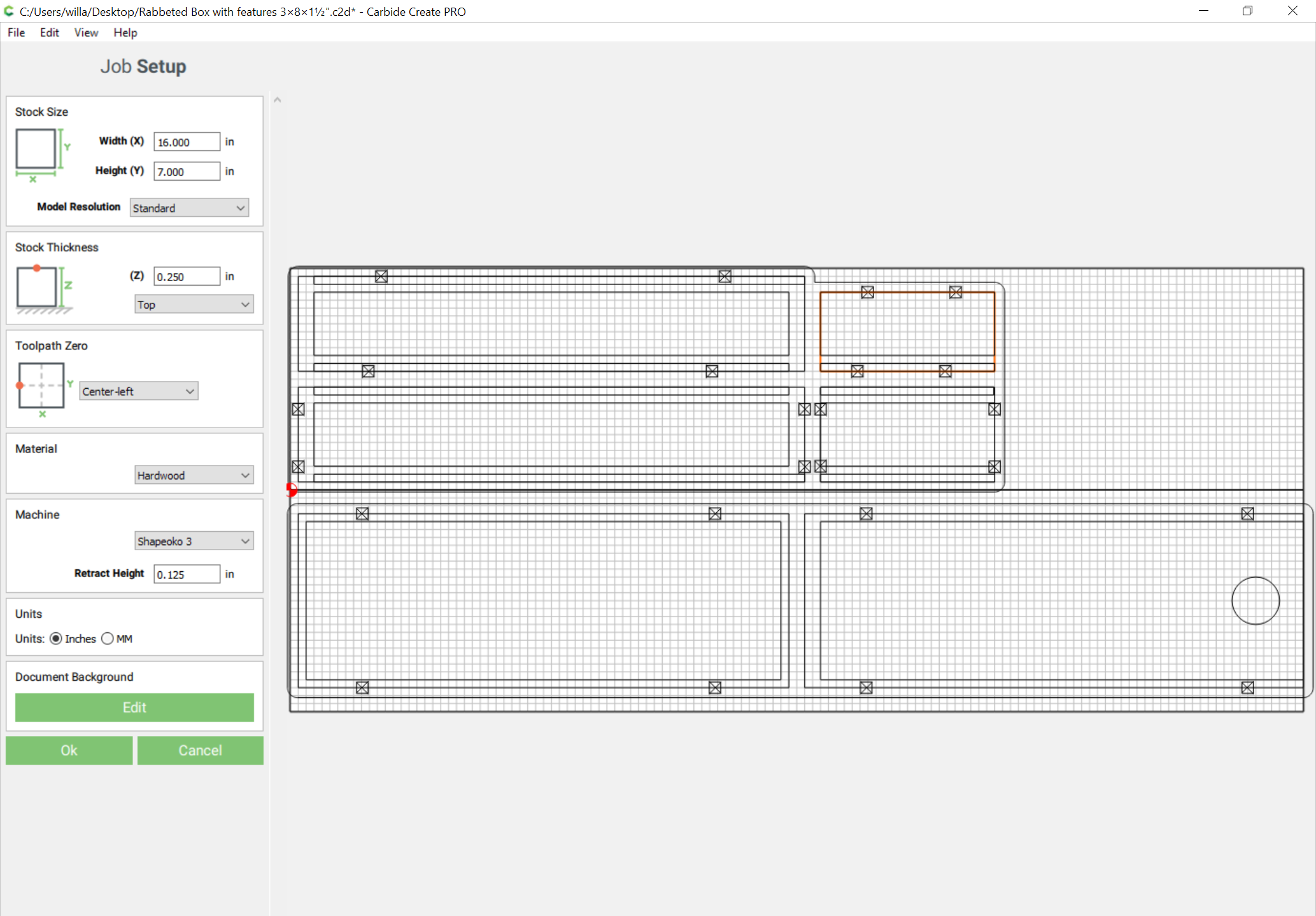
Naturally job setup is for the StockThickness of 0.25in:

First the rabbet:

Then a profile to cut out the part:

which profiles as:

1 Like

Since the box is symmetrical, the sides are mirror images of each other, as wide as the box is high, as long as it is deep, and StockThickness:

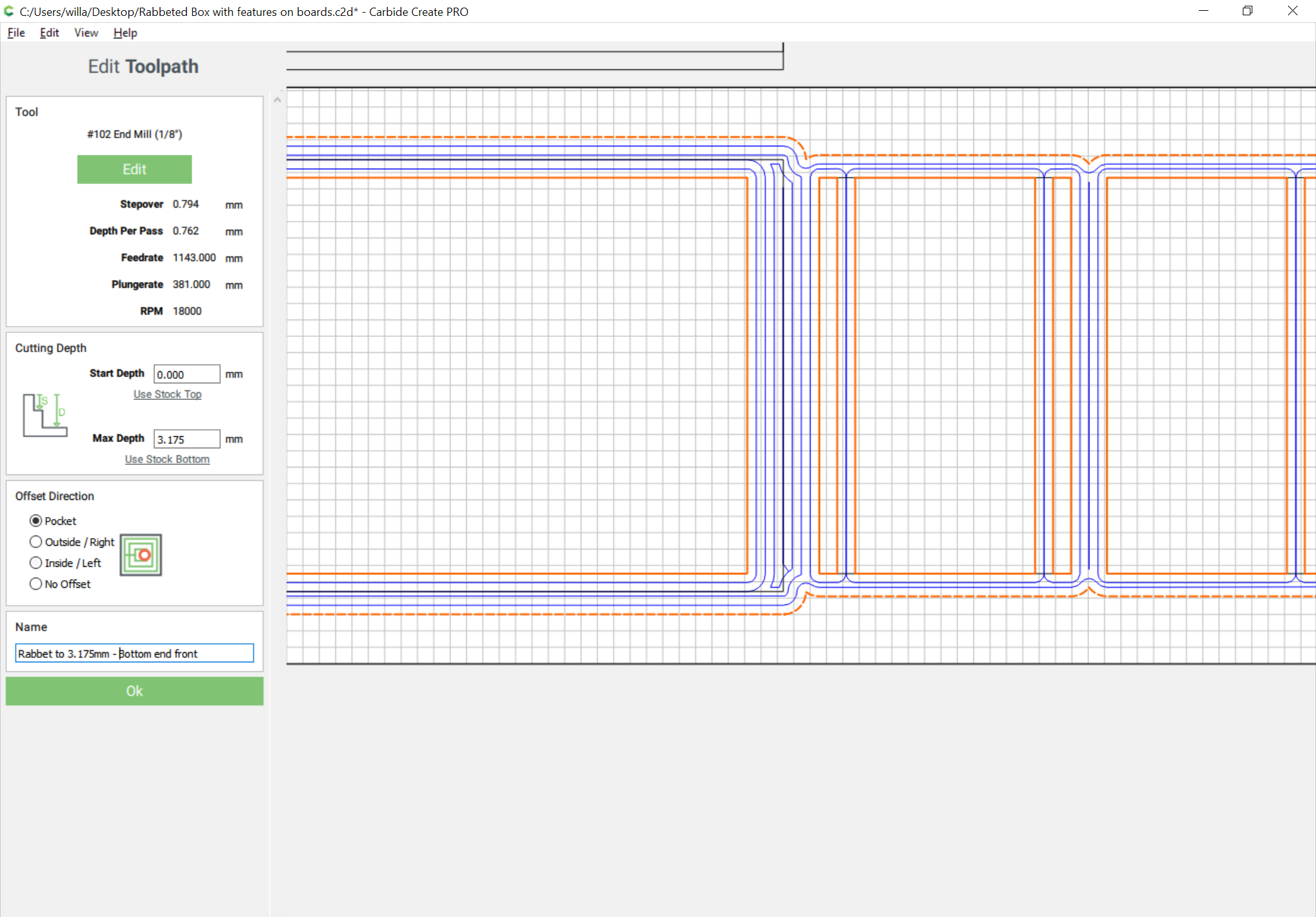
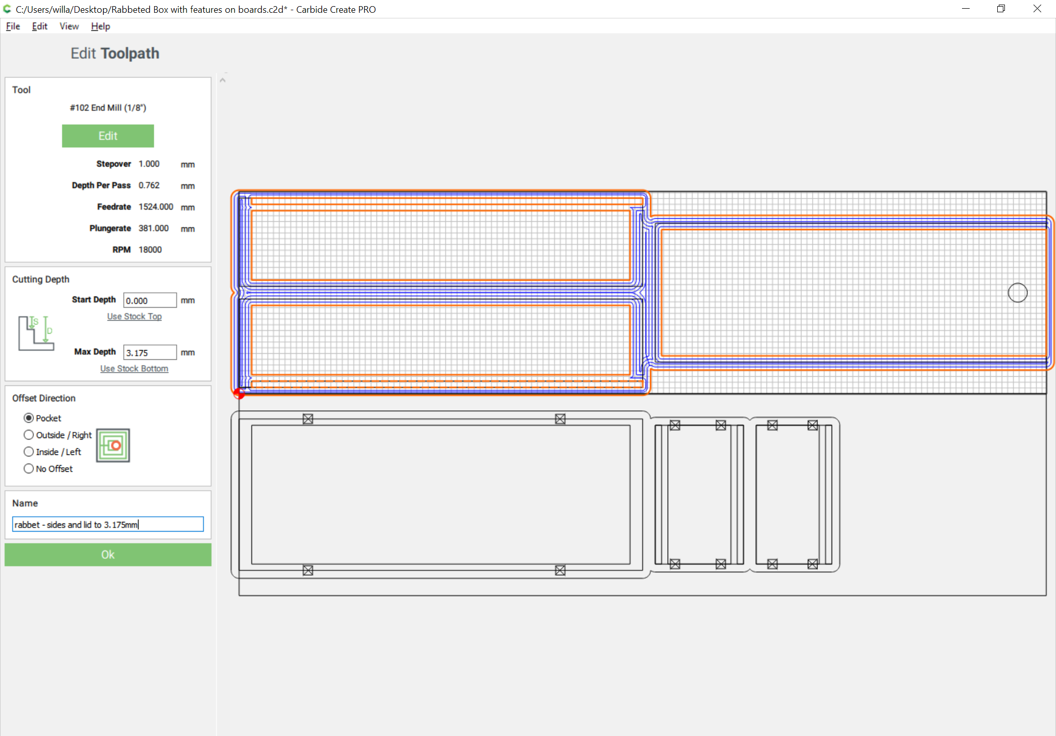
We need to remove half the depth of StockThickness at each end in a rabbet which allows for the full thickness of the ends (so again StockThickness), as well as cutting a full length rabbet for the bottom, and a stopped rabbet for the lid at the back of the box.

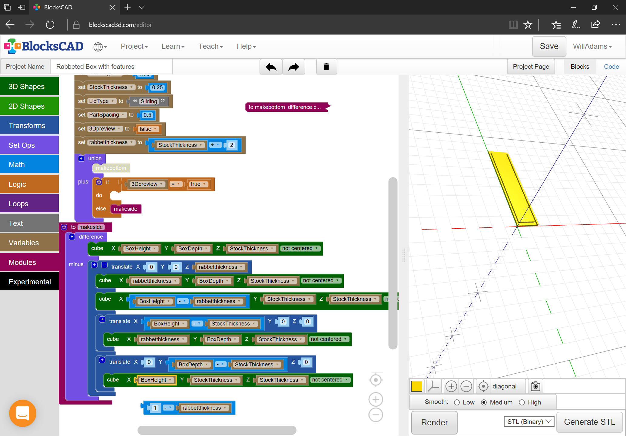
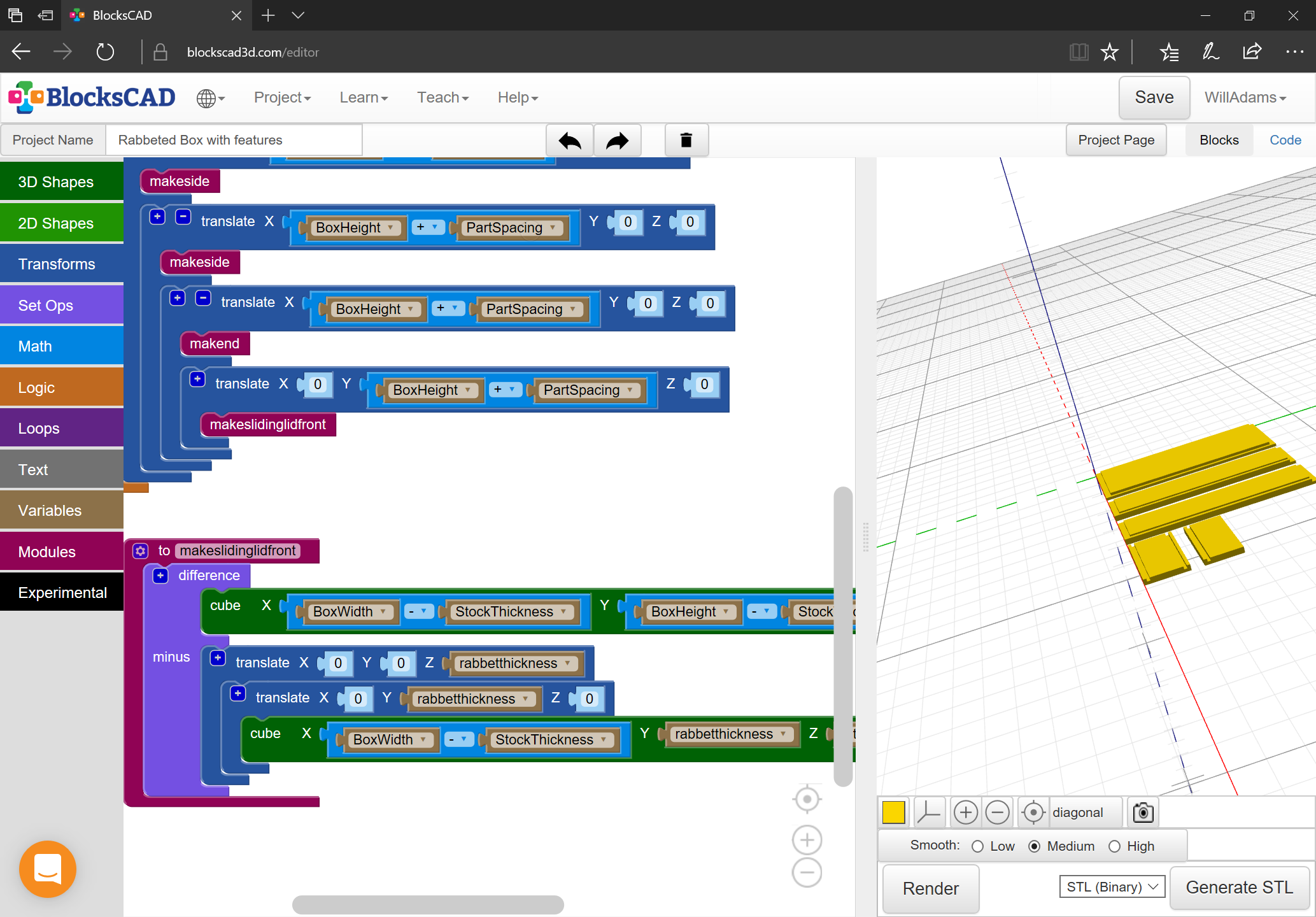
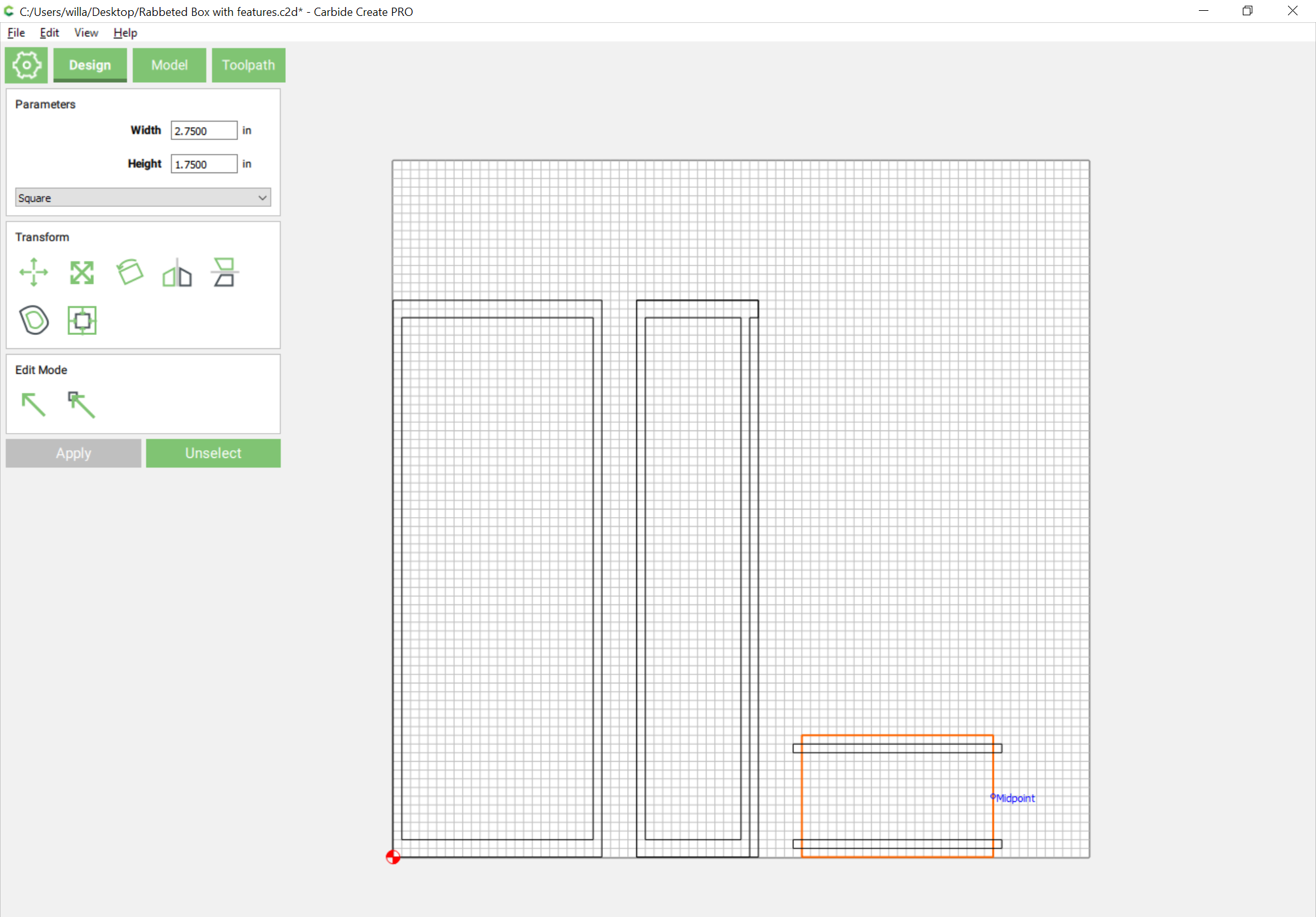
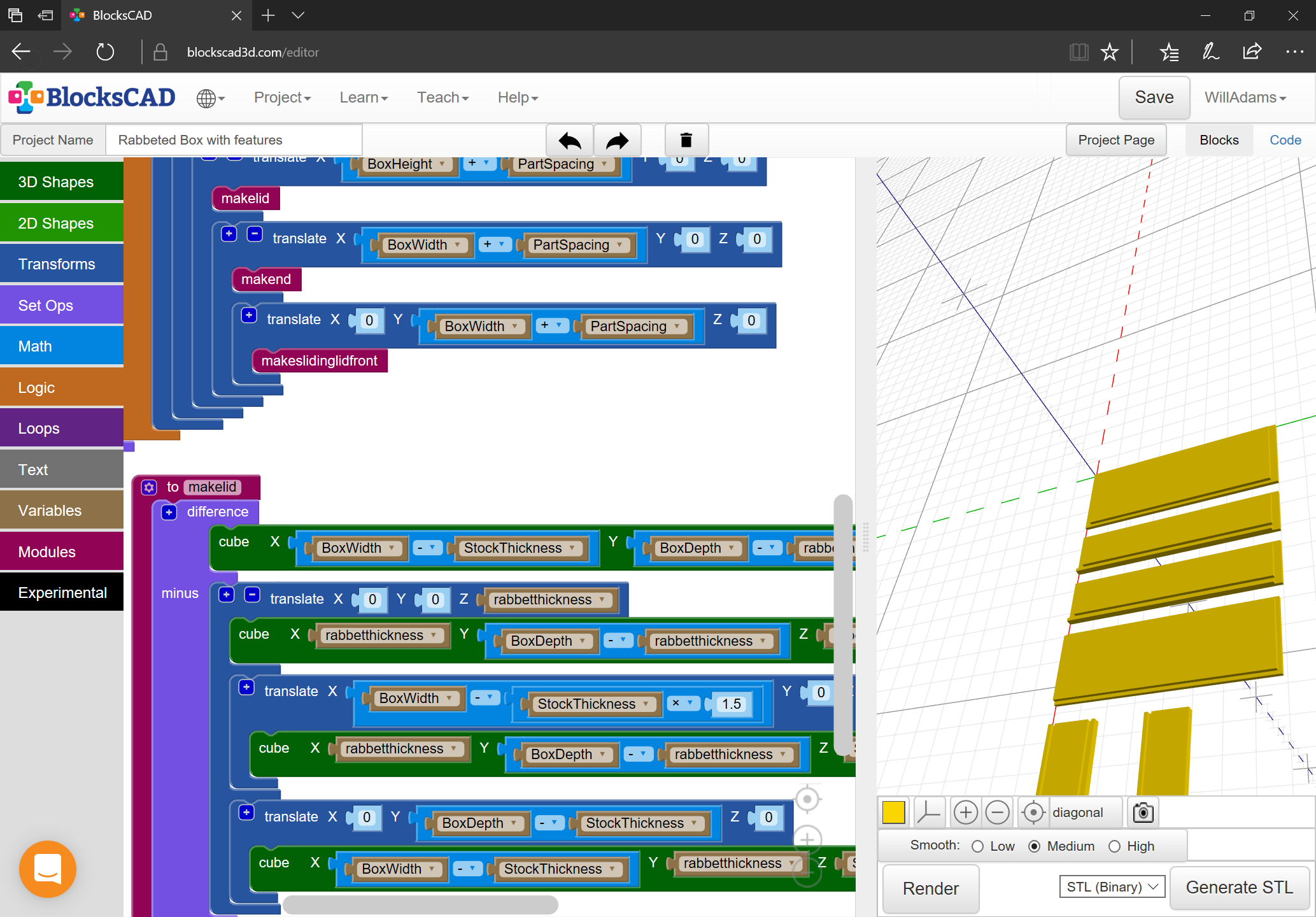
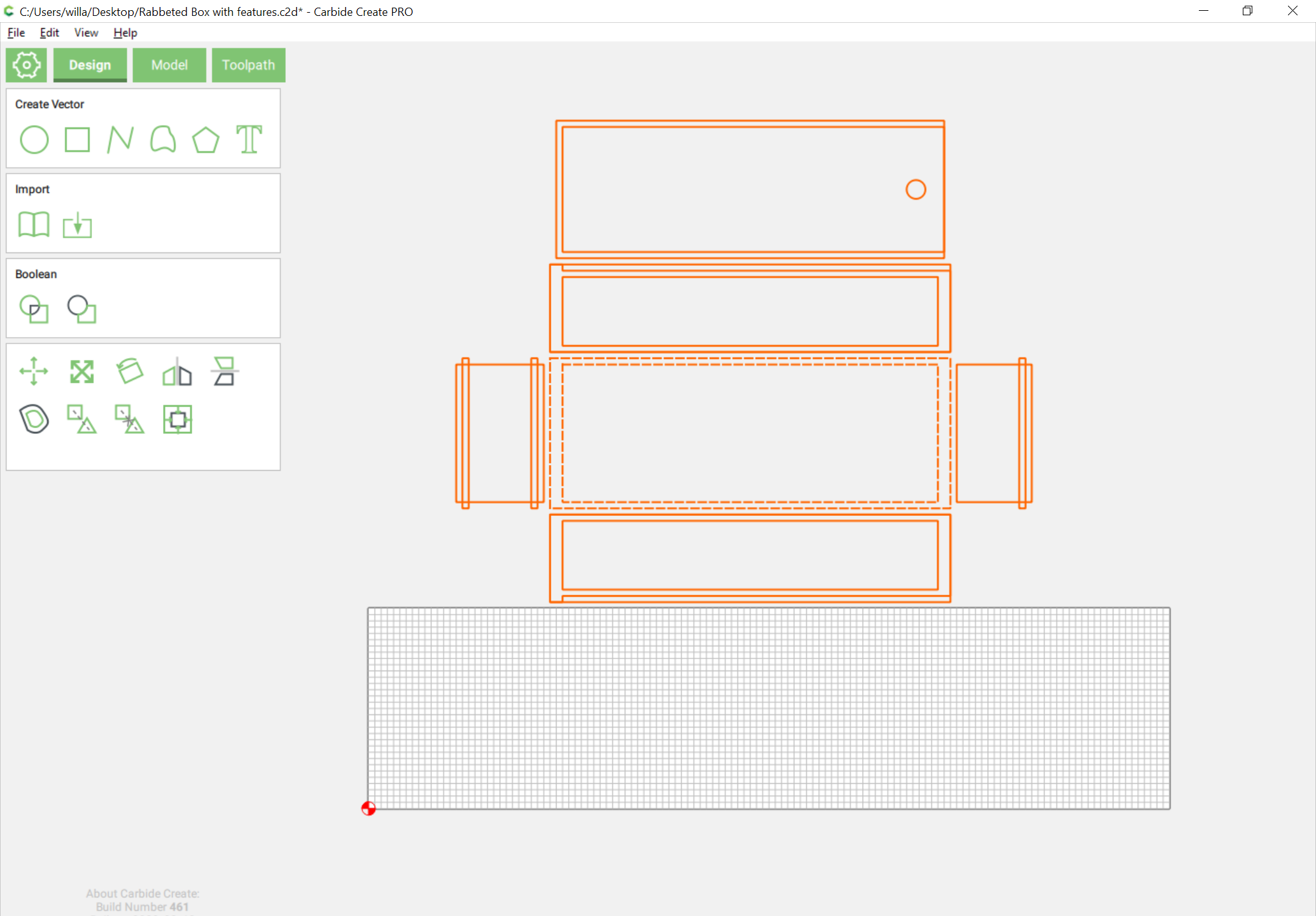
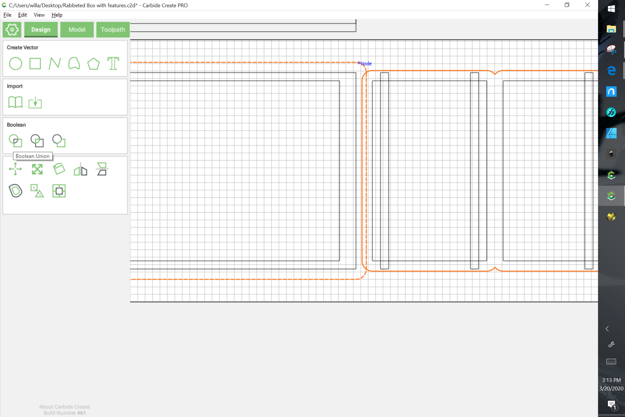
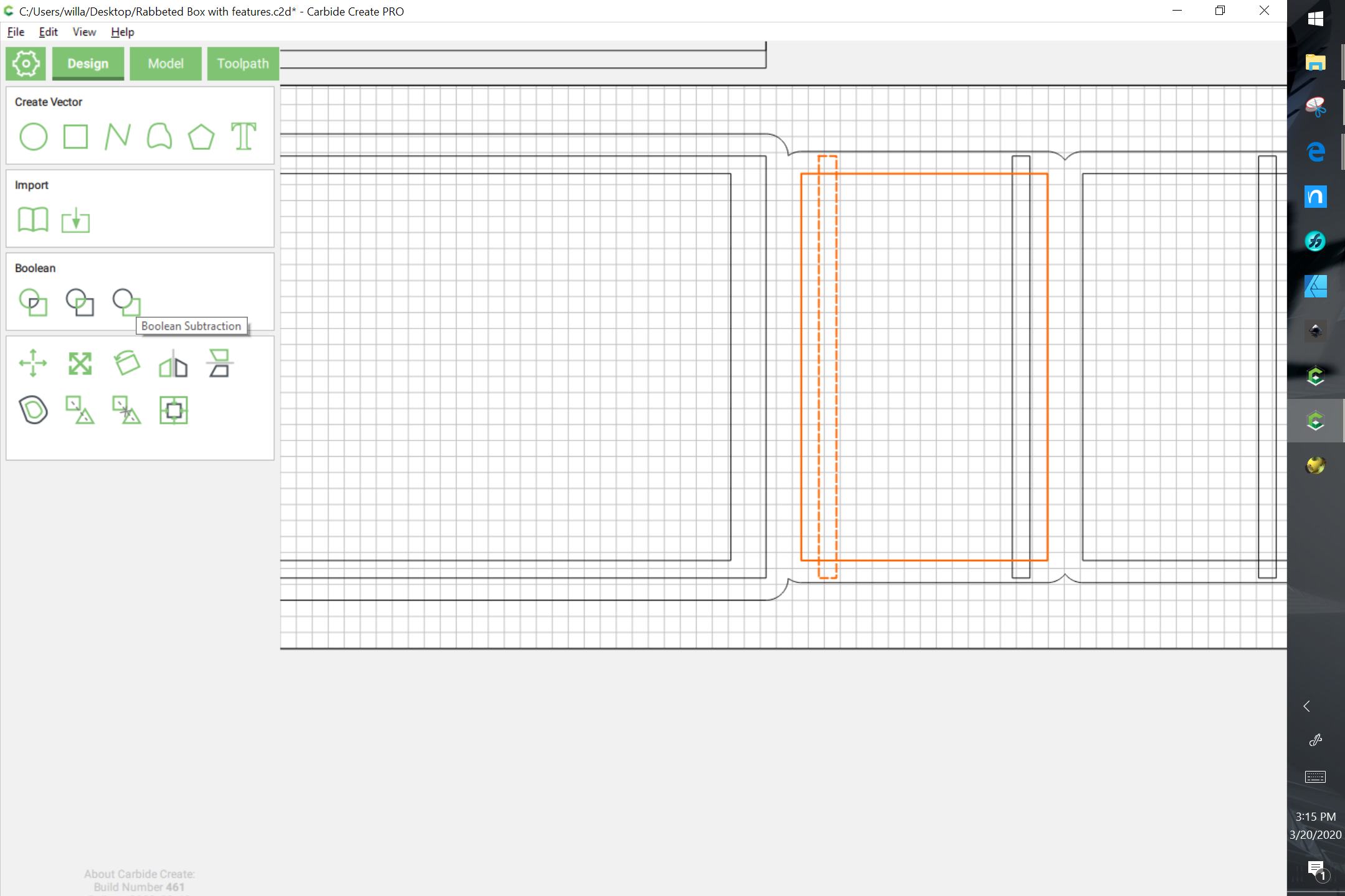
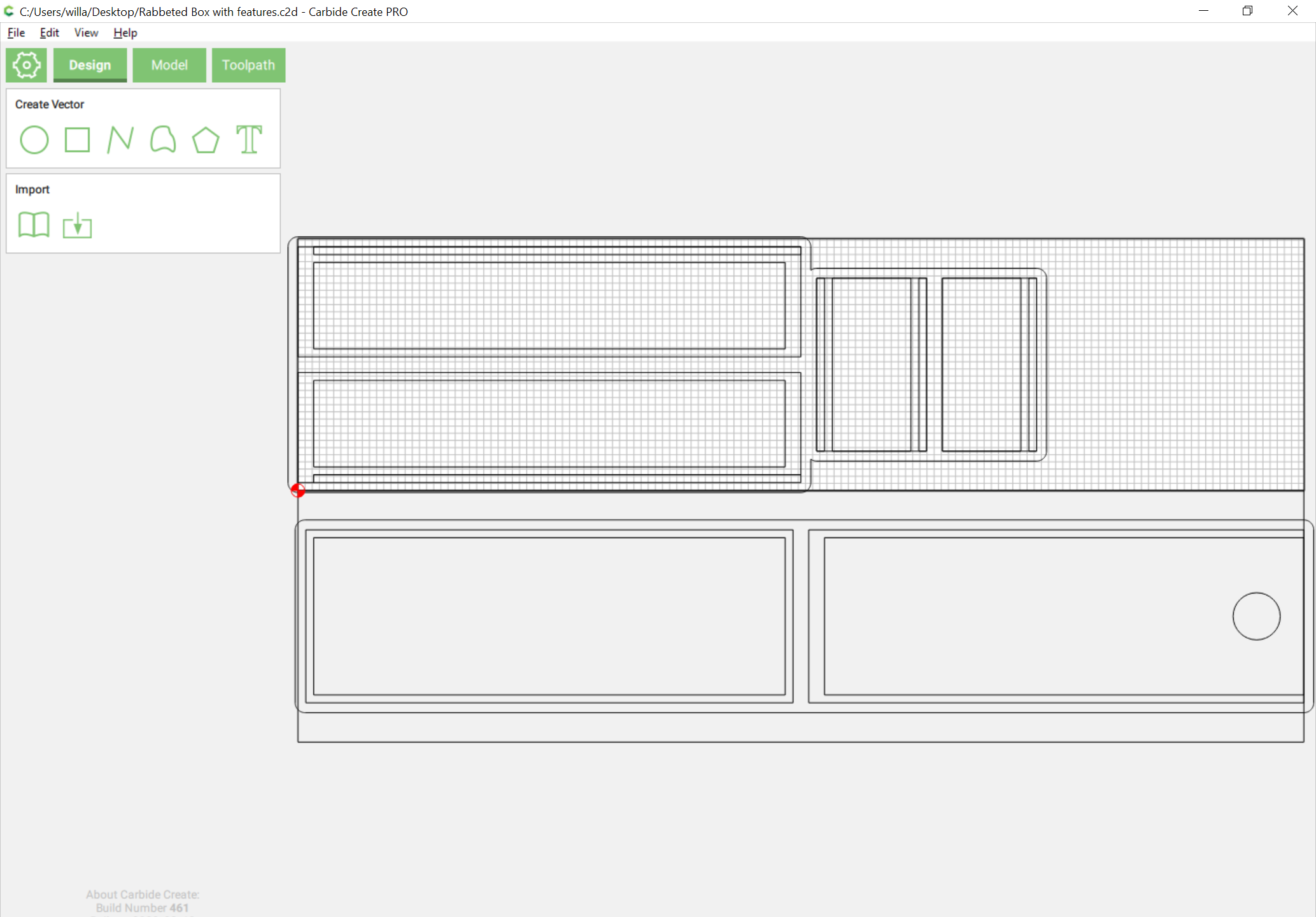
Drawing this up in Carbide Create is a matter of 3 rectangles: one the width of the height of the box, and the depth of it, a second stacked on top which has the width reduced by the rabbetthickness for the length of the rabbet, and a smaller inset one which is narrower by one and a half times the stockthickness, and shorter by twice that dimension as well.

Assign toolpaths for the rabbet:

and then the profile cut:

and this previews as:

Naturally it will be necessary to cut two sides.

It will be easier to manage things if the toolpaths are grouped.

1 Like

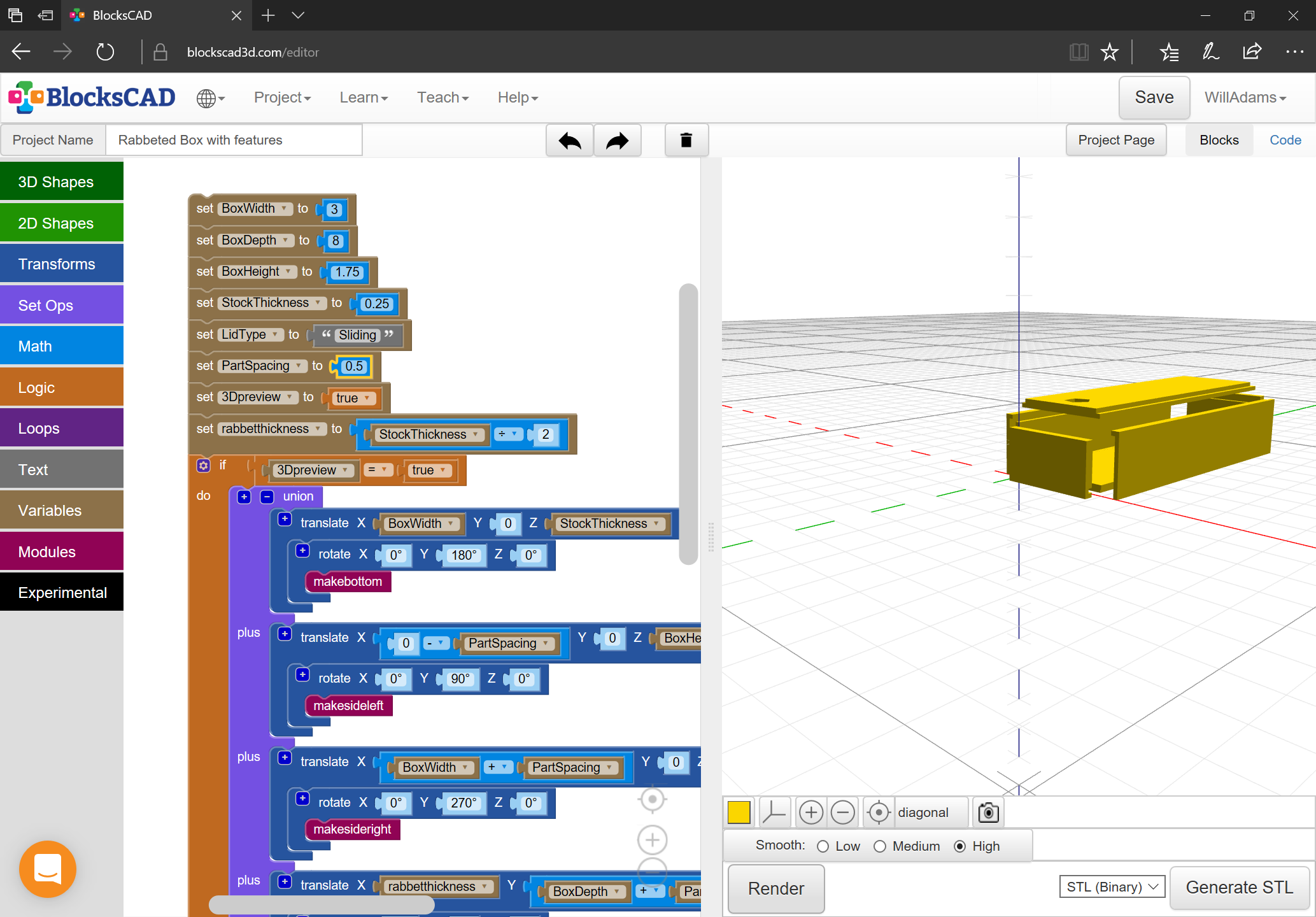
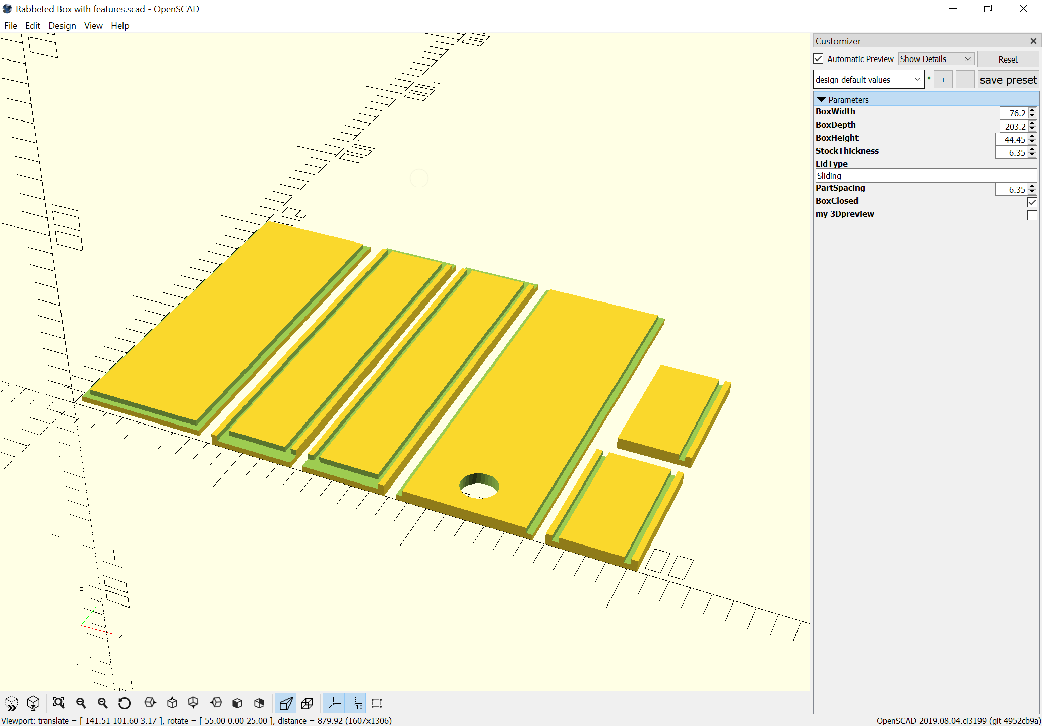
For the ends we need a cube which is BoxWidth less StockThickness wide, BoxHeight tall (for the back, and if there is a lid, BoxHeight less StockThickness tall and Stockthickness high with suitable rabbets:

These are easily drawn in Carbide Create, but at this point we will stop ignoring endmill radius, since doing so for this part would be egregious.

and:

with Toolpaths assigned as:

and

The front receives similar toolpaths, and the whole previews as:

Lastly there’s the lid which is much the same as the bottom, except that it is narrower than BoxWidth by Stockthickness, shorter than BoxDepth by rabbetwidth, and of Stockthickness with a rabbetwidth rabbet around the sides and at the back, and with a divot (or hole if desired) to facilitate opening.

Drawing the lid in Carbide Create is similar to the bottom, as are the toolpaths:

and

and everything previews as:

To do:

  • draw in geometry for finger hole (it needs to be a through hole unless one is going to cut the lid as a two-sided cut)
  • duplicate the side
  • arrange things so as to be able to check dimensions for fit
  • arrange things for efficient cutting from boards
  • modify/offset/add geometry to allow cutting rabbets completely w/o leaving darts/hyperbolic sectors at the corners*

Next we check fit by suitable arrangements.

Increase size of working area, group each set of parts together, then drag around to check:

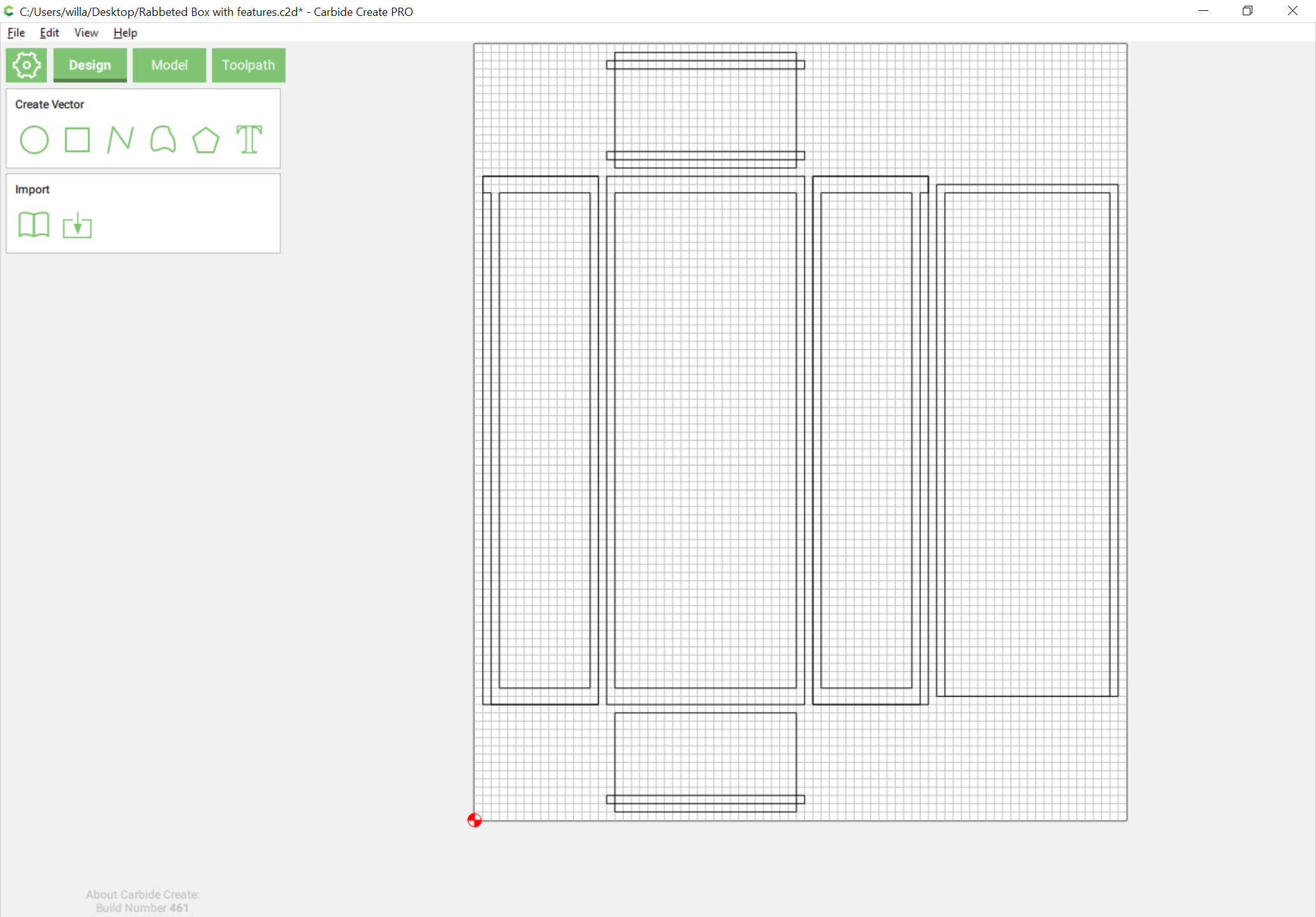
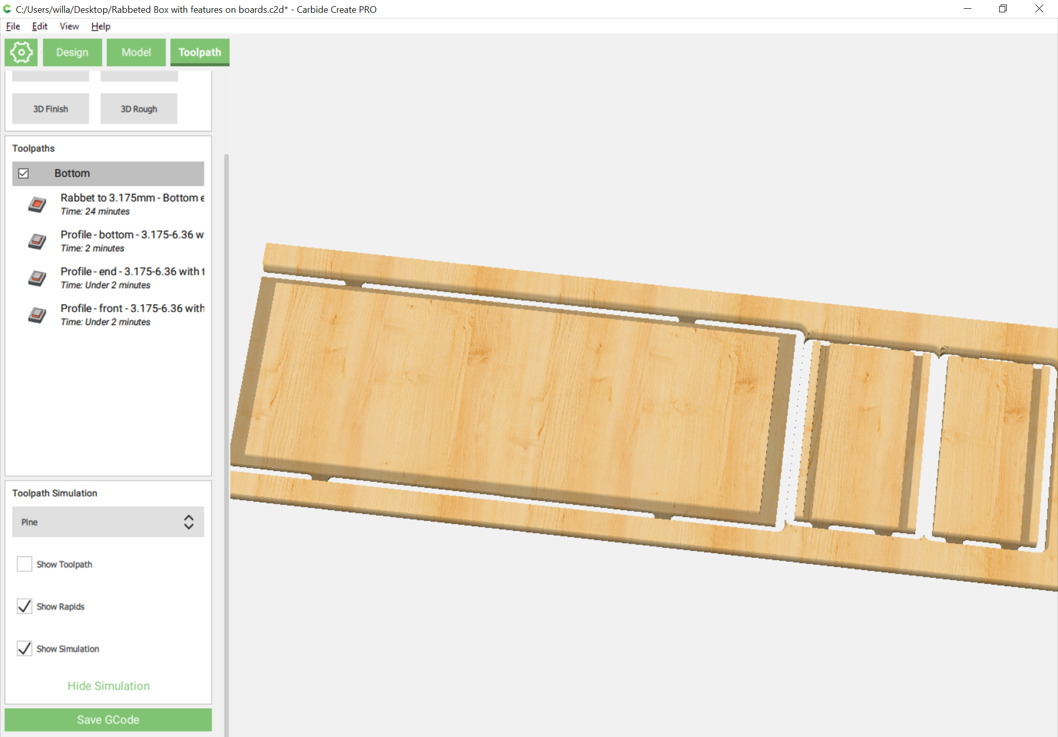
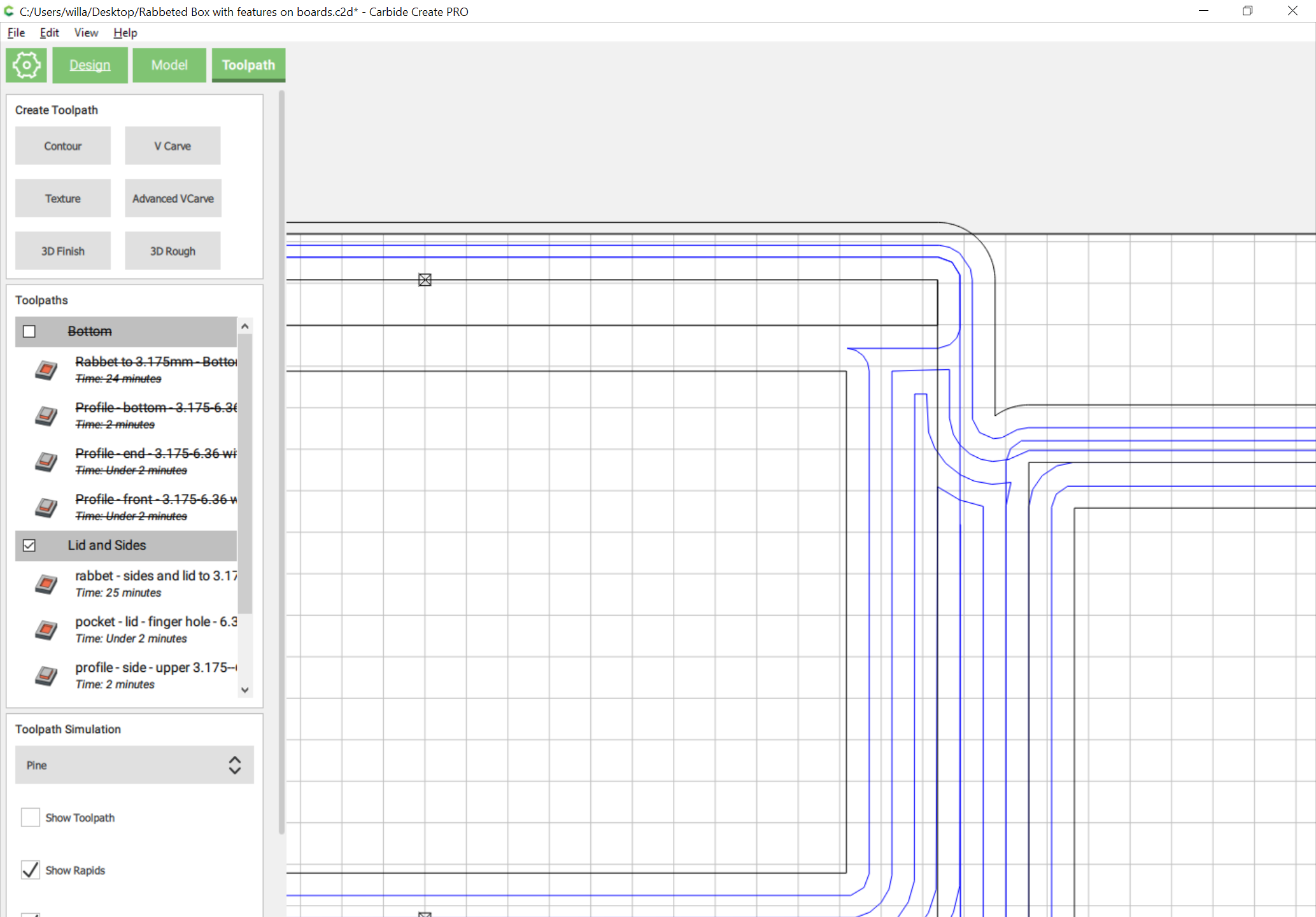
Next, modify/add geometry and arrange for cutting out of some reasonable size of stock which will fit on a machine. The largest part is 3" x 8" so we will try 4" wide boards which are a bit longer than 16" long (which will allow this to comfortably fit on any Shapeoko (my apologies to the Nomad folks).

Before we get too far, let’s mark the lid with a finger cutout:

Then we select everything and rotate it 90 degrees:

We’re going to need two boards, so let’s draw those in:

(note that you’ll need to use boards a bit longer than 16" at least for the sides/top, the bottom board can be ~12" long)

Next we arrange the parts within those two rectangles leaving room for an endmill to get into things:

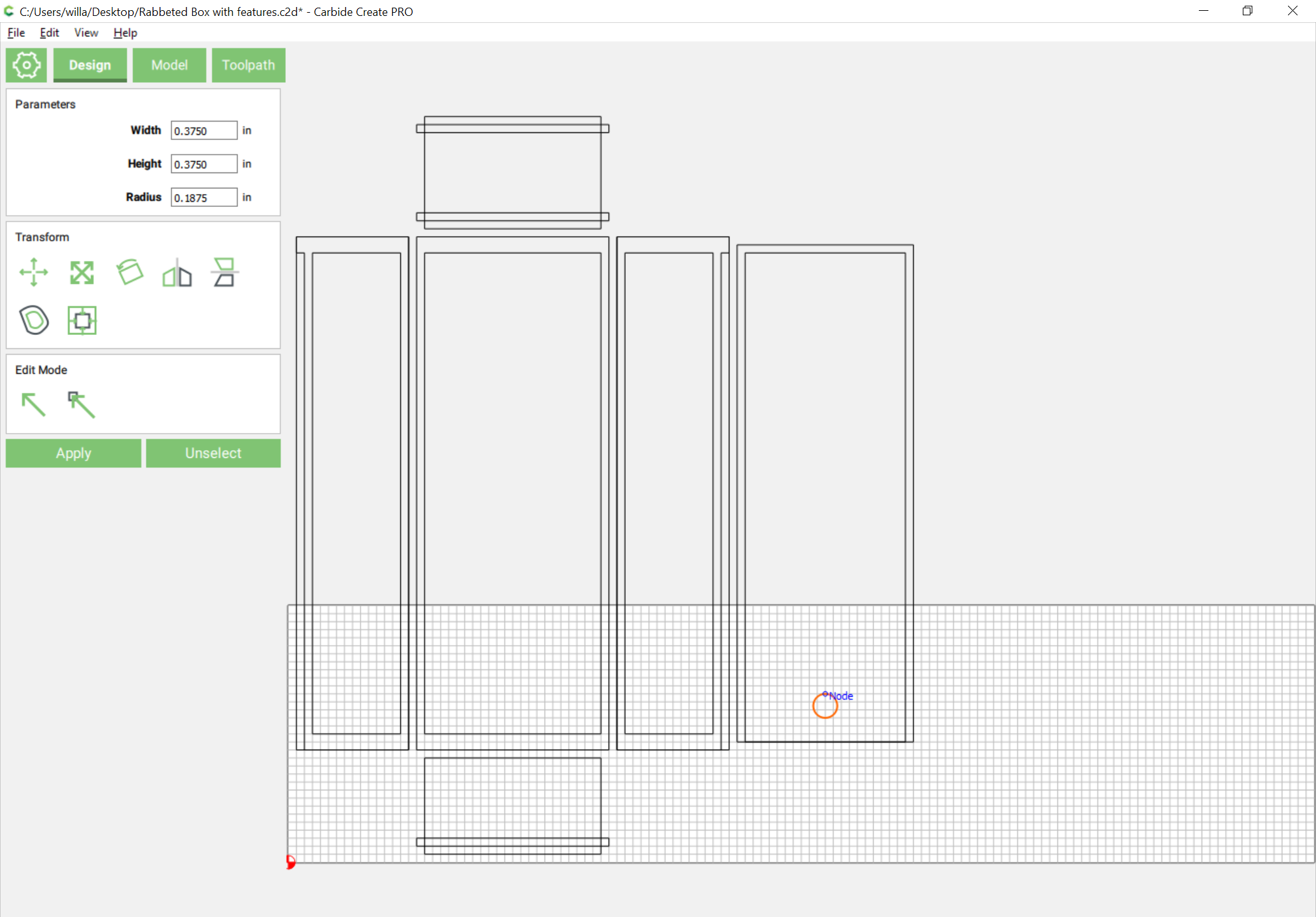
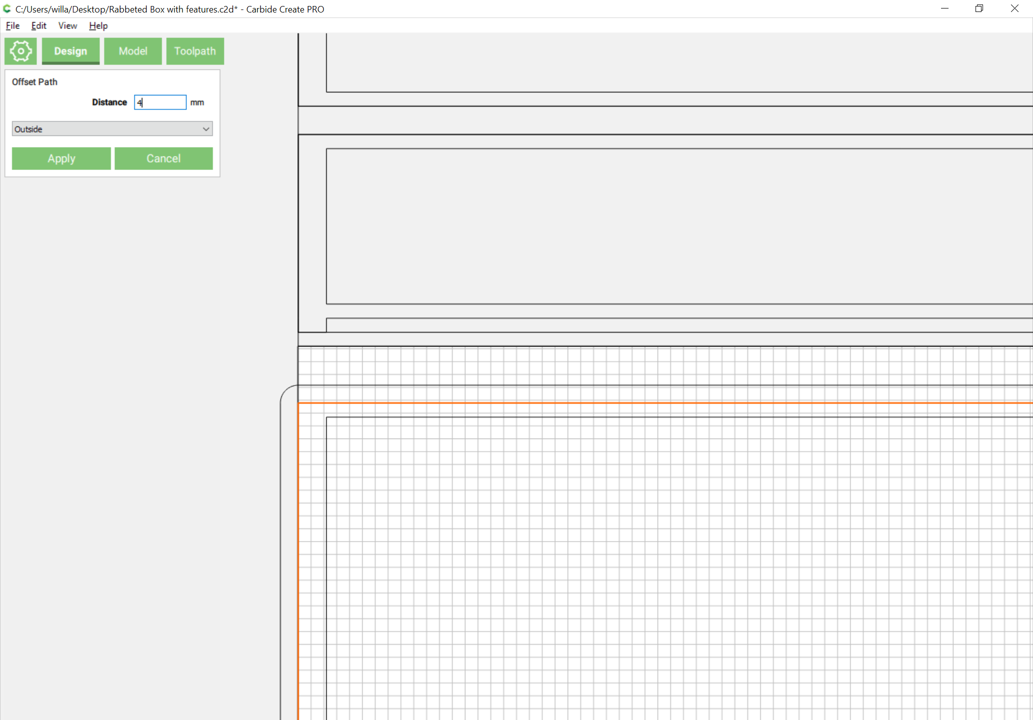
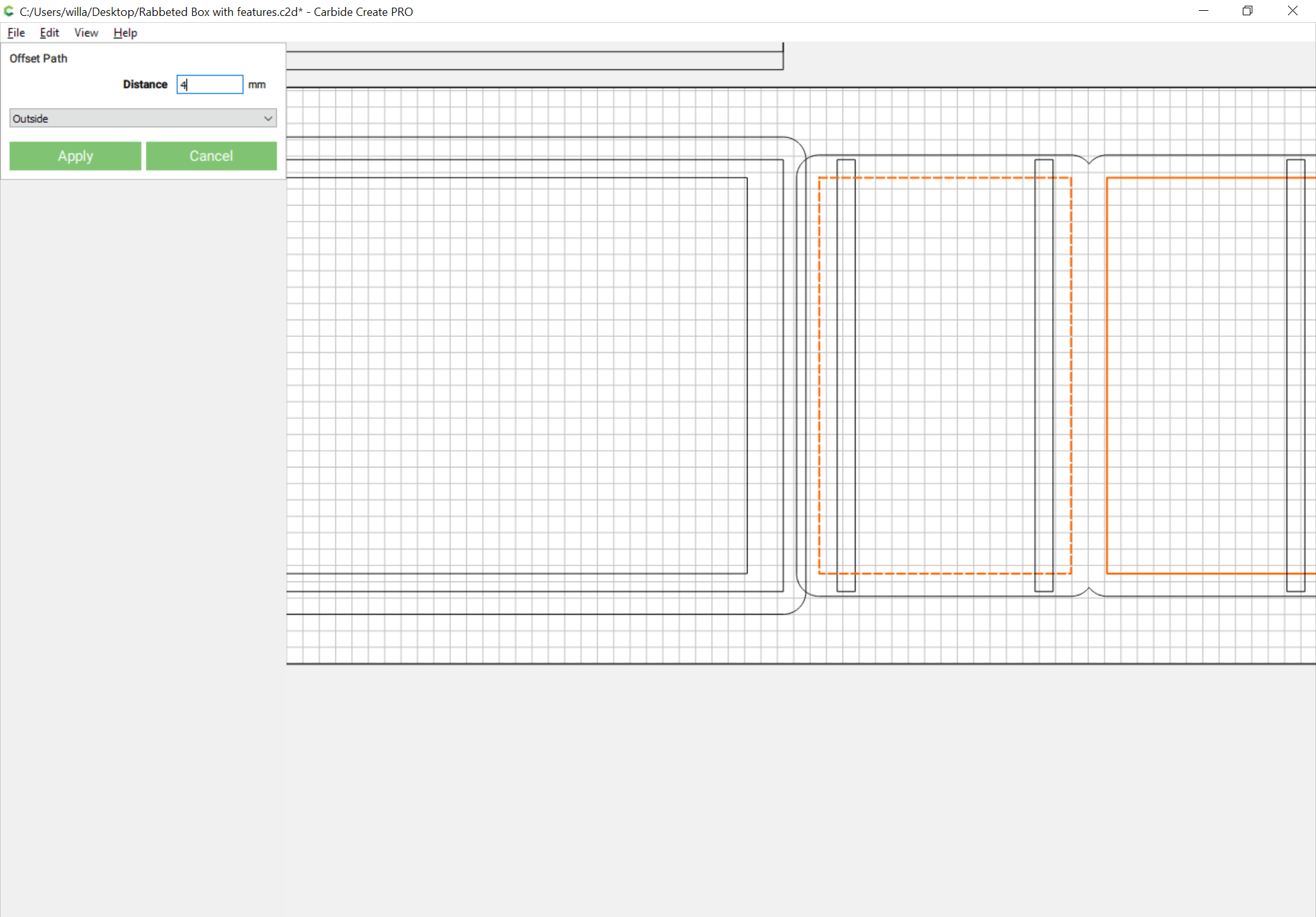
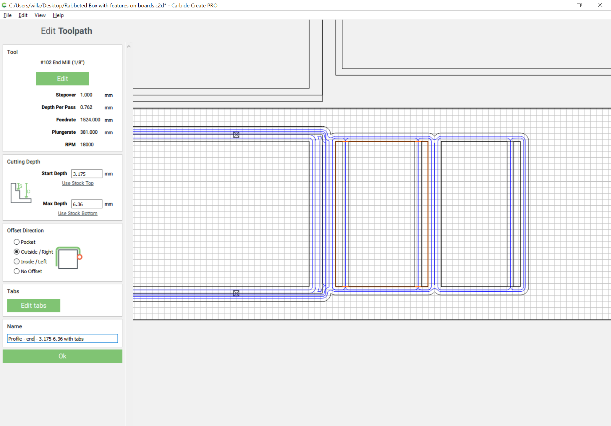
and expand/modify geometry as necessary to allow cutting things out and to use a 1/8" endmill (the grooves for the top/bottom will be slightly increased in size to allow it to fit)

Delete all of the earlier Toolpaths as we’ll be recreating them.

Switch to metric and zoom in and select the perimeters and offset them by 4mm:

and

Select the outer paths and Boolean union them together:

Where you want cuts down to rabbetwidth select the geometry and Boolean Subtract:

Then select the geometry you want full thickness and the unioned outer profile and apply a pocket:

Then select each part in turn and assign an outer profile cut and add tabs:

until one has toolpaths which preview as:

Select everything and shift down 4":

then disable the Bottom toolpath group and make a new one for Lid and Sides:

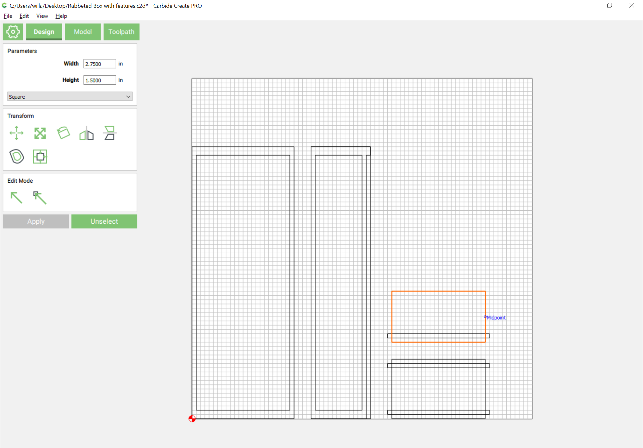
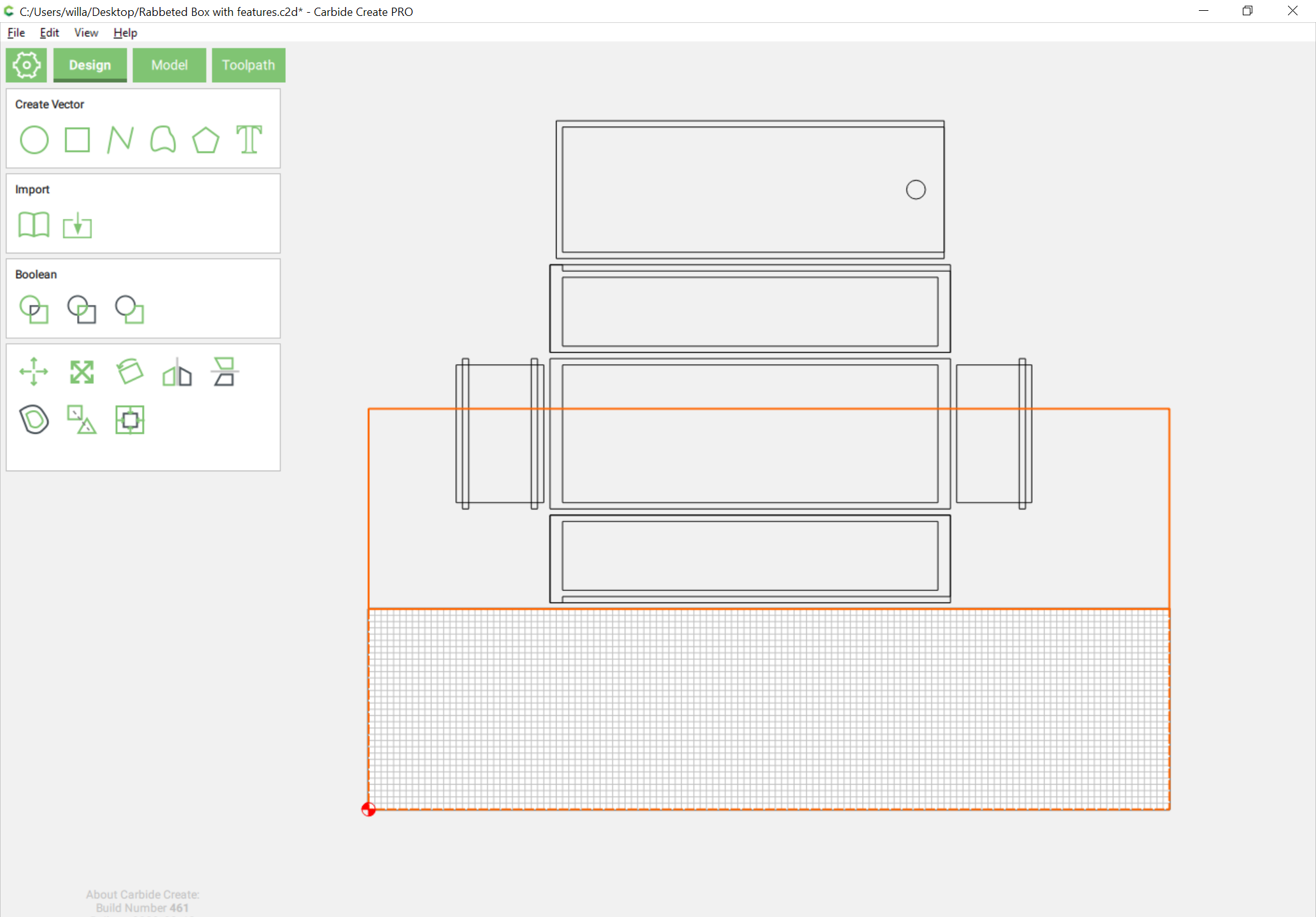
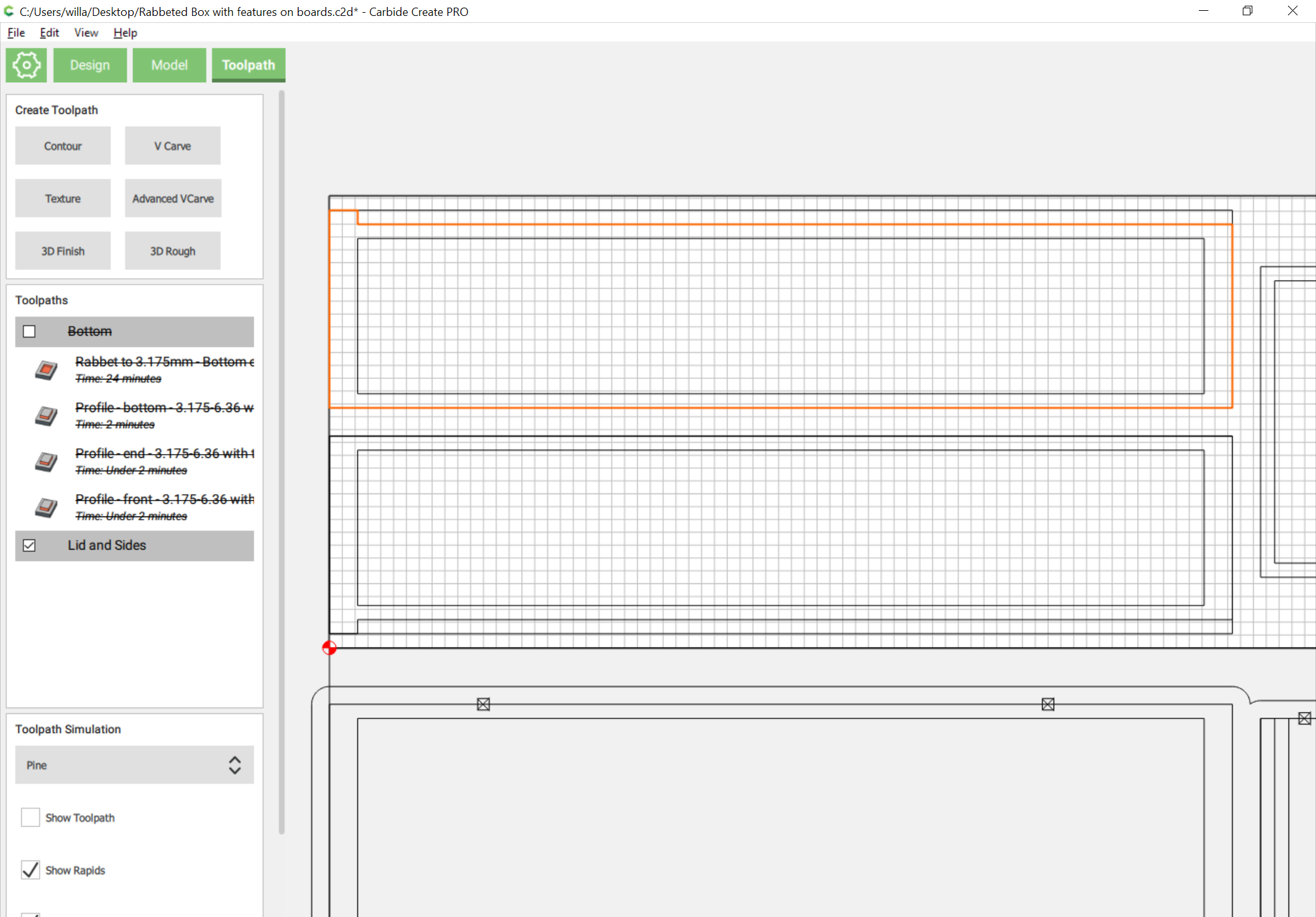
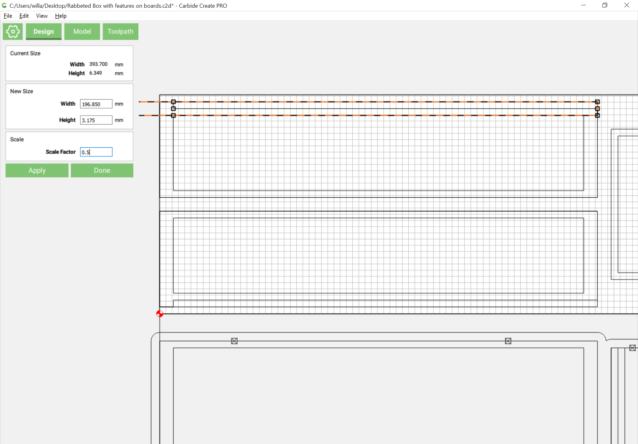
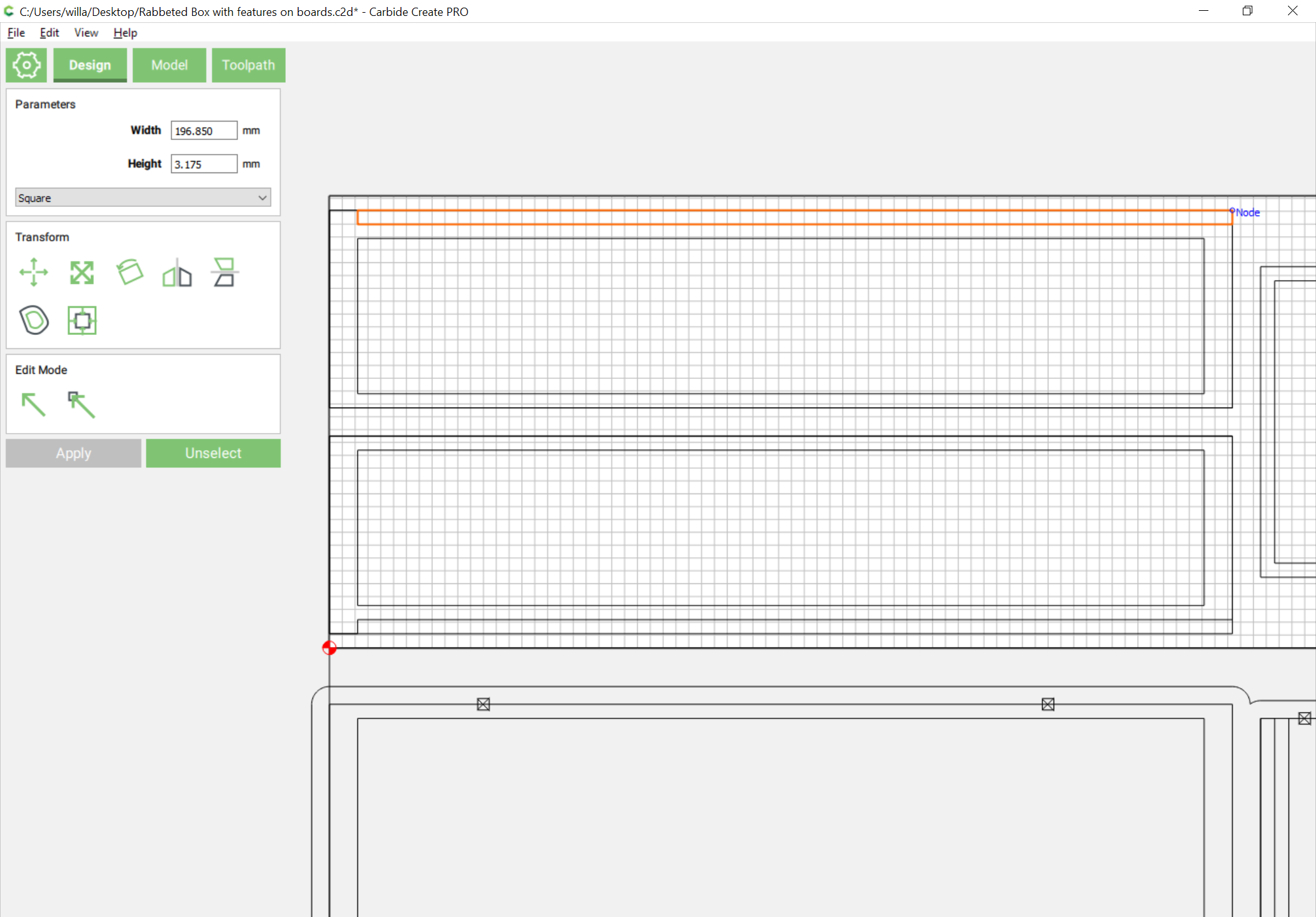
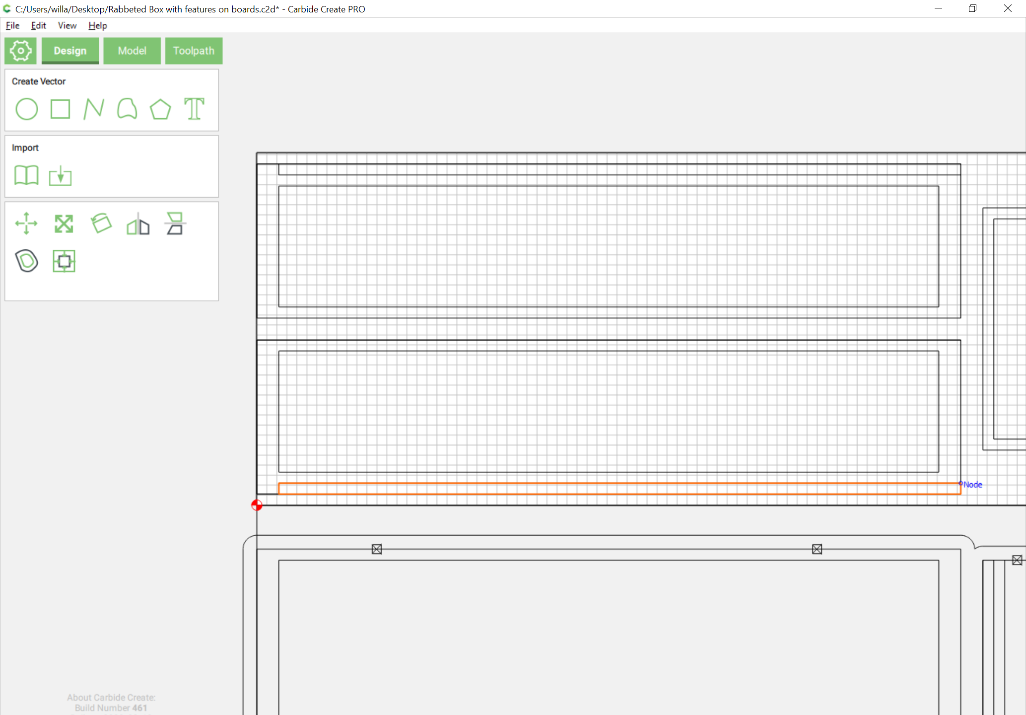
then it’s necessary to go back to the Design pane and draw up a rectangle for the stock which we wish to leave — note that since CC draws center–corner it’s easiest to draw at twice the size necessary, then reduce to 50%:

Duplicate and drag the dupe to the other side:

Then repeat the outlining of the profiles, unioning, and assigning of toolpaths:

Note that if the program doesn’t cut where needed:

a slight adjustment may be necessary:

One can selectively enable/disable the groups, and generate G-Code to cut the parts:

And it seems I messed up the sides.

I believe the fix is to add another pair of grooves to the sides.

Hopefully this is right:

The Z is cut from the underside, so needs to be rotated and shifted into place:

(it would seem the bottom was a bit larger than it ought to have been — will need to adjust that)

Once things are oriented (and adjusted) the box fits together:

and explodes:

And finally, it’s possible to open the box:

Transferring into OpenSCAD was straight-forward:

Next is exporting DXFs

Attached. Rabbeted Box with features.dxf (3.9 KB) — it will be necessary to work out getting the rabbets out of the OpenSCAD file as well.

The only part whose size was wrong was the bottom, so:

assign toolpaths and we get:

1 Like

Okay, went to Home Depot and bought half-a-dozen 1/4" x 4" x 4’ “craft” boards (which are actually 1/4" x 3.5" x 4’):

(and yes, I went through all of the over 200 boards which were in stock at my local store to find the 6 which were decently straight and left the stacks neater than they were when I arrived)

It should be feasible to change the job setup so that we clamp up three boards on effectively 10.5" wide stock and cut one box all at one go, but that’s a bit more waste stock than I can accept, so we will shorten the box a bit — the top/bottom are fine, we just have to shift the top/bottom a bit.

1 Like

1½″ should fit, and it also raises a point on the tab location — probably better at the sides of the front/back of the box.

This file is just for .25 inch wood right. Also how do you separate such as the lid and base into separate pieces because the 16x7 file does not fit on the Shapeoko 3 which I have and not the xl?

Should fit on an SO3 — if it won’t, just rotate a 3.5" x 16" rectangle, mill it as a pocket and secure one board in that pocket as a fixture:

Attached. Rabbeted Box with features 3×8×1½″.c2d (182.1 KB)

To separate, just drag the 3.5" x 16" boxes around and disable the toolpath group you don’t need: