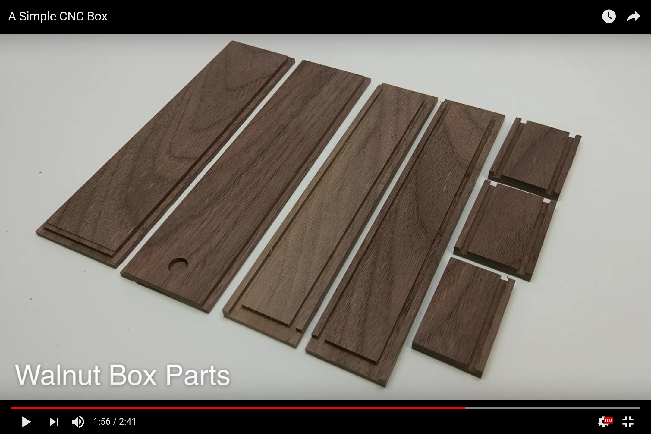
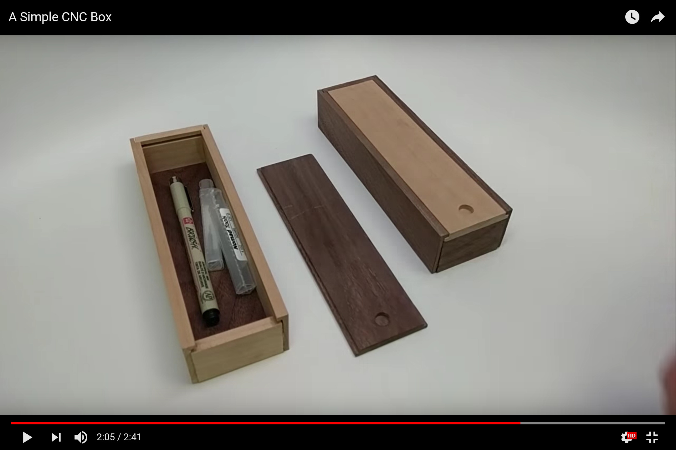
which unfortunately, doesn’t go into depth about the CAD/CAM aspects of this. Since it’s so simple, it’s an excellent project to show one technique for drawing it up. Also on the wiki at:
Thickness(s): 5 thick wood. 0.0625" thick plexiglass and 0.125" plywood
Inset: 0.125" from front and back edges and .25 deep
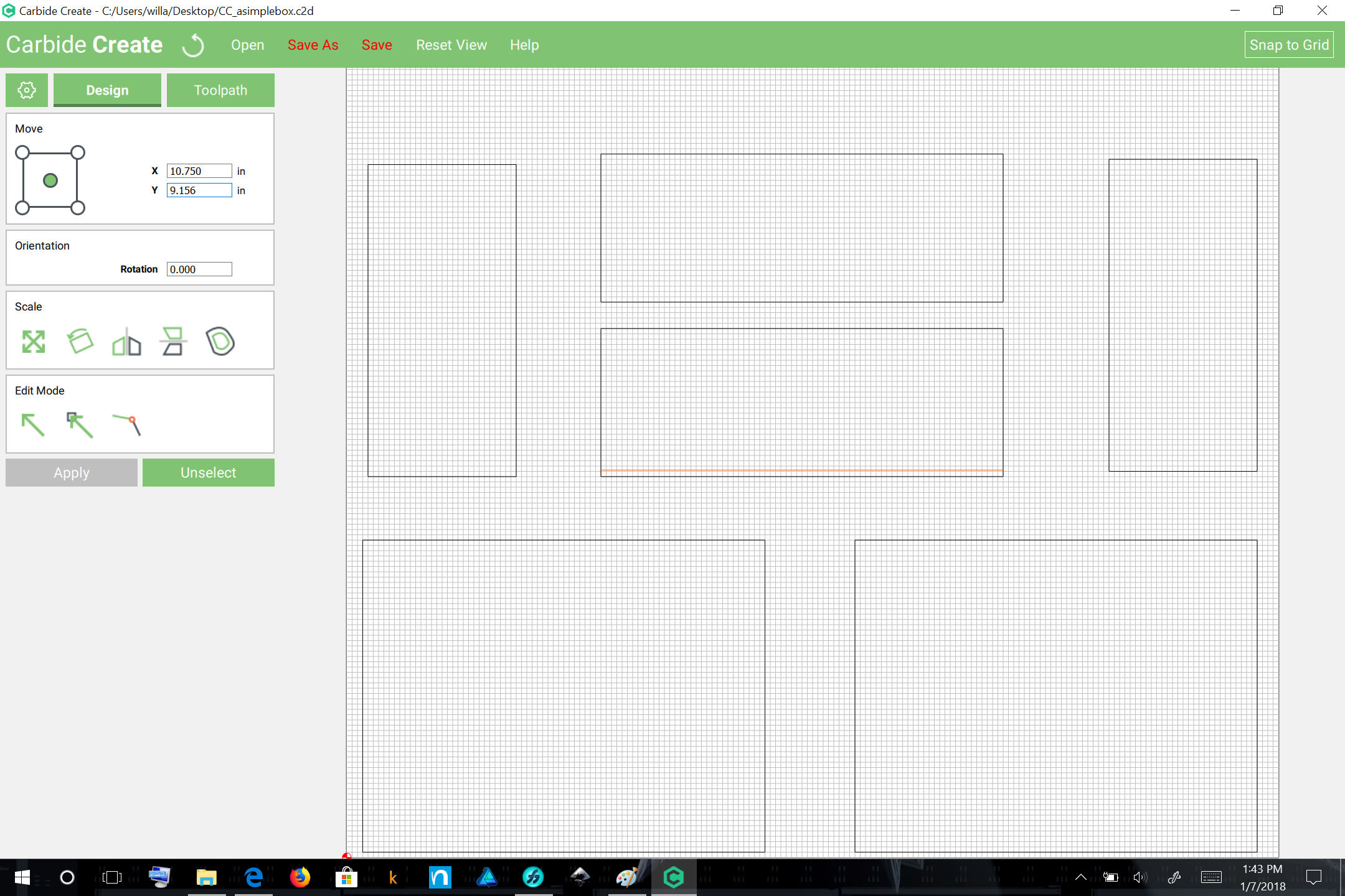
It is also necessary to determine the orientation of the box — this particular case is envisioned as standing up, or hanging on a wall, more as a shadow box.
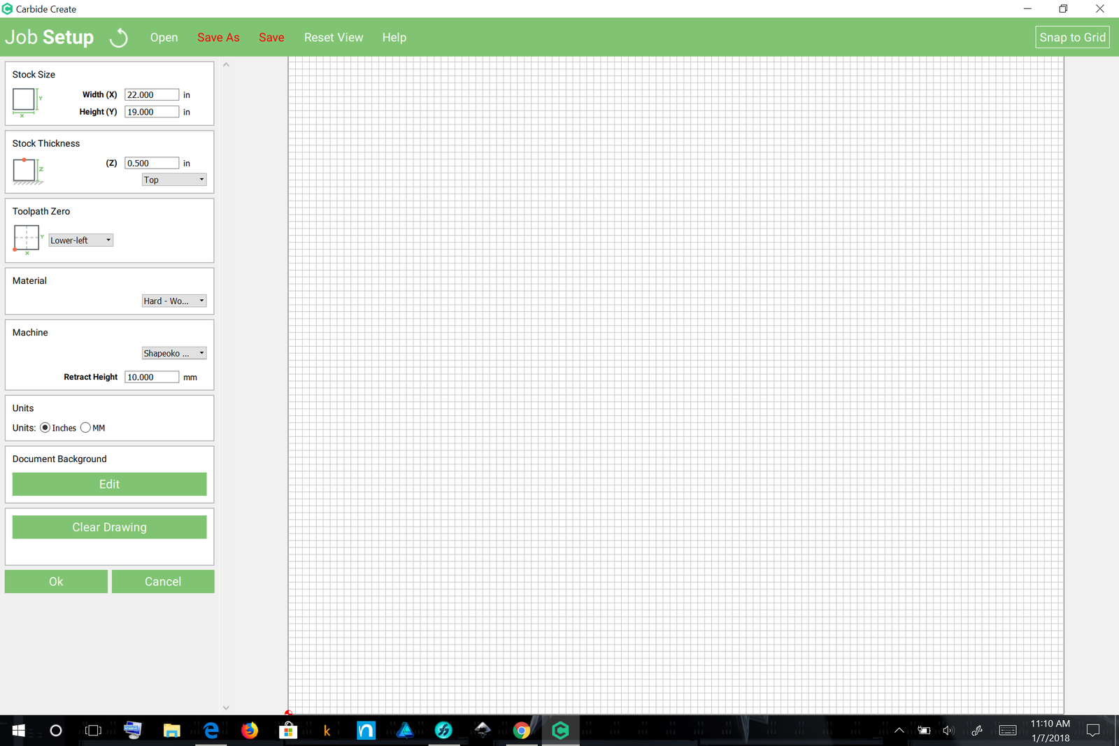
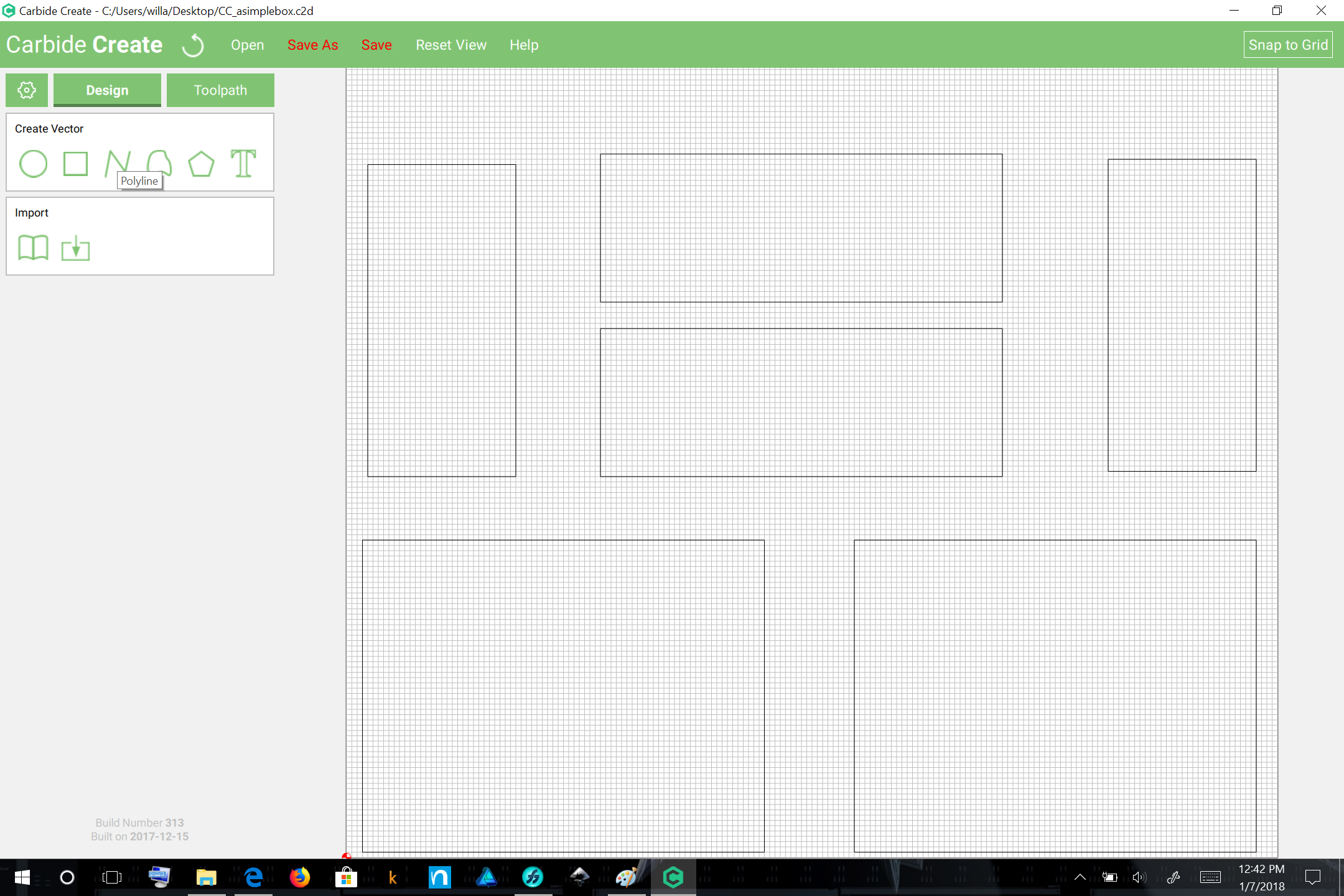
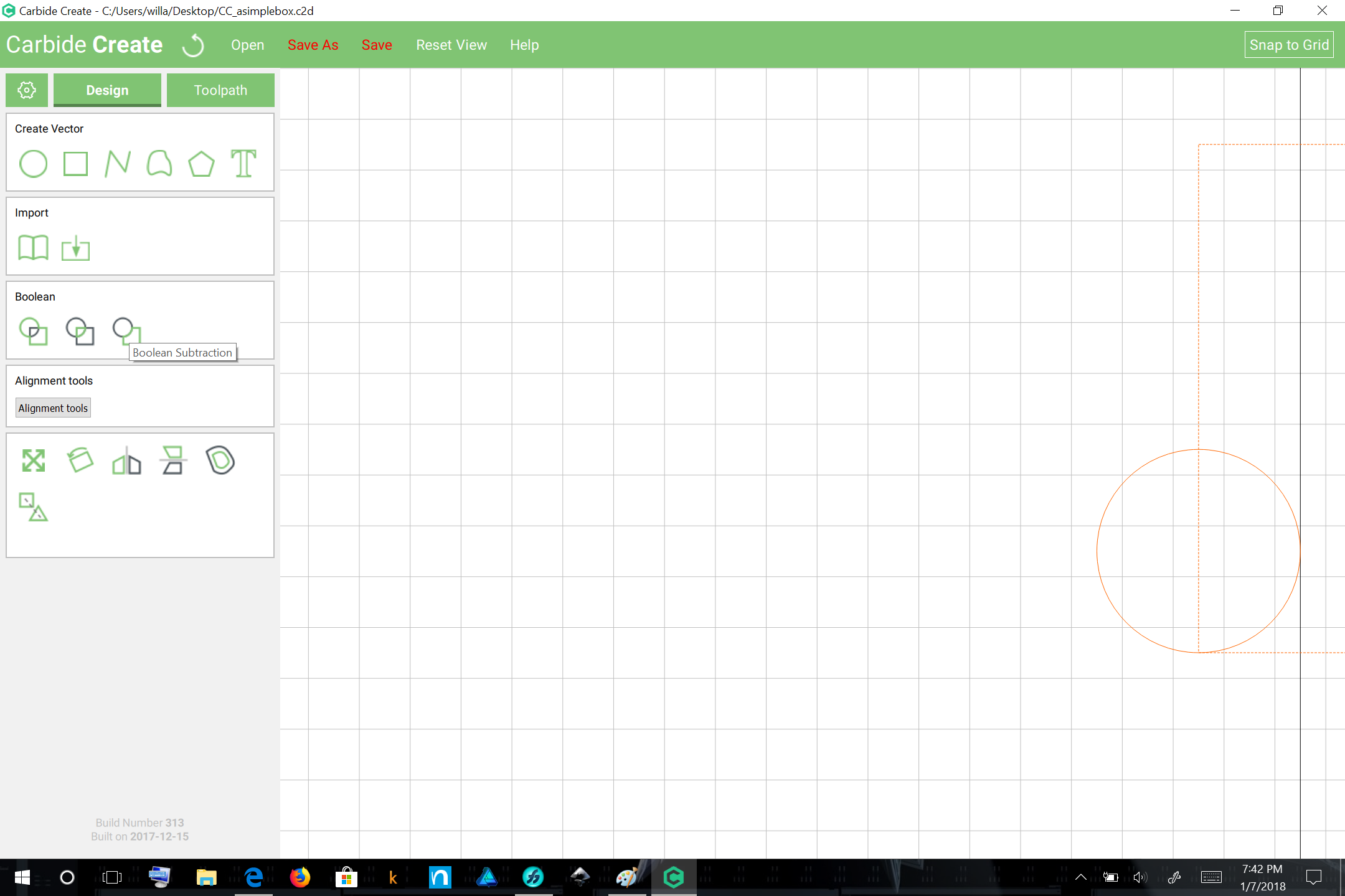
Launch Carbide Create and choose a stock size with reasonable proportions for your monitor and which is comfortably larger than all the parts involved:
It is probably also helpful to go into ‘’‘Document Background | Edit’‘’ and set the grid spacing to and integral value of the box dimensions — 0.125" should be fine enough:
The shadow box which we envision making will have the orientation of the boxes from the video being set on their left side as viewed above. Therefore:
the left side will be full depth so as to function as a stop
the right side will have its depth reduced to allow the front of the box to slide in place
the top and bottom will have dadoes for the front and back, and rabbets (rebates) for the side (please see the glossary if unfamiliar with any of these woodworking terms: https://www.shapeoko.com/wiki/index.php/Glossary )
the front and back will need to be reduced in dimension to fit — we will not be routing rabbets in them due to the thinness of the selected stock
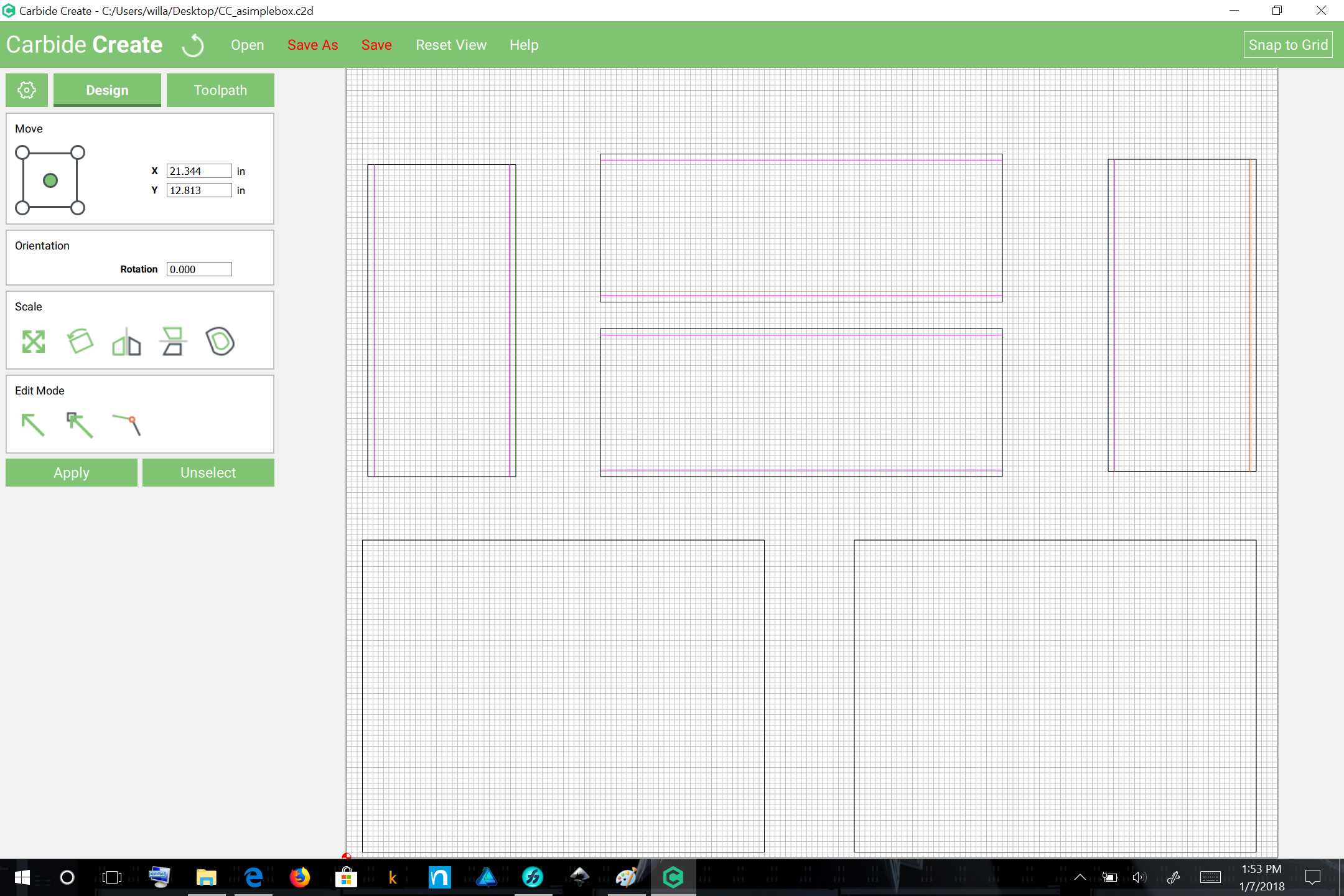
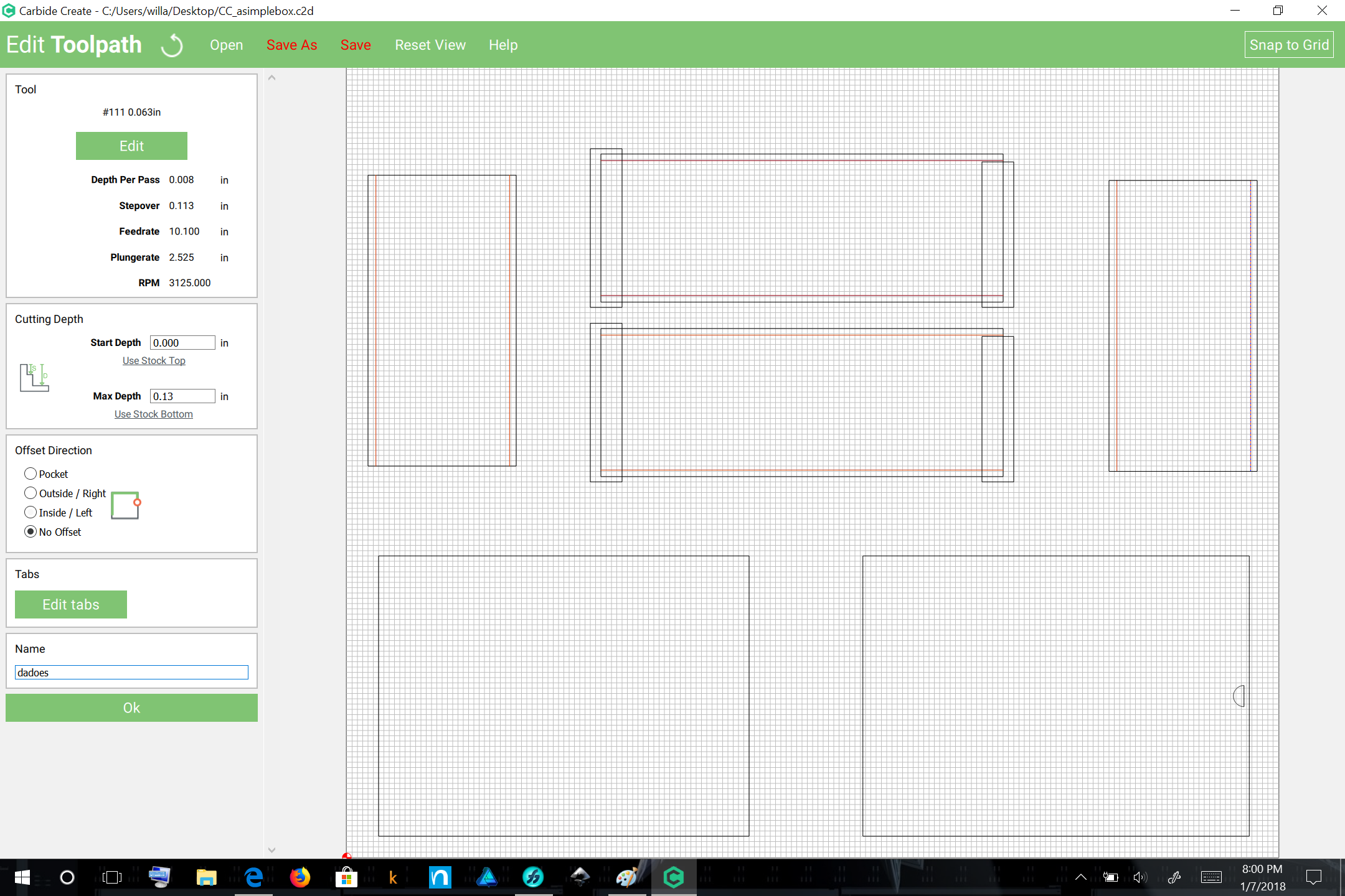
Begin by drawing in and positioning the dadoes for the front and back in the top, bottom, and sides — these will be cut with an 0.0625″ endmill and if done as pockets would need to be at least 10% wider — rounding up to 0.07″ would be one option, but is problematic in terms of positioning. An alternative is to draw in a line and cut as a follow path operation, trusting that the endmill will cut a bit wider than its nominal dimension due to runout and expecting the sheet good to probably be slightly undersize. For simplicity’s sake, we will do the latter.
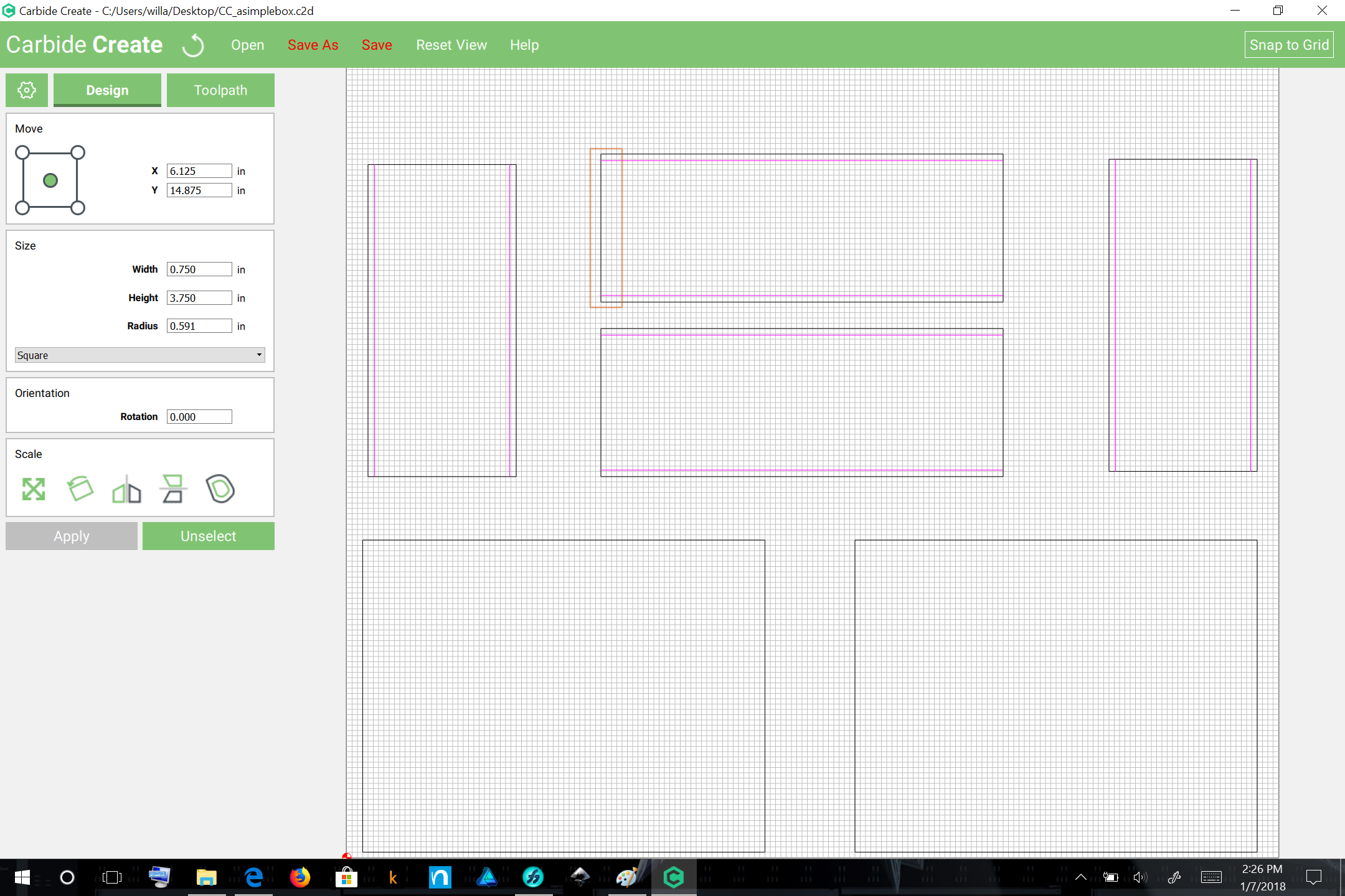
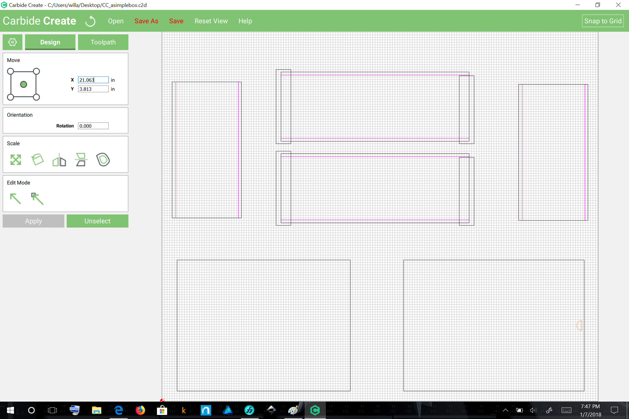
Use the Polyline tool to draw in a line beginning and ending at the corners of each edge which you need a dado along:
Note that you will need to roundup or down (used 0.063″) and the line should be positioned at
0.125″ (inset) + (0.0625″ (dado thickness)/2)
so
0.125″ + 0.03125″ ~= 0.156″
Repeat this process for each dado (note that you may need to deselect and reselect to get in and out of the various modes, esp. if you choose to duplicate geometry):
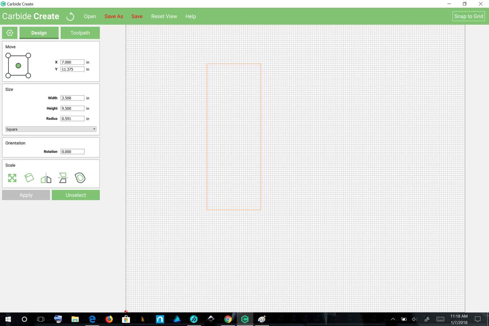
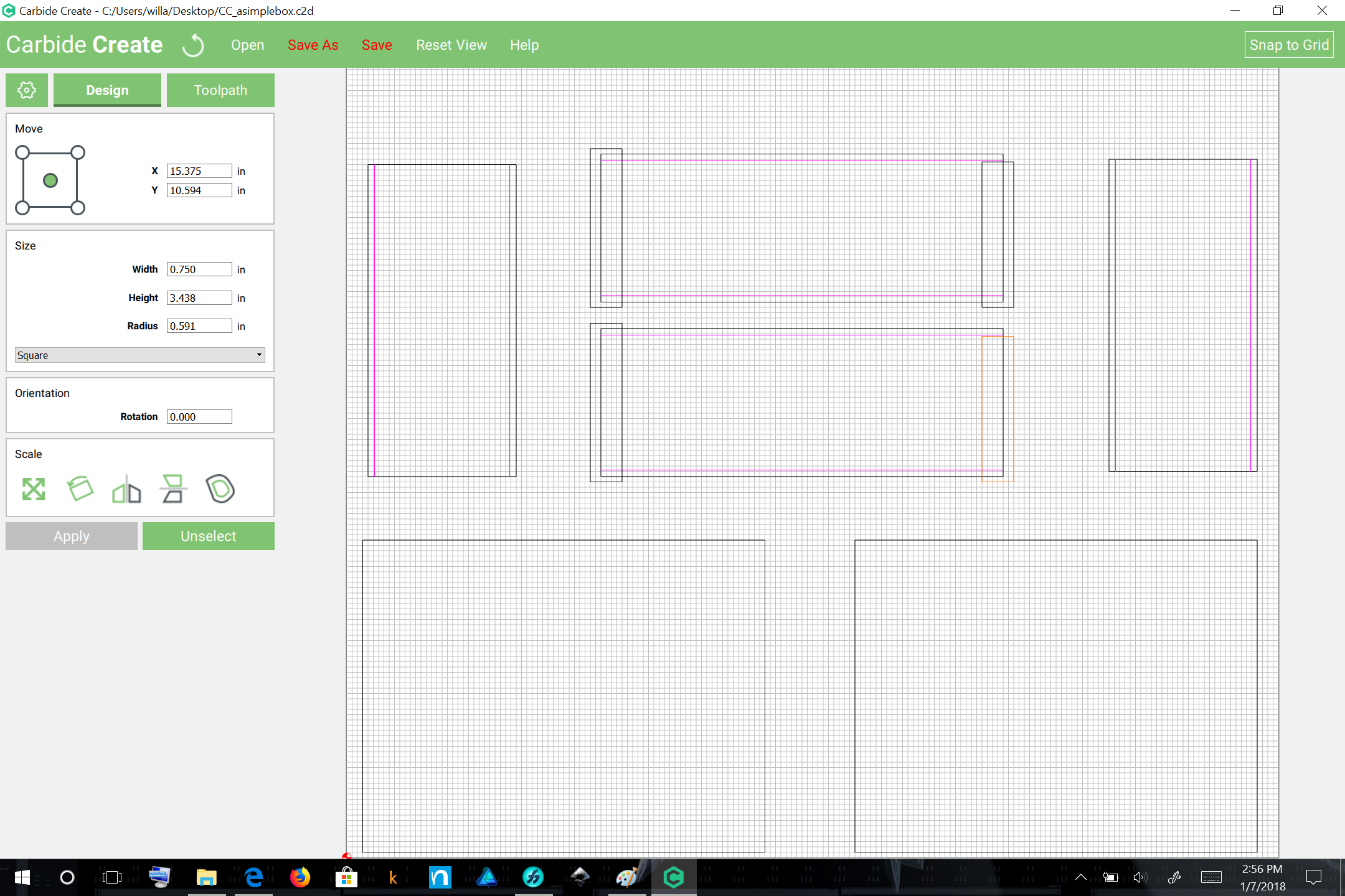
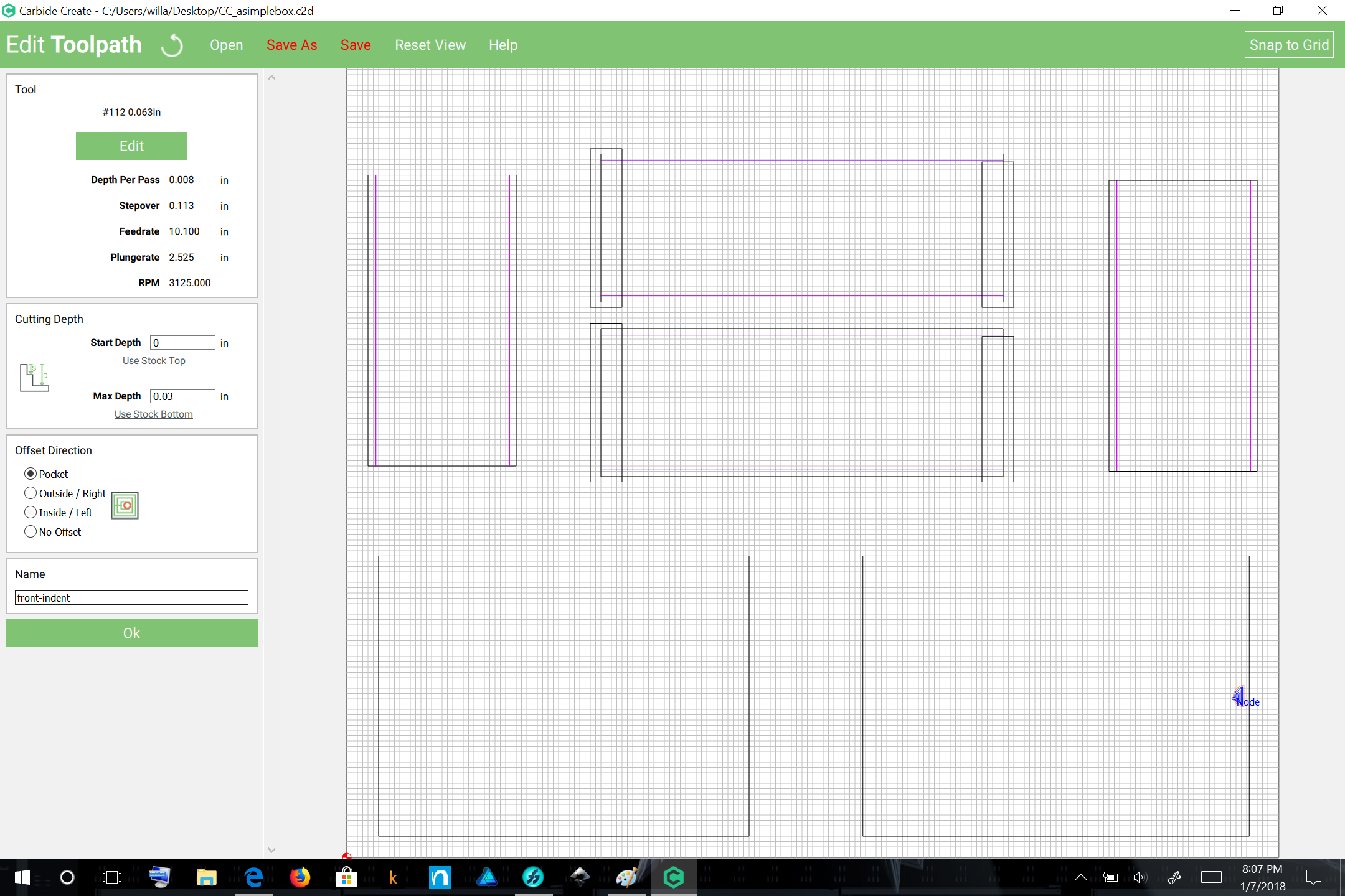
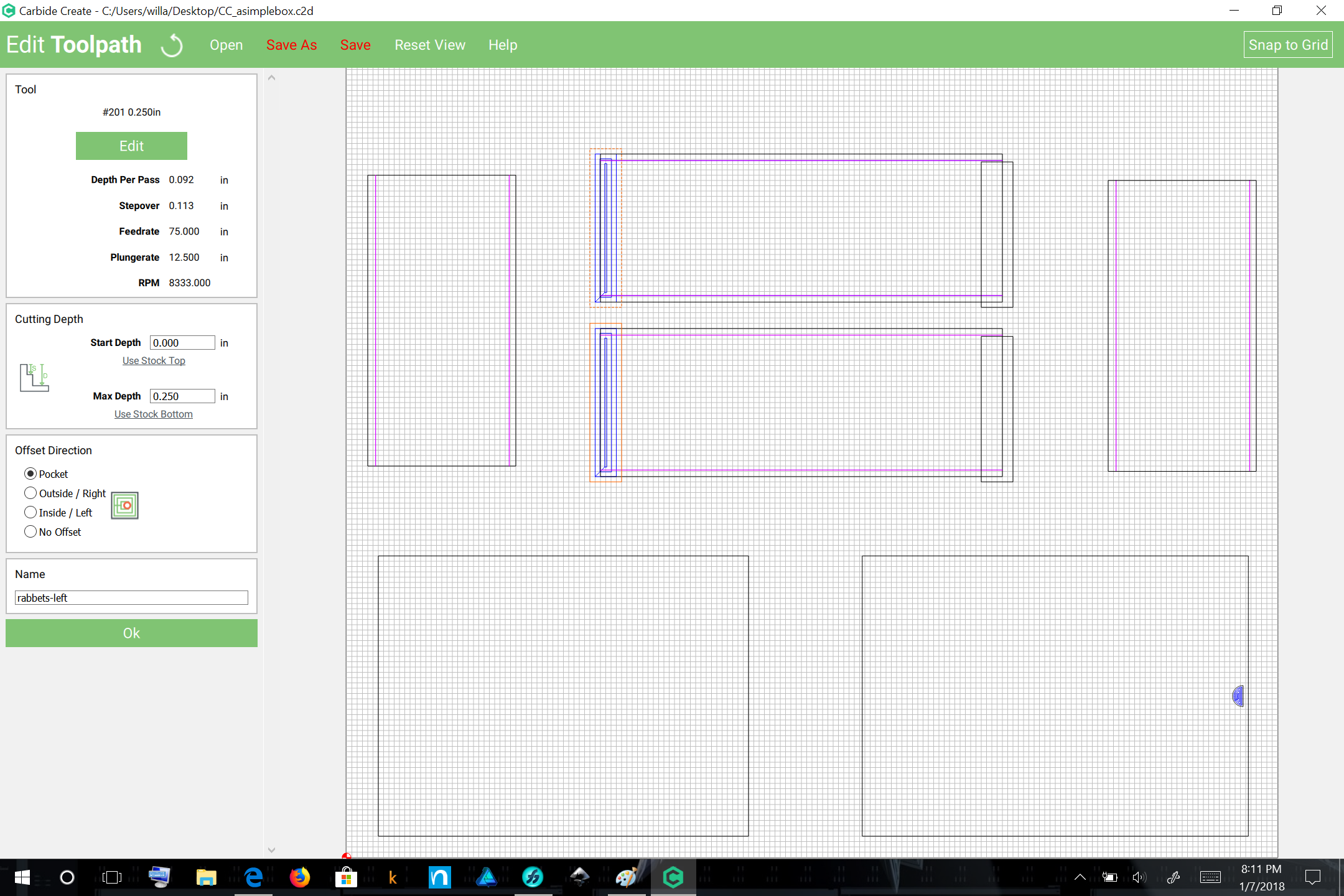
Next begin drawing in the rabbets for the left side — these should be 3.5″ tall and 0.5″ wide, but will need to be appropriately larger to ensure that the entire surface is cut — add at least the diameter of the endmill which you are using to the height and width, so:
@WillAdams Great write-up! It is really helpful to see the process, step-by-step. I would love to see more like this. Taking us “noobs” through the process, so we can learn is extremely helpful. Finished files are great, but the way you have done it helps immensely.
“Give a man a fish and feed him for a day. Teach a man to fish and feed him for a lifetime.”
We do things such as this on the support queue when asked — seems to help some folks get started on their own projects.
I’m hoping that once I’ve gotten this one written up I can re-work it as a parametric file — ideally it’ll be a set:
parameter file
OpenSCAD file to create a 3D preview
METAPOST file to create an SVG which can be imported into Carbide Create — I did pick up a couple of books on Python and I’ve been hoping I can work up a success to @chaunax’s rabbeted box generator since it’s gone off-line
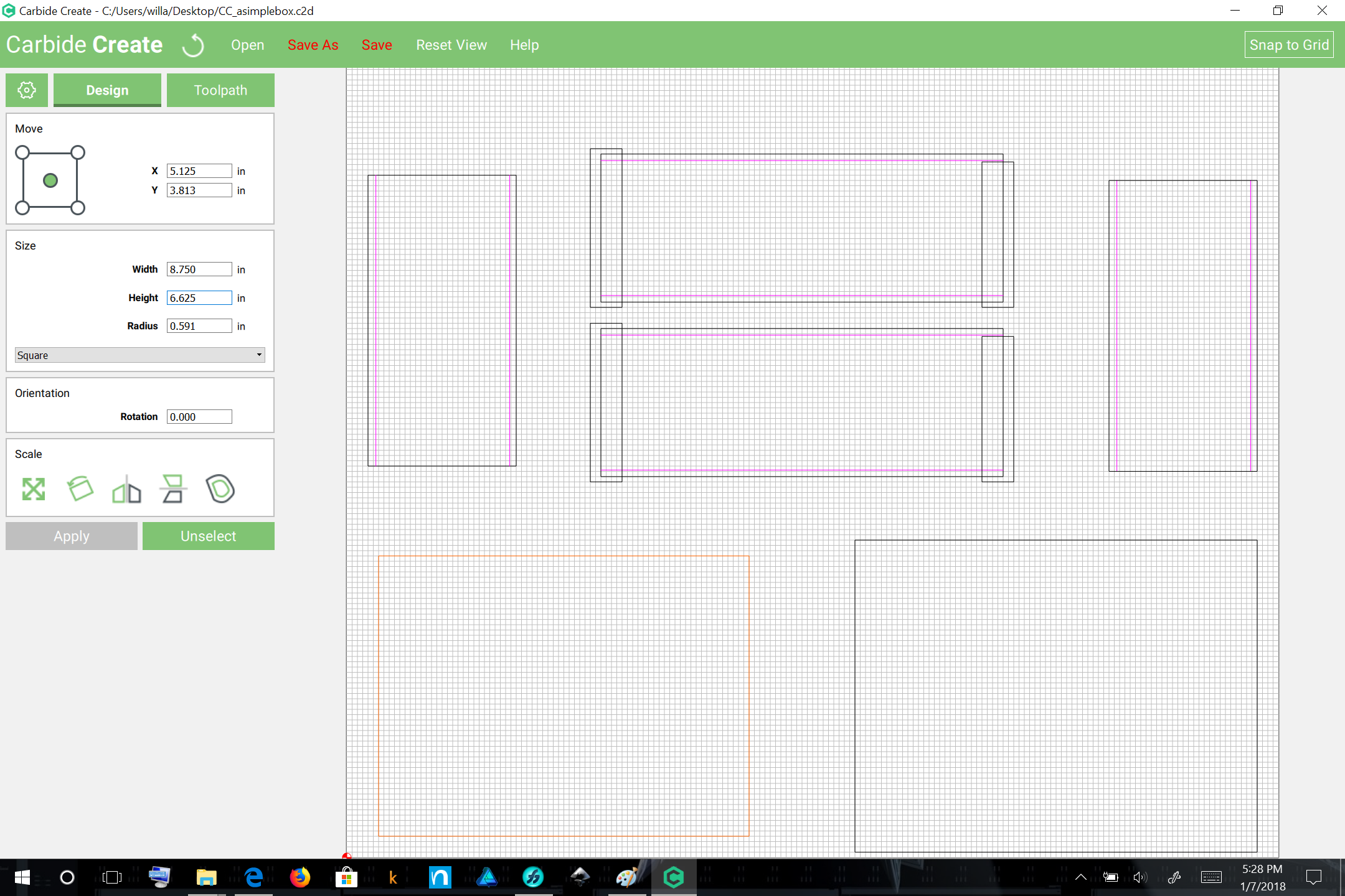
The next step is to determine how deep those pockets will be, leaving what thickness, which determines in turn, how much the sides will need to be shortened. Half seems about right, so the sides should be shortened by the material thickness:
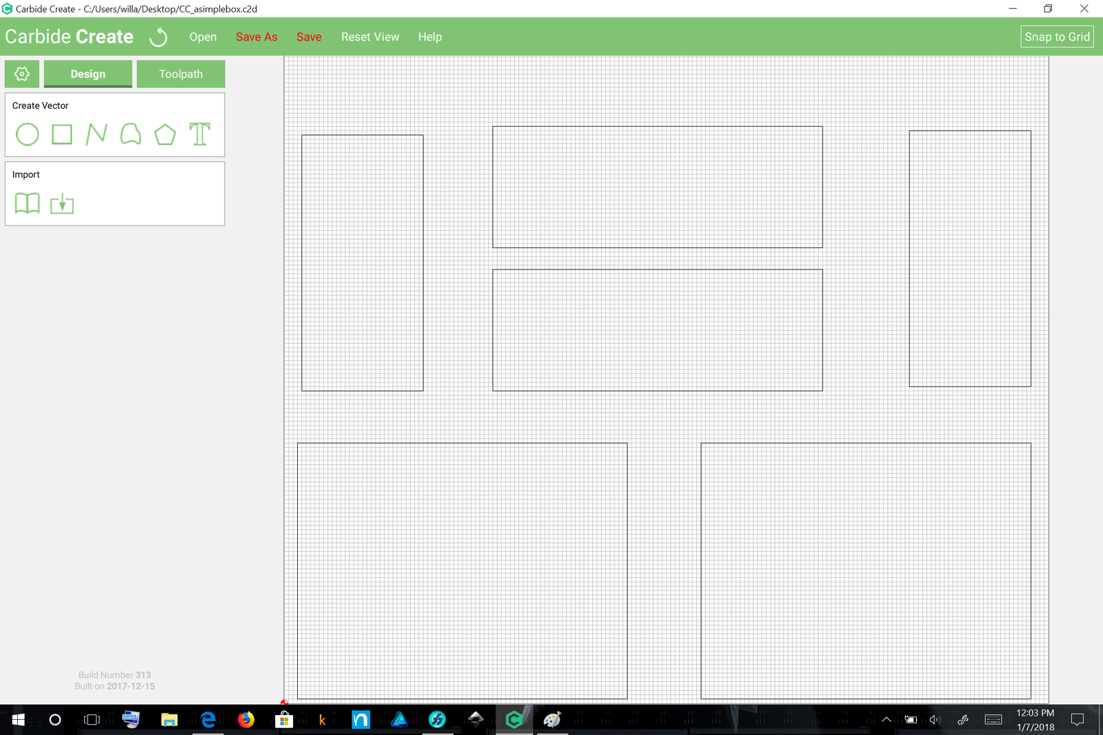
At this point, it may be helpful to review the appearance from overhead:
The visible portion of the bottom (from the underside of the box) will be 8.5″ × 6.375″ — the dadoes may be any depth up to the 0.25″ of the rabbet — the material thickness of 1/16″ is a bit shallow, so we double it to keep the math simple. A worthwhile improvement is to cut this dado with a ball-nosed endmill — this will result in a rounded bottom which will be stronger and less likely to break. It also makes adjust the fit by sanding the inset part easier.
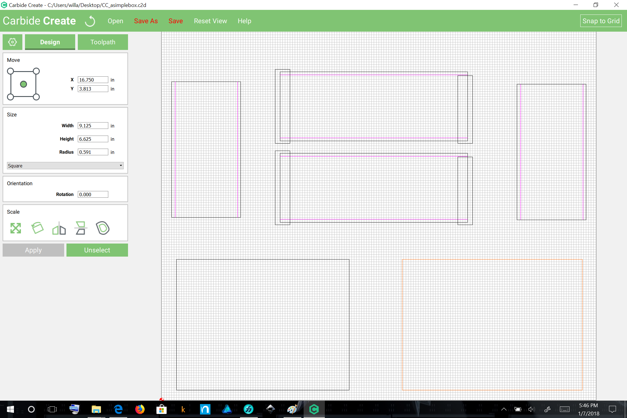
The dimensions of the back should be a bit less than that, adjusted as desired for using a ball-nosed endmill — simpler to use the 0.25″ for the part dimension and to increase the 1/8″ depth slightly.
If we were using thicker materials for the front and back we would add geometry to cut rabbets to allow them to fit. Instead, they’ll simply slide into place.
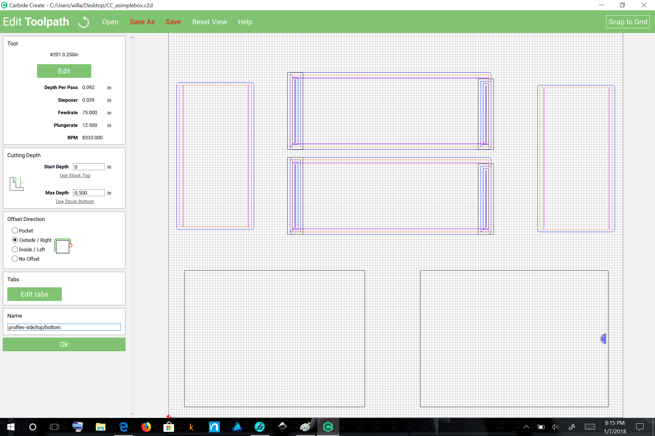
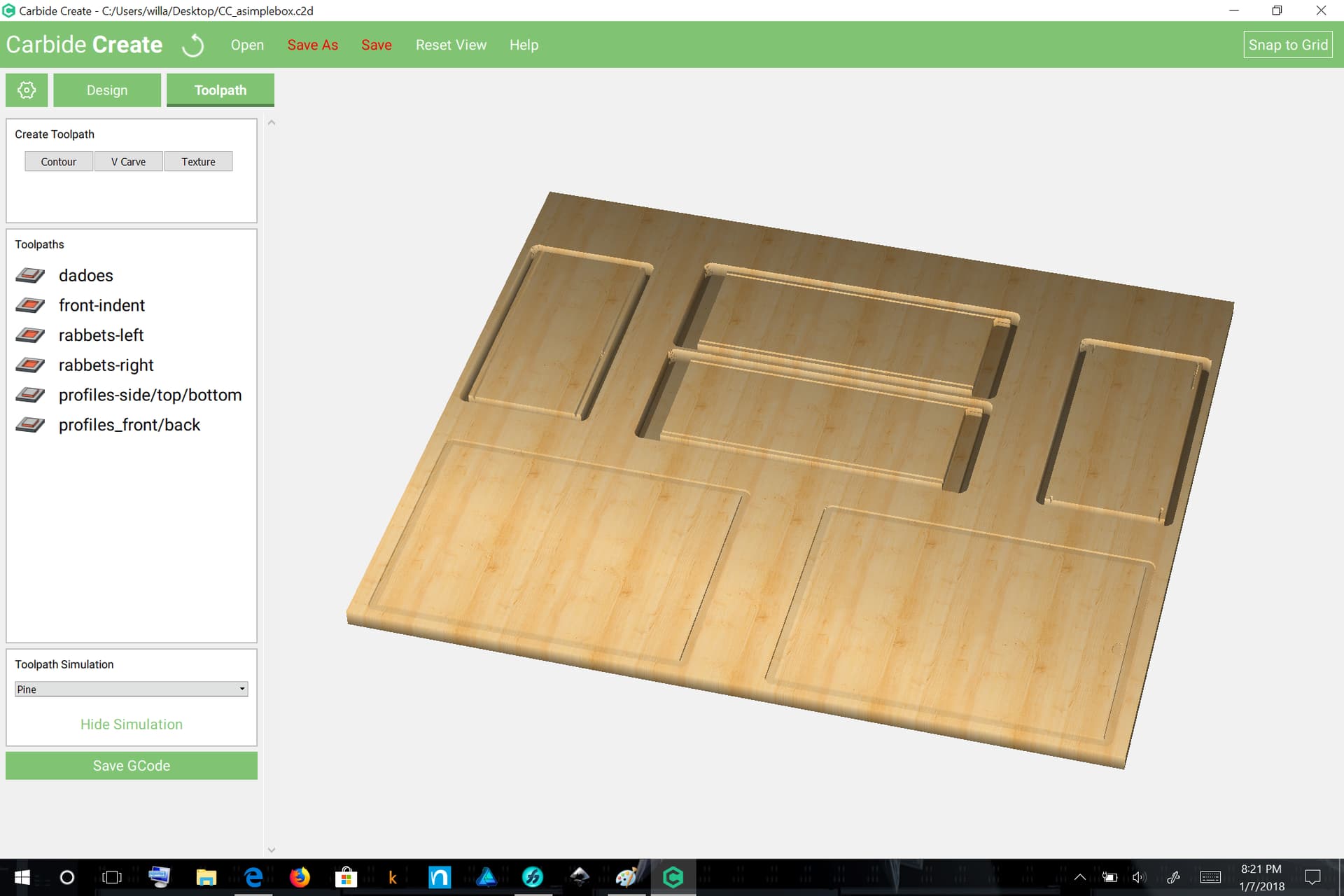
And at this point we’re essentially done. All that’s left to do is assign toolpaths. Here we will assume that folks will cut one part at a time — the way I do that is to assign all the toolpaths, save the file, duplicate the file once for each part w/ an appropriate name, then open each and delete everything which is not needed, then export G-Code.